EP4162289B1 - Système lidar à commande grossière d'angle - Google Patents
Système lidar à commande grossière d'angle Download PDFInfo
- Publication number
- EP4162289B1 EP4162289B1 EP21730862.6A EP21730862A EP4162289B1 EP 4162289 B1 EP4162289 B1 EP 4162289B1 EP 21730862 A EP21730862 A EP 21730862A EP 4162289 B1 EP4162289 B1 EP 4162289B1
- Authority
- EP
- European Patent Office
- Prior art keywords
- light
- view
- lidar system
- angle control
- field
- Prior art date
- Legal status (The legal status is an assumption and is not a legal conclusion. Google has not performed a legal analysis and makes no representation as to the accuracy of the status listed.)
- Active
Links
Images


Classifications
-
- G—PHYSICS
- G01—MEASURING; TESTING
- G01S—RADIO DIRECTION-FINDING; RADIO NAVIGATION; DETERMINING DISTANCE OR VELOCITY BY USE OF RADIO WAVES; LOCATING OR PRESENCE-DETECTING BY USE OF THE REFLECTION OR RERADIATION OF RADIO WAVES; ANALOGOUS ARRANGEMENTS USING OTHER WAVES
- G01S7/00—Details of systems according to groups G01S13/00, G01S15/00, G01S17/00
- G01S7/48—Details of systems according to groups G01S13/00, G01S15/00, G01S17/00 of systems according to group G01S17/00
- G01S7/481—Constructional features, e.g. arrangements of optical elements
- G01S7/4817—Constructional features, e.g. arrangements of optical elements relating to scanning
-
- G—PHYSICS
- G01—MEASURING; TESTING
- G01S—RADIO DIRECTION-FINDING; RADIO NAVIGATION; DETERMINING DISTANCE OR VELOCITY BY USE OF RADIO WAVES; LOCATING OR PRESENCE-DETECTING BY USE OF THE REFLECTION OR RERADIATION OF RADIO WAVES; ANALOGOUS ARRANGEMENTS USING OTHER WAVES
- G01S7/00—Details of systems according to groups G01S13/00, G01S15/00, G01S17/00
- G01S7/48—Details of systems according to groups G01S13/00, G01S15/00, G01S17/00 of systems according to group G01S17/00
- G01S7/481—Constructional features, e.g. arrangements of optical elements
- G01S7/4814—Constructional features, e.g. arrangements of optical elements of transmitters alone
- G01S7/4815—Constructional features, e.g. arrangements of optical elements of transmitters alone using multiple transmitters
-
- G—PHYSICS
- G01—MEASURING; TESTING
- G01S—RADIO DIRECTION-FINDING; RADIO NAVIGATION; DETERMINING DISTANCE OR VELOCITY BY USE OF RADIO WAVES; LOCATING OR PRESENCE-DETECTING BY USE OF THE REFLECTION OR RERADIATION OF RADIO WAVES; ANALOGOUS ARRANGEMENTS USING OTHER WAVES
- G01S7/00—Details of systems according to groups G01S13/00, G01S15/00, G01S17/00
- G01S7/48—Details of systems according to groups G01S13/00, G01S15/00, G01S17/00 of systems according to group G01S17/00
- G01S7/483—Details of pulse systems
- G01S7/486—Receivers
- G01S7/4861—Circuits for detection, sampling, integration or read-out
- G01S7/4863—Detector arrays, e.g. charge-transfer gates
-
- G—PHYSICS
- G01—MEASURING; TESTING
- G01S—RADIO DIRECTION-FINDING; RADIO NAVIGATION; DETERMINING DISTANCE OR VELOCITY BY USE OF RADIO WAVES; LOCATING OR PRESENCE-DETECTING BY USE OF THE REFLECTION OR RERADIATION OF RADIO WAVES; ANALOGOUS ARRANGEMENTS USING OTHER WAVES
- G01S7/00—Details of systems according to groups G01S13/00, G01S15/00, G01S17/00
- G01S7/48—Details of systems according to groups G01S13/00, G01S15/00, G01S17/00 of systems according to group G01S17/00
- G01S7/483—Details of pulse systems
- G01S7/486—Receivers
- G01S7/4865—Time delay measurement, e.g. time-of-flight measurement, time of arrival measurement or determining the exact position of a peak
-
- G—PHYSICS
- G02—OPTICS
- G02F—OPTICAL DEVICES OR ARRANGEMENTS FOR THE CONTROL OF LIGHT BY MODIFICATION OF THE OPTICAL PROPERTIES OF THE MEDIA OF THE ELEMENTS INVOLVED THEREIN; NON-LINEAR OPTICS; FREQUENCY-CHANGING OF LIGHT; OPTICAL LOGIC ELEMENTS; OPTICAL ANALOGUE/DIGITAL CONVERTERS
- G02F1/00—Devices or arrangements for the control of the intensity, colour, phase, polarisation or direction of light arriving from an independent light source, e.g. switching, gating or modulating; Non-linear optics
- G02F1/01—Devices or arrangements for the control of the intensity, colour, phase, polarisation or direction of light arriving from an independent light source, e.g. switching, gating or modulating; Non-linear optics for the control of the intensity, phase, polarisation or colour
- G02F1/13—Devices or arrangements for the control of the intensity, colour, phase, polarisation or direction of light arriving from an independent light source, e.g. switching, gating or modulating; Non-linear optics for the control of the intensity, phase, polarisation or colour based on liquid crystals, e.g. single liquid crystal display cells
- G02F1/133—Constructional arrangements; Operation of liquid crystal cells; Circuit arrangements
- G02F1/1333—Constructional arrangements; Manufacturing methods
- G02F1/1335—Structural association of cells with optical devices, e.g. polarisers or reflectors
- G02F1/133528—Polarisers
- G02F1/133541—Circular polarisers
-
- G—PHYSICS
- G02—OPTICS
- G02F—OPTICAL DEVICES OR ARRANGEMENTS FOR THE CONTROL OF LIGHT BY MODIFICATION OF THE OPTICAL PROPERTIES OF THE MEDIA OF THE ELEMENTS INVOLVED THEREIN; NON-LINEAR OPTICS; FREQUENCY-CHANGING OF LIGHT; OPTICAL LOGIC ELEMENTS; OPTICAL ANALOGUE/DIGITAL CONVERTERS
- G02F1/00—Devices or arrangements for the control of the intensity, colour, phase, polarisation or direction of light arriving from an independent light source, e.g. switching, gating or modulating; Non-linear optics
- G02F1/01—Devices or arrangements for the control of the intensity, colour, phase, polarisation or direction of light arriving from an independent light source, e.g. switching, gating or modulating; Non-linear optics for the control of the intensity, phase, polarisation or colour
- G02F1/13—Devices or arrangements for the control of the intensity, colour, phase, polarisation or direction of light arriving from an independent light source, e.g. switching, gating or modulating; Non-linear optics for the control of the intensity, phase, polarisation or colour based on liquid crystals, e.g. single liquid crystal display cells
- G02F1/133—Constructional arrangements; Operation of liquid crystal cells; Circuit arrangements
- G02F1/1333—Constructional arrangements; Manufacturing methods
- G02F1/1337—Surface-induced orientation of the liquid crystal molecules, e.g. by alignment layers
- G02F1/133769—Surface-induced orientation of the liquid crystal molecules, e.g. by alignment layers comprising an active, e.g. switchable, alignment layer
-
- G—PHYSICS
- G01—MEASURING; TESTING
- G01S—RADIO DIRECTION-FINDING; RADIO NAVIGATION; DETERMINING DISTANCE OR VELOCITY BY USE OF RADIO WAVES; LOCATING OR PRESENCE-DETECTING BY USE OF THE REFLECTION OR RERADIATION OF RADIO WAVES; ANALOGOUS ARRANGEMENTS USING OTHER WAVES
- G01S17/00—Systems using the reflection or reradiation of electromagnetic waves other than radio waves, e.g. lidar systems
- G01S17/88—Lidar systems specially adapted for specific applications
- G01S17/89—Lidar systems specially adapted for specific applications for mapping or imaging
- G01S17/894—Three-dimensional [3D] imaging with simultaneous measurement of time-of-flight at a two-dimensional [2D] array of receiver pixels, e.g. time-of-flight cameras or flash lidar
-
- G—PHYSICS
- G01—MEASURING; TESTING
- G01S—RADIO DIRECTION-FINDING; RADIO NAVIGATION; DETERMINING DISTANCE OR VELOCITY BY USE OF RADIO WAVES; LOCATING OR PRESENCE-DETECTING BY USE OF THE REFLECTION OR RERADIATION OF RADIO WAVES; ANALOGOUS ARRANGEMENTS USING OTHER WAVES
- G01S17/00—Systems using the reflection or reradiation of electromagnetic waves other than radio waves, e.g. lidar systems
- G01S17/88—Lidar systems specially adapted for specific applications
- G01S17/93—Lidar systems specially adapted for specific applications for anti-collision purposes
- G01S17/931—Lidar systems specially adapted for specific applications for anti-collision purposes of land vehicles
Definitions
- Various embodiments relate to a LIDAR system (i.e. a "Light Detection And Ranging" system).
- a LIDAR system is a sensing system that illuminates a scene to provide information about the scene, such as the objects within it (e.g., their size, their speed, their direction of movement, and the like).
- An example LIDAR architecture includes a fine-angle control element (e.g., an optical phased array, OPA) and a (separate) coarse-angle control element (e.g., a liquid crystal polarization grating, LCPG) for controlling a direction of light emitted onto the scene (in other words, for beamsteering the light emitted into a field of view of the LIDAR system).
- OPA optical phased array
- LCPG liquid crystal polarization grating
- the field of view is divided into a plurality of sections (also called "tiles") to which light can be directed (and from which light can be received).
- the LIDAR system can be designed for fields of view from +/-100 to +/-600 and the LCPG can have 4 to 16 horizontal tiles through which the measuring system is switched, i.e. the tiles in the field of view are approached one after the other via the LCPG within a LIDAR frame.
- the LIDAR system can, for example, have 1 to 16 laser diodes as the light source, which can also be individually switchable.
- the required resolution in the horizontal direction for a typical LIDAR measurement is approximately 0.05° to 1°. In most cases, it is therefore not sufficient to achieve the horizontal resolution within an LCPG tile using the laser diode channels; one or more lasers illuminate each column, thus achieving the horizontal resolution. Therefore, the fine angle control element is also used for the horizontal resolution. This means that the horizontal resolution within one of the LCPG tiles is achieved using the fine angle control element (e.g., with a one-dimensional MEMS mirror). The fine angle control element is clearly used to achieve the fine beam deflection in the horizontal direction.
- the LIDAR system thus has a component for realizing fine beam deflection, which increases the complexity of the system, e.g. with regard to the required optics and the required synchronization of the operation of the component with the operation of the light source.
- the LIDAR system comprises a transmitter unit, a detection unit, and a controller.
- the transmitter unit emits at least one light beam to perform a measurement
- the detection unit detects a component reflected during the measurement. Components in the transmitter unit and the detection unit are movable.
- the distance measuring unit for signal-time-based distance measurement of the distance to an object located in a detection field.
- the distance measuring unit comprises a transmitter unit with a plurality of transmitters for transmitting pulses and a receiver unit for receiving echo pulses.
- the distance measuring unit is configured to assign the echo pulses to the various solid angle segments.
- EP 3627175 A1 discloses an optoelectronic sensor comprising a light receiver, a receiving optics system upstream of the light receiver, and a control and evaluation unit.
- the receiving optics system has a beam deflection device with several switchable blaze gratings of different grating constants arranged one behind the other.
- the control and evaluation unit is configured to switch a blaze grating on and off depending on a desired deflection angle of the beam deflection device with the same grating constants but different blaze angles.
- a LIDAR system includes a first quarter-wave plate, a first deflection stage, and a detector.
- the first quarter-wave plate generates a circularly polarized scanning light beam.
- the first deflection stage selects a rotation direction for a polarization vector of the scanning beam and deflects the scanning beam by a selected angle based on the selected rotation direction of the polarization vector.
- the detector receives a reflected beam, which is a reflection of the scanning beam from the object.
- the LCPG can be used with flash illumination and a two-dimensional detector array of a time-of-flight (ToF) camera.
- ToF time-of-flight
- the entire field of view (also referred to as field of view) of the camera is illuminated at once, resulting in reduced intensity and thus reduced range.
- Various embodiments relate to a LIDAR system in which a portion of the spatial resolution (e.g., resolution in a first direction) is provided by the emitter side (also referred to as the transmit side) and another portion of the spatial resolution (e.g., resolution in a second direction) is provided by the receiver side.
- the scan directions of the emitter and receive sides of the LIDAR system are reversed, such that the transmit side is used for resolution in one direction (e.g., the vertical direction) and the receive side is used for another direction (e.g., the horizontal direction).
- a LIDAR system can be provided in which a portion of the spatial resolution of a LIDAR measurement (e.g., spatial resolution in a first direction) is provided by the spatial arrangement of a plurality of partial light sources (e.g., individual laser diodes) of the LIDAR system, and another portion of the spatial resolution of the LIDAR measurement (e.g., spatial resolution in a second direction) is provided by the spatial arrangement of a plurality of detector pixels of a detector of the LIDAR system.
- Various embodiments relate to a LIDAR system in which the (two-dimensional) spatial resolution of the LIDAR measurement is provided by the relative arrangement of a plurality of partial light sources to detector pixels.
- first direction and the second direction may be represented as the horizontal direction and the vertical direction (or vice versa). However, it should be understood that the first direction and the second direction may be any two directions at an angle to each other, allowing the sub-light sources to emit light toward the LIDAR system's field of view and allowing the detector pixels to receive light outside the LIDAR system's field of view.
- first direction and the second direction may be any two directions along which spatial resolution is to be achieved.
- a LIDAR system may include a coarse angle control element for controlling a beam direction of the emitted light and/or the received light.
- the coarse angle control element may be configured to control (e.g., change) the propagation direction of both the light emitted by the LIDAR system into the field of view and the light received by the LIDAR system from the field of view.
- a coarse angle control element can be understood as a device which is configured (e.g., controllable) to control a propagation direction of the light propagating through (in other words, passing through) the coarse angle control element.
- the coarse angle control element can be configured to provide a deflection angle (also referred to as a deflection angle) for deflecting the light propagating through the coarse angle control element (e.g., to provide a controllable output angle).
- the deflection angle can be defined by controlling one or more properties of the coarse angle control element, such as, for example, with respect to Fig. 2A to Fig. 2F described.
- the coarse angle control element may enable coarse control of the deflection angle, such that the deflection angle cannot be varied continuously, but can assume one of a plurality of discrete values.
- the coarse angle control element may be configured (e.g., controlled) to assume one of a plurality of possible operating states, wherein the operating state defines a corresponding deflection angle for the light.
- the number of possible operating states may depend on the properties of the coarse angle control element (e.g., the number of switchable liquid crystal layers, by way of example only), as will be explained in more detail below.
- the coarse angle control element may be or comprise a liquid crystal polarization grating. However, it is to be understood that a liquid crystal polarization grating is only one example of a possible coarse angle control element, and other types of devices may also be used (e.g., a mirror).
- the field of view can be considered to be composed of a plurality of "tiles" (illustratively, a plurality of discrete sections). Each tile can be associated with a corresponding deflection angle.
- the term "tile” e.g., field of view tile or LCPG tile
- a tile can further describe a (discrete) section of the field of view from which light can be received (e.g., detected).
- the detector can be used for resolution in the first direction within a tile.
- the individual light sources or groups of light sources e.g., laser diodes or groups of laser diodes
- the detector can be used for resolution in the horizontal direction and the light emitters for resolution in the vertical direction if the field of view of a tile has fewer rows than columns.
- a receiver diode array e.g., an avalanche photodiode array, APD
- APD avalanche photodiode array
- the relative spatial arrangement of the detector pixels and the partial light sources, in combination with the angular deflection capabilities of the coarse angle control element, can eliminate the need for a fine angle deflection element, e.g., an OPA or even a MEMS mirror (as examples only).
- the spatial resolution within a tile can be achieved in various embodiments by a crossed arrangement of a light source (e.g., a laser bar) and a detector (e.g., a 1D detector array).
- Sequential use of the partial light sources e.g., laser diodes of a laser bar, such as an 8-laser bar or 16-laser bar
- the partial light sources of a light source can be fired (visually activated) one after the other to provide the spatial resolution.
- This can have the advantage of eliminating a complex component (OPA, MEMS, or similar). This also eliminates the need for control of this component (usually implemented with an FPGA or ASIC), and simplifies the optics.
- the problem of the light from the partial light sources (e.g., from the lasers) having to pass through the fine-angle deflection element also no longer exists.
- the optics consist of fewer lenses, which reduces losses and reduces assembly effort. By omitting the fine-angle deflection element, the cost and complexity of the LIDAR system are significantly reduced. Furthermore, without the fine-angle deflection element, a truly "solid-state" LIDAR is achieved, which operates entirely without moving parts, which can also increase reliability.
- LIDAR system that can enable two-dimensional spatial resolution without using a fine-angle control element (e.g., without using a MEMS mirror).
- the LIDAR system can be described in various embodiments as a LCPG and a non-MEMS LIDAR system, for example, as a flash LIDAR with LCPG.
- a LIDAR system according to claim 1 is provided.
- the dependent claims show preferred embodiments.
- the second direction may be perpendicular to the first direction.
- the first direction may be the horizontal direction and the second direction the vertical direction.
- the first direction may be the vertical direction and the second direction the horizontal direction.
- first direction and the second direction may be perpendicular to an optical axis of the LIDAR system.
- the coarse angle control element may be configured to deflect light at a deflection angle relative to the optical axis of the LIDAR system.
- the deflection angle may be an angle of a plurality of discrete deflection angles (e.g. assigned to a respective operating state of the coarse angle control element).
- the coarse angle control element can be configured to deflect light from the light source at a first deflection angle to illuminate a portion of the field of view.
- the coarse angle control element can be configured to control a deflection angle (and an exit angle) of the light emitted into the field of view so that the light is emitted into a portion of the field of view.
- the coarse angle control element can be configured (e.g., controlled) to provide different deflection angles sequentially so that different portions of the field of view are illuminated sequentially.
- the coarse angle control element may be configured to deflect light from the field of view at a second deflection angle to deflect light from a portion of the field of view onto the detector.
- An illuminated portion of the field of view may have a first angular extent in a first field of view direction of approximately 2° to approximately 20° and a second angular extent in a second field of view direction perpendicular to the first field of view direction of approximately 2° to approximately 20°.
- the angular extent of a section of the field of view may depend on the properties of the coarse angle control.
- the number of sections into which the field of view can be divided may depend on the properties of the coarse angle control.
- first field of view direction and the second field of view direction may be perpendicular to the optical axis of the LIDAR system.
- first field of view direction may be the horizontal direction and the second field of view direction may be the vertical direction.
- Each section (e.g., each tile) of the field of view may be or become subdivided into a plurality of subsections, e.g., into a first plurality of (first) subsections in the first direction and into a second plurality of (second) subsections in the second direction.
- a subsection can be assigned to a respective detector pixel. For example, each subsection along the direction in which the detector pixels are arranged can be assigned to a respective detector pixel. Illustratively, each detector pixel can detect light from the assigned subsection.
- the resolution in the first direction can depend on the number of subsections (in various aspects, on the number of detector pixels) in the first direction (e.g., be proportional).
- a subsection can be assigned to a respective partial light source.
- each subsection along the direction in which the partial light sources are arranged can be assigned to a be assigned to the respective partial light source.
- each partial light source can emit light into the associated subsection.
- the resolution in the second direction can depend on the number of subsections (in various aspects, on the number of partial light sources) in the second direction (e.g., be proportional).
- a first deflection angle element (also referred to as a deflection angle part or deflection angle component) can be provided in a first field of view direction (e.g., in the horizontal or vertical direction) and a second deflection angle element can be provided in a second field of view direction perpendicular to the first field of view direction.
- the coarse angle control element can be configured to deflect the light in one direction and/or in two directions (e.g., the LIDAR system can be a 1D scanning system or a 2D scanning system).
- the first output angle element may have a value in a range of approximately -60° to approximately +60° with respect to the optical axis of the LIDAR system.
- the second output angle element may have a value in a range of approximately -15° to approximately +15° with respect to the optical axis of the LIDAR system.
- the plurality of partial light sources may include a first partial light source and a second partial light source.
- the light emission controller may be configured to control the first partial light source and the second partial light source such that the first partial light source emits light in a first emission time period and the second partial light source emits light in a second emission time period.
- a waiting time between the first emission time period and the second emission time period is greater than or substantially equal to a maximum propagation time of the emitted light.
- the second emission time period may follow the first emission time period (and then further emission time periods, e.g. from further partial light sources).
- the waiting time allows the light emitted by the first partial light source to return to the LIDAR system (and be detected by the detector) before the second partial light source emits light. This can reduce or significantly eliminate overlap between the light emissions of different partial light sources, thus improving the quality of the measurement.
- the LIDAR system may further include an angle control controller configured to control one or more light redirection properties of the coarse angle control element to define a deflection angle of the deflected light.
- the angle control controller may be configured to control the coarse angle control element to provide a first deflection angle of the deflected light in a first angle control time period and to provide a second deflection angle of the deflected light in a second angle control time period.
- the second angle control time period following the second angle control time period.
- the angle control controller may be configured to control the light deflection properties of the coarse angle control element such that different deflection angles can be provided successively.
- the light emission controller may be configured to control the partial light sources of the plurality of partial light sources such that each partial light source emits light in the respective emission time period within the first angle control time period, and that each partial light source emits light in the respective emission time period within the second angle control time period.
- the light emission controller may be configured to control the partial light sources of the plurality of partial light sources such that a portion of the field of view (e.g., associated with the first deflection angle) is completely illuminated (in other words, that each partial portion is illuminated by the associated partial light source).
- the coarse angle control element may comprise at least one liquid crystal element.
- the coarse angle control element may be or comprise a liquid crystal polarization grating.
- a grating period of the liquid crystal polarization grating may define the deflection angle.
- the coarse angle control element may include a liquid crystal layer and a polarization grating.
- the liquid crystal layer may be configured to define a polarization of the light propagating through the liquid crystal layer.
- the polarization grating may be configured to define the deflection angle of the light based on its polarization.
- the coarse angle control element may be or include a liquid crystal polarization grating.
- the angle control controller may be configured to provide a control signal (e.g., a voltage, such as a modulated voltage, e.g., a DC voltage that is switched on and off) to the liquid crystal polarization grating to control an alignment of the liquid crystal molecules.
- a control signal e.g., a voltage, such as a modulated voltage, e.g., a DC voltage that is switched on and off
- the alignment of the liquid crystal molecules defines a grating period of the liquid crystal polarization grating.
- the angle control controller may be configured to provide a first control signal to the liquid crystal polarization grating in a first angular time period to define a first grating period of the liquid crystal polarization grating.
- the angle control controller may be configured to provide a second control signal to the liquid crystal polarization grating in a second angular time period (e.g., after the first angular time period) to define a second grating period of the liquid crystal polarization grating.
- the angle control controller may control the grating period of the liquid crystal polarization grating to provide different deflection angles.
- the coarse angle control element may comprise a liquid crystal layer and a polarization grating.
- the angle control controller may be configured to provide a control signal to the liquid crystal layer to control an alignment of the liquid crystal molecules of the liquid crystal layer.
- the alignment of the liquid crystal molecules defines (e.g., changes) the polarization of the light propagating through the liquid crystal layer.
- the angle control controller may be configured to provide a first control signal to the liquid crystal layer in a first angular time period to define a first polarization of the light propagating through the liquid crystal layer.
- the angle control controller may be configured to provide a second control signal to the liquid crystal layer in a second angular time period to define a second polarization of the light propagating through the liquid crystal layer.
- the polarization grating may thus provide a first deflection angle for the light in the first angular time period based on the first polarization and provide a second deflection angle for the light in the second angular time period based on the second polarization.
- the light source may comprise at least one laser light source.
- the partial light sources may comprise at least one laser light source (e.g., each partial light source may be or comprise a laser light source).
- the at least one laser light source may comprise a laser diode.
- the at least one laser diode may be an edge-emitting laser diode or a component-side light-emitting diode (Vertical Cavity Surface Emitting Laser, VCSEL).
- the light source may comprise a laser bar.
- the partial light sources may be laser diodes of the laser bar.
- a fast axis of the laser bar may be aligned along the direction in which the partial light sources are arranged (e.g., along the second direction).
- the detector may have at least one photodiode.
- the photodiode may be configured to generate an electrical signal (e.g., a voltage or a current) when light strikes the at least one photodiode.
- each detector pixel may have a photodiode or be assigned (e.g., connected) to a respective photodiode. It is understood that each detector pixel may also have a plurality of photodiodes or be assigned to a plurality of photodiodes (e.g., in the manner of a silicon photomultiplier).
- the at least one photodiode may be an avalanche photodiode, e.g., a single-photon avalanche photodiode.
- the detector may be or have a multi-pixel single-photon avalanche photodiode.
- the LIDAR system may further include a receiver optics assembly.
- the receiver optics assembly may be configured to receive light from the field of view and direct the received light toward the detector.
- the receiver optics assembly may be configured to Field of view (e.g., a portion of the field of view) onto the detector.
- the receiver optics arrangement can be configured to image a respective subsection of the field of view onto the associated detector pixel.
- the receiver optics arrangement can be arranged between the detector and the coarse angle control element.
- the receiver optics arrangement may include one or more lenses (e.g., one or more focusing lenses).
- the one or more lenses may be configured to focus the received light onto the detector (e.g., onto the respective detector pixels).
- the LIDAR system may further comprise a transmission optics assembly.
- the transmission optics assembly may be configured to receive light from the light source (e.g., from the partial light sources) and direct the received light onto the coarse angle control element.
- the transmission optics assembly may be arranged between the light source and the coarse angle control element.
- the transmission optics assembly may comprise a first collimator lens.
- the first collimator lens may be configured to collimate the light emitted by the light source onto the coarse angle control element.
- the first collimator lens may be configured to collimate light in a first (optical) direction.
- the first collimator lens may collimate the light in the direction of the slow axis of the light source, for example, in a direction perpendicular to the direction in which the partial light sources are arranged.
- the first collimator lens may be a "slow-axis collimator" (SAC).
- the emission optics arrangement may include a second collimator lens.
- the second collimator lens may be arranged between the light source and the first collimator lens.
- the second collimator lens may be configured to collimate the light emitted by the light source onto the first collimator lens.
- the second collimator lens may be configured to collimate light in a second (optical) direction.
- the second collimator lens may collimate the light in the direction of the fast axis of the light source, for example, in the direction in which the sub-light sources are arranged.
- the second collimator lens may be a "fast-axis collimator" (FAC).
- FAC fast-axis collimator
- the emission optics arrangement may further comprise a multi-lens array for mixing the light emitted by each of the plurality of partial light sources.
- the multi-lens array may be arranged between the light source and the coarse angle control element (e.g., between the first collimator lens and the coarse angle control element).
- the multi-lens array may have a zone structure along the second direction (illustratively, along the direction in which the partial light sources are arranged). The zone structure enables the light emitted by one partial light source to be well separated from the light emitted by another partial light source.
- the LIDAR system may be or will be configured as a flash LIDAR system.
- a vehicle may have one or more LIDAR systems as described herein.
- Fig. 1A and Fig. 1B 1 and 2 each show a schematic representation of a top view of a LIDAR system 100 according to various embodiments.
- the LIDAR system 100 may be or become installed (e.g., integrated) in a vehicle (e.g., in a car equipped with automated driving functions, for example).
- the LIDAR system 100 may include an emitter side for emitting light into a field of view 102 and a receiver side for receiving (e.g., detecting) light from the field of view 102.
- the LIDAR system 100 may further include an angle control stage for controlling (e.g., changing) the direction of propagation of the light from the emitter side to the field of view 102 and/or from the field of view 102 to the receiver side.
- the field of view 102 can be the field of view of the LIDAR system 100.
- the field of view 102 can correspond to the emission field of the emitter side (e.g., the emission field of a light source or a plurality of partial light sources) and/or the field of view of the receiver side (e.g., the field of view of a detector).
- the field of view of a detector of the LIDAR system 100 can essentially correspond to the emission field of a light source (e.g., a plurality of partial light sources) of the LIDAR system 100.
- the LIDAR system 100 may include a detector 104 (e.g., on the receiver side, for example, as part of a light detection system).
- the detector 104 may be configured to detect light from the field of view 102.
- the detector 104 may be configured to provide a signal (e.g., an electrical signal, such as a voltage or a current) when light impinges on the detector 104 (e.g., on one or more detector pixels), as will be explained in more detail below (e.g., with respect to Fig. 4A to Fig. 4E ).
- the signal may be provided from detector 104 to one or more processors of LIDAR system 100 (e.g., an analog signal from detector 104 may be converted to a digital signal using an analog-to-digital converter and provided to the processors).
- the one or more processors may, for example, be configured to analyze the signal(s) from detector 104 to reconstruct the scene in field of view 102.
- the detector 104 may include a plurality of detector pixels 106.
- the detector pixels 106 of the plurality of detector pixels 106 may be arranged along a first direction (e.g., along the horizontal direction as in Fig. 1A shown or along the vertical direction as in Fig. 1B shown). In various embodiments, the detector pixels 106 may form an array along the first direction.
- At least one detector pixel 106 e.g., each detector pixel 106) may be configured to generate a signal (e.g., a current, such as a photocurrent) when light is incident on the detector pixel 106 (e.g., the signal may be proportional to the amount of incident light), as will be explained in more detail below.
- Each detector pixel 106 of the plurality of detector pixels 106 may be associated with a respective subsection of the field of view 102.
- each detector pixel 106 may be associated with detecting light from a corresponding subsection of the field of view 106.
- each detector pixel 106 may receive light from the associated subsection of the field of view 102 to detect light therefrom.
- the receiver side (and/or the angle control stage) of the LIDAR system 100 may be configured to map each subsection of the field of view 102 onto the associated detector pixel 106.
- the LIDAR system 100 may include a light source 110.
- the light source 110 may include a plurality of partial light sources 112 (also referred to as light radiators, light emitters, or emitter pixels).
- the light source 110 may include a plurality of individual light sources 112 that are individually addressable (e.g., controllable), as will be explained in more detail below, e.g., with respect to the Fig. 3A to Fig. 3G .
- the partial light sources 112 (generally, the light source 110) may be configured to emit light into the field of view 102.
- the partial light sources 112 of the plurality of partial light sources 112 can be arranged along a second direction. In various aspects, the partial light sources 112 can form an array in the second direction.
- the second direction may be at an angle to the first direction.
- the angle between the first direction and the second direction may not be 0° or 180°; in other words, the first direction may not be parallel to the second direction (illustratively, the second direction may not be the same direction as the first direction).
- the first direction and the second direction may be any two directions that form an angle with each other and enable the emission and reception of light.
- the first direction may be any direction that forms an angle with an optical axis 108 of the LIDAR system 100 and allows the detector 104 to receive light from the field of view 102.
- the second direction may be any direction that forms an angle with the optical axis 108 of the LIDAR system 100 and allows the light source 110 (e.g., the sub-light sources 112) to emit light in the direction of the field of view 102.
- the first direction and the second direction may be perpendicular to the optical axis 108 of the LIDAR system 100 in various aspects (e.g., the optical axis 108 may be along the direction 152 in Fig. 1A and Fig. 1B aligned).
- the first direction and the second direction may be perpendicular to each other in various embodiments.
- the first direction may be the horizontal direction, e.g., direction 154 in Fig. 1A and Fig. 1B
- the second direction is the vertical direction, e.g. direction 156 in Fig. 1A and Fig. 1B
- the detector pixels 106 can be arranged in a row and the light sources 112 in a column (see Fig. 1A ).
- the first direction may be the vertical direction and the second direction may be the horizontal direction. In this case, the detector pixels 106 may be arranged in a column and the light sources 112 may be arranged in a row (see Fig. 1B ).
- Each sub-light source 112 may be associated with a respective sub-portion of the field of view 102 (or a respective plurality of sub-portions).
- the sub-light sources 112 may be configured (e.g., arranged) such that each sub-light source 112 illuminates a respective sub-portion of the field of view 102 (e.g., a sub-portion of a tile, as explained in more detail below).
- the emitter side (and/or the angle control stage) of the LIDAR system 100 may be configured such that each sub-portion of the field of view 102 is illuminated by the associated sub-light source 112.
- the relative spatial arrangement (e.g., the crossed arrangement) of the detector pixels 106 to the partial light sources 112 may enable the detector pixels 106 to be used to provide spatial resolution in the first direction and the partial light sources 112 to be used to provide spatial resolution in the second direction.
- the LIDAR system 100 may include a light emission controller 118 (e.g., one or more processors).
- the light emission controller 118 may be configured to control the light emission of the light source 110.
- the light emission controller 118 may control the sub-light sources 112 of the plurality of sub-light sources 112 such that each sub-light source 112 emits light in a respective emission time period.
- the light emission controller 118 can assign an emission time period to each partial light source 112, such that a single partial light source 112 emits light during each emission time period.
- the light emission controller 118 can be configured to control the partial light sources 112 such that each partial light source 112 emits light during the associated emission time period and not during the emission time period associated with another partial light source 112. This can enable there to be substantially no (e.g., temporal and/or spatial) overlap in the light emission of the partial light sources 112. This allows any desired (e.g., predefined) spatial resolution to be achieved in the direction along which the partial light sources 112 are arranged.
- the light emission controller 118 may be configured to control the partial light sources 112 such that they emit light in accordance (e.g., in synchronization) with a control of a coarse angle control element 114, as will be explained in more detail below.
- the LIDAR system 100 may include (e.g., at the angle control stage) a coarse angle control element 114.
- the coarse angle control element 114 may be configured to deflect light, e.g., both light, which is emitted by the light source 110 into the field of view 102, as well as light coming from the field of view 102 towards the detector 104 (e.g. towards the receiver side).
- the coarse angle control element 114 can be configured to deflect light from the light source 110 (e.g. from the partial light sources 112) towards the field of view 102 (e.g. at a first deflection angle) and to deflect light from the field of view 102 towards the detector 104 (e.g. at a second deflection angle).
- the coarse angle control element 114 can be configured to deflect the light at multiple deflection angles (e.g. discrete deflection angles), for example, with respect to the Fig. 2A to Fig. 2F described.
- the coarse angle control element 114 can be configured to deflect light from the partial light sources 112 into the field of view 102 at a (e.g., discrete) deflection angle such that a portion of the field of view 102 is illuminated.
- the coarse angle control element 114 can be configured to control a deflection angle (and an exit angle) of the light emitted into the field of view 102 such that the light is emitted into a portion of the field of view 102.
- the coarse angle control element 114 can be configured (e.g., controlled) to provide different deflection angles one after the other so that different portions of the field of view 102 are illuminated one after the other, as will be explained in more detail below.
- the field of view 102 can be understood as having a plurality of sections (tiles), each associated with a corresponding deflection angle.
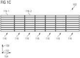
- An exemplary subdivision of the field of view 102 into a plurality of sections 116 is shown in Fig. 1C shown, according to various embodiments.
- the field of view 102 may include a first plurality of sections along the first direction and a second plurality of sections along the second direction (e.g., may be divided into the first plurality and the second plurality of sections).
- the field of view 102 may be described as a matrix of tiles 116 arranged along the horizontal direction and the vertical direction (e.g., the field of view 102 may be divided into a plurality of rows and columns, each associated with a plurality of tiles 116).
- the subdivision of the field of view 102 e.g., the arrangement of the tiles 116) may have any shape and configuration, e.g., depending on the relative arrangement of the first direction with respect to the second direction.
- the number of tiles 116 into which the field of view 102 is divided may depend on the configuration of the LIDAR system 100, e.g., on the configuration of the coarse angle control element 114.
- the angular extent of the field of view 102 in the first direction and in the second direction may depend on the configuration of the LIDAR system 100. Only as a numerical For example, the field of view 102 may have an angular extent with a value in a range of 100° to 130° in the horizontal direction (e.g., 120°, i.e., +/-60° with respect to the optical axis 108).
- the field of view 102 may have an angular extent with a value in a range of 10° to 60° in the vertical direction (e.g., 20°, i.e., +/-10° with respect to the optical axis 108, or 24°).
- the field of view 102 may include seven tiles arranged in the horizontal direction and eight tiles arranged in the vertical direction. As another numerical example, the field of view 102 may include eight tiles in the horizontal direction and four tiles in the vertical direction. As another numerical example, the field of view 102 may include eight tiles in the horizontal direction and six tiles in the vertical direction.
- the size, e.g., the angular extent, of a tile 116 may depend on the properties of the coarse angle control 114 (e.g., the angles achievable with the coarse angle control 114).
- the tiles 116 may all have the same size (e.g., the same angular extent in the first direction and in the second direction). In various aspects, at least one tile 116 may have a different size with respect to another tile 116. For example, a tile 116 at an edge of the field of view 102 may have a larger size than a tile 116 in the center of the field of view 102 (e.g., a larger angular extent, e.g., in the horizontal direction, as in Fig. 1C for a first tile 116-1 having a larger size than a second tile 116-2).
- a tile 116 may have a first angular extent in a first field of view direction (e.g., in the first direction) with a value in a range of approximately 2° to approximately 20°.
- a tile 116 may have an angular extent in the horizontal direction of approximately 4°, for example, approximately 7.5°, for example, approximately 15°.
- a tile 116 may have a second angular extent in a second field of view direction (e.g., perpendicular to the first field of view direction, such as in the second direction) with a value in a range of about 2° to about 20°.
- a tile 116 may have an angular extent in the vertical direction of about 2.5°, for example, about 4°, for example, about 6°, for example, about 15°.
- Each tile 116 of the field of view 102 may be or become divided into a plurality of subsections, e.g., into a first plurality of (first) subsections in the first direction and into a second plurality of (second) subsections in the second direction.
- the spatial resolution of the LIDAR system 100 in a direction may depend on the angular extent of a tile 116 along that direction and on the number of detector pixels 112 or partial light sources 116 arranged along that direction.
- the resolution of the LIDAR system 100 in a direction may be calculated by dividing the angular extent of a tile 116 along that direction by the number of partial light sources 112 or detector pixels 106 arranged along that direction.
- the number of partial light sources 112 or detector pixels 106 arranged along a direction may correspond to the number of subsections into which a tile 116 can be divided in that direction.
- a resolution in this direction can be achieved in a case where a tile 116 has an angular extent in the horizontal direction of 15° and 64 detector pixels 106 are arranged in this direction.
- a resolution in this direction of approximately 0.23° can be achieved in a case where a tile 116 has an angular extent in the vertical direction of 2.5° and 8 partial light sources 112 are arranged in this direction.
- the detector 104 has 64 detector pixels 106 arranged in the horizontal direction, and the light source 110 has 16 partial light sources 112 arranged in the vertical direction, a horizontal resolution of approximately 0.12° and a vertical resolution of approximately 0.25° can be achieved.
- a horizontal resolution of approximately 0.25° and a vertical resolution of approximately 0.19° can be achieved.
- the coarse angle control element 114 may be configured to deflect the light from the field of view 102 at a second deflection angle to the detector 104.
- the coarse angle control element 114 may be configured to receive light from the field of view 102 and deflect the received light to the receiver side of the LIDAR system 100 (e.g., to a receiver optics assembly, such as with respect to the Fig. 4E described).
- the first deflection angle may have the same value as the second deflection angle (e.g., with respect to the optical axis 108, e.g., in the horizontal direction and/or in the vertical direction). In various aspects, the first deflection angle may have a different value compared to the second deflection angle, e.g., depending on the direction of the incident light and/or a state of the coarse angle control element 114.
- Fig. 2A and Fig. 2B each show a schematic representation of a coarse angle control element 200 (e.g. the coarse angle control element 114, which in Fig. 1A and Fig. 1B shown).
- a coarse angle control element 200 e.g. the coarse angle control element 114, which in Fig. 1A and Fig. 1B shown.
- the coarse angle control element 200 may be configured to deflect light in multiple directions, as indicated by the arrows in Fig. 2A and Fig. 2B is shown, e.g., to deflect light with multiple deflection angles.
- the deflected light can be deflected towards a field of view 202 (e.g., a field of view of a LIDAR system, e.g., into the field of view 102 of the LIDAR system 100) (see Fig. 2A ), for example, to illuminate a portion of the field of view 202.
- the deflected light may be light received from the field of view 202, e.g., to deflect it onto a detector of a LIDAR system (e.g., onto the detector 104 of the LIDAR system 100), see Fig. 2B
- the coarse angle control element 200 may be configured to deflect light at a deflection angle independent of the direction in which the light propagates.
- the deflection angle may be an angle relative to an optical axis of the coarse angle control element 200 (e.g., relative to an optical axis of a LIDAR system, e.g., the optical axis 108 of the LIDAR system 100).
- the deflection angle can be selected from a plurality of (discrete) deflection angles.
- the coarse angle control element 200 can be configured (e.g., controlled) to provide one deflection angle from a set of possible deflection angles.
- each deflection angle can be associated with a respective operating state of the coarse angle control element 200.
- An angular resolution of the coarse angle control element 200 (e.g., a minimum difference between possible deflection angles) can depend on the properties of the coarse angle control element 200.
- the coarse angle control element 200 can have an angular resolution (e.g., in the horizontal and/or vertical direction) of 10°, for example, of 5°, for example, greater than 1°, or greater than 3°.
- the coarse angle control element 200 can have an angular resolution in a range from approximately 1° to approximately 15°.
- the coarse angle control element 200 may have an angular resolution of 7.5° in the horizontal direction and 6° in the vertical direction.
- the coarse angle control element 200 can be configured to deflect light in one direction and/or in two directions.
- the deflection angle can include a first deflection angle element in a first field of view direction (e.g., in the horizontal or vertical direction) and a second deflection angle element in a second field of view direction at an angle to the first field of view direction (e.g., perpendicular to the first field of view direction).
- first field of view direction and the second field of view direction can be perpendicular to the optical axis of the coarse angle control element 200.
- the range of a value of a deflection angle element in a direction may define the angular extent of the field of view 202 in that direction.
- the first output angle element may have a value in a range of approximately -60° to approximately +60° with respect to the optical axis of the coarse angle control element 200.
- the second output angle element may have a value in a range of approximately -15° to approximately +15° with respect to the optical axis of the coarse angle control element 200.
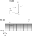
- An angle control controller 204 may be configured to control the coarse angle control element 200, as shown in Fig. 2C and Fig. 2E
- the angle control controller 204 may be part of a LIDAR system, e.g., the LIDAR system 100.
- the angle control controller 204 may be configured to control one or more light deflection properties of the coarse angle control element 200 to define a deflection angle of the deflected light.
- the angle control controller 204 may be configured to place the coarse angle control element 200 into an operating state to provide the associated deflection angle.
- the angle control controller 204 may be configured to provide (e.g., supply) a control signal (e.g., a control voltage) to the coarse angle control element 200 to place the coarse angle control element 200 in an operating state (e.g., associated with the control signal).
- a control signal e.g., a control voltage
- the angle control controller 204 may be configured to provide one of a plurality of control signals to the coarse angle control element 200 to place the coarse angle control element 200 in one of a plurality of operating states.
- the angle control controller 204 may be configured to provide a first control signal S1 to the coarse angle control element 200 to define a first deflection angle (e.g., to illuminate a first tile 202-1 of the field of view 202), as shown in Fig. 2C and Fig. 2D
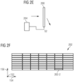
- the angle control controller 204 may be configured to provide a second control signal S2 to the coarse angle control element 200 to define a second deflection angle (e.g., to illuminate a second tile 202-2 of the field of view 202), as shown in Fig. 2E and Fig. 2F is shown.
- the angle control controller 204 is shown providing a control signal to the coarse angle control element 200 to illuminate various portions of the field of view 202. It should be understood that a similar operation may be performed in the case of light received from the field of view 202 (and deflected, for example, onto a detector).
- the angle control controller 204 may be configured to control the coarse angle control element to provide a deflection angle in a respective time period (also referred to as an angle control time period).
- the angle control controller 204 may be configured to control the coarse angle control element to provide a plurality of deflection angles in a plurality of respective angle control time periods (e.g., one after the other), e.g., to sequentially illuminate different tiles of the field of view 102.
- the angle control controller 204 may be configured to control the coarse angle control element 200 to provide a first deflection angle of the deflected light in a first angle control time period (e.g., to illuminate a first tile 202-1 of the field of view 202). see for example the Fig. 2D .
- the angle control controller 204 may be configured to control the coarse angle control element 200 to provide a second deflection angle of the deflected light in a second angle control time period (e.g., to illuminate a second tile 202-2 of the field of view 202), see, for example, the Fig. 2F .
- the second angle control time period may follow the second angle control time period (and may be followed by further angle control time periods with further deflection angles).
- the angle control controller 204 may control the coarse angle control element such that the tiles are illuminated sequentially.
- the order in which the tiles are illuminated may correspond to any desired illumination pattern.
- the tiles may be illuminated sequentially along a same column or a same row.
- the elements may be illuminated in a manner that reduces (e.g., minimizes) the number of slow transitions in the liquid crystals.
- the operation of the angle control controller 204 may be in accordance with the light emission, e.g., with the operation of a light emission controller (e.g., the light emission controller 118 of the LIDAR system 100), as explained in more detail below.
- the angle control controller 204 may be configured to change the operating state of the coarse angle control element 200 (and the deflection angle) after the tile of the field of view associated with the current operating state has been fully illuminated (e.g., by each sub-light source 112 of the LIDAR system 100). In other words, only after all sub-light sources (e.g., laser diodes) have successively illuminated an entire tile at least once does the coarse angle control element (e.g., the LCPG) advance to the next tile.
- sub-light sources e.g., laser diodes
- the coarse angle control element 200 may comprise at least one (e.g., switchable) liquid crystal element.
- the liquid crystal element may comprise a layer of liquid crystal molecules arranged between two electrodes (e.g., two ITO electrodes), e.g., on a glass substrate.
- the coarse angle control element 200 may include a plurality of liquid crystal elements. Each liquid crystal element may define a respective partial deflection angle, as explained in more detail below.
- the deflection angle of the coarse angle control element 200 may be defined by a combination (e.g., a sum) of the plurality of partial deflection angles.
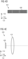
- the coarse angle control element 200 may comprise a quarter-wave plate arranged upstream of the (first) liquid crystal element to convert linearly polarized light into circularly polarized light.
- the coarse angle control element 200 may be or comprise a liquid crystal polarization grating (e.g., a switchable nematic Liquid crystal polarization grating, for example comprising a photopolymerizable polymer.
- a grating period of the liquid crystal polarization grating can define the deflection angle.
- the liquid crystal can be periodically poled and have a lattice structure defined by the alignment of the liquid crystal molecules.
- the alignment of the liquid crystal molecules can define (e.g., control or change) the deflection angle of the light propagating through the liquid crystal polarization grating.
- the liquid crystal polarization grating can be configured to deflect or transmit light in three possible directions (in different aspects, with three possible deflection angles), depending on the grating period and the polarization of the incident light.
- a first operating state if no voltage (e.g., control voltage) is applied to the liquid crystal polarization grating, the incident light is deflected in a first direction or in a second direction depending on its polarization (e.g., depending on the polarization state, for example, right- or left-circular).
- the light is deflected at a first deflection angle or at a second deflection angle (e.g., opposite to the first deflection angle with respect to an optical axis of the grating).
- the polarization of the output light is also reversed to the opposite orthogonal polarization (e.g., from right-circular to left-circular or vice versa).
- the grating period in some aspects, the grating profile
- the incident light can pass through essentially unchanged (e.g., at a third deflection angle with a value of essentially 0°).
- the angle control controller 204 may be configured to control the liquid crystal polarization grating.
- the angle control controller 204 may be configured to provide a control signal (e.g., a voltage, for example, other than a DC voltage) to the liquid crystal polarization grating to control the alignment of the liquid crystal molecules (e.g., one or more grating properties of the liquid crystal polarization grating).
- a control signal e.g., a voltage, for example, other than a DC voltage
- the angle control controller 204 may be configured to provide a first control signal (e.g., a first control voltage) to the liquid crystal polarization grating in a first angular time control period to define a first grating period of the liquid crystal polarization grating (e.g., the presence of a grating period).
- the angle control controller 204 may be configured to provide a second control signal (e.g., a second control voltage) to the liquid crystal polarization grating in a second angular time control period to define a second grating period of the liquid crystal polarization grating (e.g., the absence of a grating period).
- the first control voltage may have a value of 0 V so that the respective grating property can provide a (first or second) deflection angle depending on the polarization of the light.
- the second control voltage may have a value greater than the value of the first control voltage to cancel the grating period, allowing light to travel through the grating unchanged.
- the angle control controller 204 can control the grating period of the liquid crystal polarization grating to provide different deflection angles.
- the liquid crystal polarizing grating may comprise a plurality of liquid crystal polarizing gratings.
- Each liquid crystal polarizing grating may be configured to deflect light in three respective directions.
- Each liquid crystal polarizing grating may both add and subtract the deflection angle, thereby providing a wider angular range. The number of possible deflection angles may thus depend on the number of liquid crystal polarizing gratings.
- the control voltage may comprise a plurality of control voltages supplied to the plurality of liquid crystal polarizing gratings to individually control their grating properties.
- the coarse angle control element 200 may comprise a liquid crystal layer and a polarization grating.
- the liquid crystal layer may be configured to define a polarization of the light propagating through the liquid crystal layer.
- the alignment of the liquid crystal molecules defines (e.g., changes) the polarization of the light propagating through the liquid crystal layer.
- the liquid crystal layer may be configured as a switchable polarization selector, e.g., as a switchable half-wave plate.
- the liquid crystal layer may have a first state in which it does not change the polarization of the light and a second state in which it reverses the polarization of the light (e.g., from right-circular to left-circular or vice versa).
- the polarization grating may be configured to define the deflection angle of the light based on its polarization.
- the angle control controller 204 may be configured to provide a first control signal (e.g., a first control voltage, e.g., 0 V) to the liquid crystal layer in a first angle control time period to define a first polarization of the light propagating through the liquid crystal layer (in other words, to bring the liquid crystal layer into the first state).
- the angle control controller 204 may be configured to provide a second control signal (e.g., a second control voltage, e.g., greater than the first control voltage) to the liquid crystal layer in a second angle control time period to define a second polarization of the light propagating through the liquid crystal layer (in other words, to bring the liquid crystal layer into the second state).
- the polarization grating can thus provide a first deflection angle for the light in the first angle control time period based on the first polarization and provide a second deflection angle for the light in the second angle control time period based on the second polarization.
- the coarse angle control element 200 may comprise a plurality of liquid crystal layers and/or a plurality of polarization gratings (e.g., stacked or laminated, one after the other) to increase the range of possible deflection angles (in a similar manner as described for the liquid crystal polarization grating above).
- the number and horizontal and vertical angular extent (also referred to as the angular range) of the tiles can be selected by the design of the liquid crystal element.
- the number of tiles can be proportional to the number of liquid crystal layers, e.g., the number of controllable (switchable) layers.
- a liquid crystal element can be configured to provide more than 20 tiles, e.g., more than 30 tiles, e.g., more than 50 tiles.
- the maximum number of tiles can be limited by the switching time of the liquid crystal element (e.g., the liquid crystal polarization grating switching times).
- Fig. 3A to Fig. 3C each show a light source 300 in a schematic representation, according to various embodiments.
- the light source 300 may be a light source for a LIDAR system, e.g., the light source 110 of the LIDAR system 100.
- the light source 300 may include a plurality of partial light sources 302 (e.g., the partial light sources 112 of the LIDAR system 100).
- the partial light sources 302 of the plurality of partial light sources 302 may be arranged in one direction (e.g., adjacent to one another).
- the partial light sources 302 can be arranged in the vertical direction (see Fig. 3A ) or arranged in the horizontal direction (see Fig. 3B ). In various aspects, the partial light sources 302 may be arranged in a direction that forms an angle other than 90° with an optical axis of the light source 300 (e.g., with an optical axis of a LIDAR system). As exemplified in Fig. 3C As shown, the partial light sources 302 can be arranged in a direction 45° to the optical axis.
- the plurality of partial light sources 302 may comprise any number of partial light sources 302, for example, 8 partial light sources, 16 partial light sources, or 32 partial light sources.
- the number of partial light sources 302 may determine a resolution in the direction in which the partial light sources 302 are arranged. For example, in a case where eight partial light sources 302 are arranged in the vertical direction, a portion 304 of a field of view (such as in Fig. 3D shown), into which the partial light sources 302 emit light, have eight partial sections 306. Each partial section 306 can be illuminated by a respective light source 302.
- each partial light source 302 can illuminate a partial section 306 that has an angular extent of 15° in the horizontal direction and 0.31° in the vertical direction.
- each partial light source 302 can completely illuminate a section 304 into which Direction perpendicular to the direction in which the partial light sources 302 are arranged.
- Each partial light source 302 can illuminate a partial section 306 in the direction in which the partial light sources 302 are arranged.
- a subsection 306 can be understood as a pixel illuminated by a respective partial light source 302. If the field of view is divided into 8 tiles in the vertical direction and each tile is divided into 8 subsections 306, 64 pixels can be specified, only as a numerical example.
- the light source 300 (e.g., at least one partial light source 302, e.g., each partial light source 302) may be configured to emit light in the visible and/or infrared wavelength range.
- the light source 300 may be configured to emit light in the wavelength range from approximately 700 nm to approximately 2000 nm, for example, at 905 nm or at 1550 nm.
- the light source 300 may include at least one laser light source.
- the partial light sources 302 may include at least one laser light source (e.g., each partial light source may be or include a laser light source).
- the at least one laser light source may comprise a laser diode.
- the at least one laser diode may be an edge-emitting laser diode or a component-side light-emitting diode.
- the light source 300 can comprise a laser bar.
- the partial light sources 302 can be laser diodes of the laser bar.
- a fast axis of the laser bar can be aligned along the direction in which the partial light sources 302 are arranged.
- the laser bar can have an active area having a size of 0.1 mm in the horizontal direction and 0.48 mm in the vertical direction.
- the light source 300 may be part of a light emission system 310, as shown in Fig. 3E, Fig. 3F , Fig. 3G and Fig. 3H is shown (e.g., the light emission system 310 may be a light emission system of the LIDAR system 100).
- the light emission system 310 may include a light emission controller 312 to control the light source 300 (e.g., the plurality of sub-light sources 302).
- the light emission controller 312 may be an example of the light emission controller 118 of the LIDAR system 100.
- the light emission controller 312 may be configured to control the plurality of partial light sources 302 such that the partial light sources 302 emit light sequentially (e.g., each in a respective emission time period).
- the mode of operation may be such that only a single partial light source 302 (e.g., a single laser diode) pulses and generates a stripe (e.g., a partial section, for example, in the horizontal direction). The spatial resolution within this strip is then taken over by a detector (e.g. a detector row), as in relation to Fig. 4A to Fig. 4E will be explained in more detail.
- the light emission controller 312 may be configured to control a first sub-light source and a second sub-light source such that the first sub-light source emits light in a first emission time period (e.g., associated with the first sub-light source) and the second sub-light source emits light in a second emission time period (e.g., associated with the second sub-light source).
- the second emission time period may follow the first emission time period (e.g., immediately after the first emission time period, with no further emission time periods in between).
- the light emission controller 312 may be configured to wait a waiting time after a sub-light source 302 has emitted light before controlling the next sub-light source 302 to emit light (e.g., after the first sub-light source has emitted light before controlling the second sub-light source to emit light).
- the waiting time between consecutive emission time periods (e.g., between the first emission time period and the second emission time period) may be equal to or greater than a maximum propagation time of the emitted light (e.g., a maximum propagation time of a LIDAR system incorporating the light emission system, such as the LIDAR system 100).
- the maximum delay time can be calculated as 2*d max /c, where d max is the maximum range of the LIDAR system (in various aspects, a maximum distance from the system at which an object can be located and still be detected) and c is the speed of light.
- a delay time can be greater than 100 ns, for example, greater than 1 ⁇ s, for example, greater than 2 ⁇ s (corresponding to a maximum range of approximately 300 m). This can result in a detector of the LIDAR system (e.g., detector 104 of LIDAR system 100) being unable to distinguish which pulse is being received.
- the light emission controller 312 may be configured to control the partial light sources 302 in accordance with an angle control controller of a LIDAR system (e.g., the angle control controller 204).
- an angle control controller of a LIDAR system e.g., the angle control controller 204.
- the light emission controller 312 may be configured to control the partial light sources 302 such that each partial light source 302 emits light for each deflection angle provided by a coarse angle control element (e.g., coarse angle control element 118) of the LIDAR system.
- each partial light source 302 may be controlled to emit light in an angle control time period defined by the angle control controller.
- the light emission controller 312 may be configured to control the partial light sources 302 such that each partial light source 302 emits light in the respective emission time period within a first Angle control time period, and that each partial light source 302 emits light in the respective emission time period within a second angle control time period.
- the light emission system 310 may include an optical arrangement (e.g., an emission optics arrangement 314) as shown in Fig. 3F to Fig. 3H is shown.
- the transmit optics assembly 314 may be disposed downstream of the light source 300, e.g., between the light source 300 and the field of view.
- the transmit optics assembly 314 may be disposed between the light source 300 and a coarse angle control element (e.g., the coarse angle control element 118) to direct (e.g., focus or collimate) light from the light source 300 to the coarse angle control element.
- the transmit optics assembly 314 may include one or more lenses, e.g., one or more collimator lenses (also referred to as collimating lenses).
- the emitting optics assembly 314 may include a first collimator lens 316 (e.g., a first cylindrical lens) to collimate the light emitted by the light source 300 to a field of view (e.g., to a coarse angle control element).
- the first collimator lens 316 may be a "slow-axis collimator lens" to collimate the emitted light toward the slow axis of the light source 300.
- the first collimator lens 316 may have a focal length of approximately 44 mm.
- the first collimator lens 316 can collimate the light such that the collimated light fills only a portion of a tile of the field of view in the direction in which the light is collimated by the first collimator lens 316.
- the first collimator lens 316 can reduce the beam expansion to the required (e.g., horizontal) angle (e.g., 7.5°).
- the emitting optics assembly 314 may include a second collimator lens 318 (e.g., a second cylindrical lens).
- the second collimator lens 318 may be disposed between the light source 300 and the first collimator lens 316 to collimate the light emitted by the light source 300 onto the first collimator lens 316.
- the second collimator lens 318 may be a "fast axis collimator lens" to collimate the emitted light toward the fast axis of the light source 300.
- the second collimator lens 318 may be configured for beam shaping.
- the second collimator lens 318 may have a focal length of approximately 38 ⁇ m.
- the focal length of the first collimator lens 316 and the second collimator lens 318 can be selected (e.g., adjusted) according to the size of the light source 300, e.g., the width of the active area of a laser bar.
- the emitting optics assembly 314 may comprise a multi-lens array 320, as shown in Fig. 3G (for partial light sources, such as four laser diodes arranged in the vertical direction) and in Fig. 3H (for partial light sources arranged in the horizontal direction).
- the multi-lens array can be configured to mix the light emitted by each partial light source of the plurality of partial light sources.
- the multi-lens array 320 can be arranged downstream of the first collimator lens 316, e.g., between the first collimator lens 316 and a coarse angle control element (e.g., the coarse angle control element 118).
- the multi-lens array 320 may have a zone structure (as shown in inset 322), e.g., a plurality of zones (e.g., a first zone 320-1 and a second zone 320-2).
- the multi-lens array 320 may cause a strong (in other words, sharp) separation of the light emitted by the partial light sources 302.
- the zone structure may be arranged in the direction in which the plurality of partial light sources 302 are arranged (e.g., in the vertical direction in Fig. 3G or horizontally in Fig. 3H ).
- the multi-lens array 320 can increase the virtual source size and thus provide increased eye safety, for example, when emitting light in the infrared range.
- the detector 400 may be a detector for a LIDAR system, e.g., the detector 104 of the LIDAR system 100.
- the detector 400 may be configured to detect light from a field of view (e.g., from the field of view of the LIDAR system).
- the detector 400 may have a plurality of detector pixels 402 (e.g., the detector pixels 106 of the LIDAR system 100).
- the detector pixels 402 of the plurality of detector pixels 402 may be arranged in one direction (e.g., side by side).
- the detector pixels 402 may be arranged in the horizontal direction (see Fig. 4A ) or arranged in the vertical direction (see Fig. 4B ).
- the detector pixels 402 may be arranged in a direction that forms an angle other than 90° with an optical axis of the detector 400 (e.g., with an optical axis of a LIDAR system).
- the detector pixels 402 may be arranged in a direction 45° to the optical axis.
- the plurality of detector pixels 402 may comprise any number of detector pixels 402, for example, 64 detector pixels or 128 detector pixels.
- the size of the detector 400 may correspond to the size of a tile 404 of the field of view (as in Fig. 4D shown) from which the detector 400 detects light.
- the detector 400 e.g., a 1x64 pixel APD array
- the detector 400 may have dimensions of 2.5 mm x 15 mm, corresponding to a tile 404 (also referred to as a cell) measuring 15° horizontally x 2.5° vertically.
- the detector 400 may have the same aspect ratio as a tile 404 (e.g., as an LCPG cell).
- the number of detector pixels 402 can determine a resolution in the direction in which the detector pixels 402 are arranged. As a numerical example, in a case where 64 detector pixels 402 are arranged in the horizontal direction (e.g., in a 64-pixel APD array), each detector pixel 402 1/64 of the 15° wide tile 404 horizontally and the entire 2.5° of the tile 404 vertically. Illustratively, each detector pixel 402 can detect light from a portion 406 of the tile 404. A horizontal resolution of approximately 0.23° can be achieved in this configuration. The resolution can be increased if 128 detector pixels 402 are used (e.g., in a 128-pixel APD array).
- the detector 400 may include a plurality of detectors (e.g., sub-detectors). For example, multiple detectors may be used to detect light from the field of view.
- the detectors may be arranged side by side, e.g., each detector may be associated with a respective column or row of the field of view (to detect light from the respective column or row).
- the detector 400 may include seven detectors, each detector having 64 detector pixels, so that 448 pixels may be used to detect light (in the horizontal or vertical direction).
- the detector 400 may include at least one photodiode.
- at least one (e.g., each) detector pixel 402 may include a photodiode or be coupled to a respective photodiode.
- the at least one photodiode may be an avalanche photodiode, e.g., a single-photon avalanche photodiode.
- the detector 400 may include or be an APD array or a SPAD array.
- the detector 400 may include or be a multi-pixel single-photon avalanche photodiode.
- a receiver optics assembly 408 may be used to image the field of view onto the detector 400, as shown in Fig. 4E is shown.
- the receiver optics can be designed such that the entire field of view is imaged onto the detector 400 (e.g., onto the APD line).
- the receiver optics arrangement 408 can be configured such that it images a respective subsection of the field of view onto a detector pixel 402 (e.g., assigned to the subsection).
- the receiver optics arrangement 408 can be arranged between the detector 400 and a coarse angle control element of a LIDAR system (e.g., the coarse angle control element 118).
- the receiver optics arrangement 408 can have one or more lenses (e.g., one or more focusing lenses).
- the receiver optics assembly 408 may include a lens 410 for focusing light onto the detector 400 (e.g., in the vertical and horizontal directions).
- the lens 410 may have the same focal length in the horizontal and vertical directions, for example, 57 mm.
- Fig. 5A, Fig. 5B and Fig. 5C each show a LIDAR system 500 in a schematic representation.
- the LIDAR system 500 may be an exemplary implementation of the LIDAR system 100.
- Only one optical element e.g. a multi-lens array
- other optical elements may also be present (e.g. a slow-axis collimator lens and/or a fast-axis collimator lens).
- the LIDAR system 500 may have a detector 502 on the receiver side.
- the detector may, for example, have 64 detector pixels (e.g., 64 channels) arranged in a horizontal direction, e.g., an array of 64 avalanche photodiodes.
- the LIDAR system 500 may further include receiver optics 504 on the receiver side, e.g., a lens (e.g., a focusing lens) for directing (e.g., focusing) light onto the detector 502.
- the LIDAR system 500 may have a laser module 506 on the emitter side, e.g., a laser bar with 8 laser diodes arranged in a vertical direction.
- the LIDAR system 500 may have emission optics for collimating the light emitted by the laser module 506.
- the LIDAR system 500 may include a first collimator lens 508 (e.g., a fast-axis collimator lens) and a second collimator lens 510 (e.g., a slow-axis collimator lens).
- the LIDAR system 500 may include a coarse angle control element 512, e.g., a liquid crystal polarizing grating, at the angle control stage.
- the liquid crystal polarizing grating may, as a numerical example only, have a horizontal dimension (e.g., a width) of approximately 50 mm and a vertical dimension (e.g., a height) of approximately 50 mm.
- the LIDAR system 500 may have a detector 514 on the receiver side, e.g., a 1D detector array with 32 or 64 detector pixels (e.g., 32 or 64 avalanche photodiodes) arranged in a horizontal direction.
- the LIDAR system 500 may further include receiver optics 516 on the receiver side for directing light onto the detector 514.
- the receiver optics 516 may be configured such that light from a tile 518 (e.g., an LCPG tile) is imaged onto the detector 514.
- the subsections of the tile 518 (which are arranged along the horizontal direction) are imaged by the receiver optics 516 onto the respective detector pixels.
- the striped subsection 518-1 may be imaged onto the striped detector pixel 514-1 (e.g., onto the APD cell).
- the tile 518 may, for example, have an angular extent of 7.5° in the horizontal direction and 4° in the vertical direction.
- the LIDAR system 500 may have a laser module 520 on the emitter side, e.g., a laser bar (e.g., a 1D emitter column) with 16 laser diodes arranged in the vertical direction (e.g., a 16-fold laser bar).
- the LIDAR system 500 may have a multi-lens array 522 to direct the light emitted by the laser module 520 into the field of view.
- the multi-lens array 522 may be configured such that light from each laser diode of the laser module 520 illuminates a respective subsection of the tile 518 (of the subsections arranged along the vertical direction) (e.g., subsection 518-2).
- the LIDAR system 500 in Fig. 5C The same component of the system can be Fig. 5B in a reversed configuration.
- the detector 514 may have detector pixels arranged in the vertical direction.
- the laser module 520 (and the multi-lens array 522) may be arranged in the horizontal direction.
- the arrangement of the subsections of the tile 518 may be reversed accordingly.
- the tile 518 may have an angular extent of 4° in the horizontal direction and 6° in the vertical direction.
- the LIDAR system 500 may further include a slow-axis collimator lens and a fast-axis collimator lens on the emitter side, for example, arranged as shown in FIG. 3G, FIG. 3H , and FIG.5A which, for the sake of clarity, is shown in the Fig. 5B and Fig.5C are not shown.
- LIDAR system 100 Field of view 102 detector 104 Detector pixels 106 Optical axis 108 light source 110 Partial light source 112 Coarse angle control element 114 tile 116 first tile 116-1 second tile 116-2 Light emission controller 118 Direction 152 Direction 154 Direction 156 Coarse angle control element 200 Field of view 202 first tile 202-1 second tile 202-2 Angle control controller 204 light source 300 Partial light source 302 Field of view tile 304 Subsection 306 Light emission system 310 Light emission controller 312 Emission optics arrangement 314 Collimator lens 316 Collimator lens 318 Multi-lens array 320 Zone 320-1 Zone 320-2 insertion 322 detector 400 Detector pixels 402 Field of view tile 404 Subsection 406 Receiver optics arrangement 408 lens 410 LIDAR system 500 detector 502 Receiver optics 504 Laser module 506 Collimator lens 508 Collimator lens 510 Coarse angle control element 512 detector 514
Landscapes
- Physics & Mathematics (AREA)
- Engineering & Computer Science (AREA)
- General Physics & Mathematics (AREA)
- Computer Networks & Wireless Communication (AREA)
- Radar, Positioning & Navigation (AREA)
- Remote Sensing (AREA)
- Nonlinear Science (AREA)
- Crystallography & Structural Chemistry (AREA)
- Chemical & Material Sciences (AREA)
- Mathematical Physics (AREA)
- Optics & Photonics (AREA)
- Spectroscopy & Molecular Physics (AREA)
- Optical Radar Systems And Details Thereof (AREA)
- Electromagnetism (AREA)
Claims (15)
- Système LIDAR (100) présentant :• un détecteur (104), lequel est conçu de telle sorte qu'il détecte la lumière provenant d'un champ de vision (102),• une source de lumière (110) présentant une pluralité de sources de lumière partielles (112), lesquelles sont conçues de telle sorte qu'elles émettent de la lumière dans le champ de vision (102),• un élément de commande d'angle approximatif (114), lequel est conçu de telle sorte qu'il dévie la lumière de la source de lumière (110) vers le champ de vision et qu'il dévie la lumière du champ de vision (102) vers le détecteur (104), et• un contrôleur d'émission de lumière (118), lequel est conçu pour commander les sources de lumière partielles (112) de la pluralité de sources de lumière partielles (112), de telle sorte que chaque source de lumière partielle (112) de la pluralité de sources de lumière partielles (112) émette de la lumière dans une période de temps d'émission respective, caractérisé en ce que l'élément de commande d'angle approximatif (114) est en outre conçu pour déterminer une étendue angulaire d'un carreau en tant que section partielle du champ de vision,• le détecteur (104) présente une pluralité de pixels de détection (106), lesquels sont disposés le long d'une première direction, dans lequel une première résolution spatiale dans la première direction dépend de l'étendue angulaire du carreau (116) le long de la
première direction et du nombre de pixels de détection (106), lesquels sont disposés le long de la première direction,• dans lequel chaque pixel de détection (106) de la pluralité de pixels de détection (106) est associé à une section partielle respective du champ de vision (102),• dans lequel les sources de lumière partielles (112) de la pluralité de sources de lumière partielles (112) sont disposées le long d'une deuxième direction à un angle par rapport à la première direction, dans lequel une deuxième résolution spatiale dans la deuxième direction dépend de l'étendue angulaire ducarreau (116) le long de la deuxième direction et dunombre de sources de lumière partielles (112),lesquelles sont disposées le long de la deuxième direction, et• dans lequel chaque source de lumière partielle (112) de la pluralité de sources de lumière partielles (112) est associée à une section partielle respective du champ de vision (102). - Système LIDAR (100) selon la revendication 1, dans lequel la deuxième direction est perpendiculaire à la première direction.
- Système LIDAR (100) selon la revendication 1 ou 2, dans lequel l'élément de commande d'angle approximatif (114) est conçu de telle sorte qu'il dévie la lumière provenant de la source de lumière (110) selon un premier angle de déviation afin d'éclairer une section du champ de vision (102), et
dans lequel l'élément de commande d'angle approximatif (114) est conçu de telle sorte qu'il dévie la lumière provenant du champ de vision (102) selon un deuxième angle de déviation pour dévier la lumière d'une section du champ de vision (102) sur le détecteur (104). - Système LIDAR (100) selon l'une quelconque des revendications 1 à 3, dans lequel la pluralité de sources de lumière partielles (112) présente une première source de lumière partielle et une deuxième source de lumière partielle, etdans lequel le contrôleur d'émission de lumière (118) est conçu pour commander la première source de lumière partielle et la deuxième source de lumière partielle, de telle sorte que la première source de lumière partielle émette de la lumière dans une première période de temps d'émission et que la deuxième source de lumière partielle émette de la lumière dans une deuxième période de temps d'émission,dans lequel un temps d'attente entre la première période de temps d'émission et la deuxième période de temps d'émission est supérieur ou égal à un temps de propagation maximal de la lumière émise.
- Système LIDAR (100) selon l'une quelconque des revendications 1 à 4, présentant en outre :
un contrôleur de commande angulaire (204), lequel est conçu pour commander une ou plusieurs caractéristiques de déviation de lumière de l'élément de commande d'angle approximatif (114) pour définir un angle de déviation de la lumière déviée. - Système LIDAR (100) selon la revendication 5,dans lequel l'élément de commande d'angle approximatif (114) est ou présente un réseau de polarisation à cristaux liquides,dans lequel le contrôleur de commande angulaire (204) est conçu pour fournir un signal de commande au réseau de polarisation à cristaux liquides afin de commander une orientation des molécules de cristaux liquides, dans lequel l'orientation des molécules de cristaux liquides définit une période de réseau du réseau de polarisation à cristaux liquides.
- Système LIDAR (100) selon la revendication 5,dans lequel l'élément de commande d'angle approximatif (114) présente une couche de cristaux liquides et une grille de polarisation,dans lequel le contrôleur de commande angulaire (204) est conçu de telle sorte qu'il fournit un signal de commande à la couche de cristaux liquides pour commander une orientation des molécules de cristaux liquides de la couche de cristaux liquides, dans lequel l'orientation des molécules de cristaux liquides définit la polarisation de la lumière se propageant à travers la couche de cristaux liquides.
- Système LIDAR (100) selon l'une quelconque des revendications 1 à 7,
dans lequel la source de lumière (110) présente au moins une source de lumière laser. - Système LIDAR (100) selon l'une quelconque des revendications 1 à 8,
dans lequel le détecteur (104) présente au moins une photodiode, laquelle est conçue de telle sorte qu'elle génère un signal électrique lorsque de la lumière est incidente sur l'au moins une photodiode. - Système LIDAR (100) selon l'une quelconque des revendications 1 à 9, présentant en outre :
un ensemble optique de réception (408), lequel est conçu pour recevoir la lumière provenant du champ de vision et pour diriger la lumière reçue sur le détecteur (104). - Système LIDAR (100) selon l'une quelconque des revendications 1 à 10, présentant en outre : un ensemble optique d'émission (314) conçu pour recevoir la lumière provenant de la source de lumière (110) et pour diriger la lumière reçue sur l'élément de commande d'angle approximatif (114).
- Système LIDAR (100) selon la revendication 11,
dans lequel
l'ensemble optique d'émission (314) présente un réseau de lentilles multiples pour mélanger la lumière émise par chaque source de lumière partielle de la pluralité de sources de lumière partielles. - Système LIDAR (100) selon l'une quelconque des revendications 1 à 12, dans lequel un carreau (116) sur un bord du champ de vision (102) le long de la première direction a une taille plus grande qu'un carreau (116) au centre du champ de vision (102) le long de la première direction.
- Système LIDAR (100) selon l'une quelconque des revendications 1 à 13, dans lequel la première résolution spatiale dans la première direction est calculée en divisant l'étendue angulaire du carreau (116) le long de la première direction par le nombre de pixels de détecteur (106) disposés le long de la première direction ; et
la deuxième résolution spatiale dans la deuxième direction est calculée en divisant l'étendue angulaire du carreau (116) le long de la deuxième direction par le nombre de sources de lumière partielles (112) disposées le long de la deuxième direction. - Système LIDAR (100) selon l'une quelconque des revendications 1 à 14, dans lequel l'angle entre la première direction et la deuxième direction n'est pas de 0° ou de 180°.
Applications Claiming Priority (2)
| Application Number | Priority Date | Filing Date | Title |
|---|---|---|---|
| DE102020207176 | 2020-06-09 | ||
| PCT/EP2021/064693 WO2021249831A1 (fr) | 2020-06-09 | 2021-06-01 | Système lidar à commande grossière d'angle |
Publications (3)
| Publication Number | Publication Date |
|---|---|
| EP4162289A1 EP4162289A1 (fr) | 2023-04-12 |
| EP4162289C0 EP4162289C0 (fr) | 2025-04-02 |
| EP4162289B1 true EP4162289B1 (fr) | 2025-04-02 |
Family
ID=76325525
Family Applications (1)
| Application Number | Title | Priority Date | Filing Date |
|---|---|---|---|
| EP21730862.6A Active EP4162289B1 (fr) | 2020-06-09 | 2021-06-01 | Système lidar à commande grossière d'angle |
Country Status (7)
| Country | Link |
|---|---|
| US (1) | US20230243929A1 (fr) |
| EP (1) | EP4162289B1 (fr) |
| JP (1) | JP7769645B2 (fr) |
| KR (1) | KR20230042439A (fr) |
| CN (1) | CN115867824A (fr) |
| CA (1) | CA3186303A1 (fr) |
| WO (1) | WO2021249831A1 (fr) |
Families Citing this family (5)
| Publication number | Priority date | Publication date | Assignee | Title |
|---|---|---|---|---|
| US11855106B2 (en) * | 2021-01-22 | 2023-12-26 | Canon Kabushiki Kaisha | Signal processing device having counter counting pulses from avalanche photodiode |
| JP2023116279A (ja) * | 2022-02-09 | 2023-08-22 | 株式会社小糸製作所 | 投光器、受光器、及び測定装置 |
| CN115144842B (zh) * | 2022-09-02 | 2023-03-14 | 深圳阜时科技有限公司 | 发射模组、光电检测装置、电子设备及三维信息检测方法 |
| DE102023201142A1 (de) * | 2023-02-13 | 2024-08-14 | Continental Autonomous Mobility Germany GmbH | Lidarsystem mit Wellenleiter und Element mit steuerbaren optischen Materialeigenschaften zur zweidimensionalen Strahlrichtungsänderung |
| DE102023201144A1 (de) * | 2023-02-13 | 2024-08-14 | Continental Autonomous Mobility Germany GmbH | Lidarsystem mit mehreren Wellenleitern zur Strahlrichtungsänderung über Frequenzänderung |
Family Cites Families (30)
| Publication number | Priority date | Publication date | Assignee | Title |
|---|---|---|---|---|
| DE2035389A1 (de) * | 1970-07-16 | 1972-04-13 | Siemens Ag | Verfahren zur Rekonstruktion sieht barer Bilder von mit Schall angestrahlten Objekten |
| JPS62115389A (ja) * | 1985-11-14 | 1987-05-27 | Matsushita Electric Works Ltd | 異常監視センサ |
| GB2374743A (en) * | 2001-04-04 | 2002-10-23 | Instro Prec Ltd | Surface profile measurement |
| CN101210969A (zh) * | 2006-12-31 | 2008-07-02 | 中国科学院西安光学精密机械研究所 | 凝视型高分辨率三维成像探测器 |
| WO2011014743A2 (fr) * | 2009-07-31 | 2011-02-03 | North Carolina State University | Dispositifs de pointage de faisceau comprenant des réseaux de polarisation de cristaux liquides empilés et procédés de fonctionnement associés |
| US8908159B2 (en) * | 2011-05-11 | 2014-12-09 | Leddartech Inc. | Multiple-field-of-view scannerless optical rangefinder in high ambient background light |
| JP2014052366A (ja) * | 2012-08-06 | 2014-03-20 | Ricoh Co Ltd | 光計測装置、車両 |
| US10305247B2 (en) * | 2016-08-30 | 2019-05-28 | Apple Inc. | Radiation source with a small-angle scanning array |
| CN109997057B (zh) * | 2016-09-20 | 2020-07-14 | 创新科技有限公司 | 激光雷达系统和方法 |
| DE102016118481A1 (de) * | 2016-09-29 | 2018-03-29 | Valeo Schalter Und Sensoren Gmbh | Abtasteinheit einer optischen Sende- und Empfangseinrichtung einer optischen Detektionsvorrichtung eines Fahrzeugs |
| US10917626B2 (en) * | 2016-11-23 | 2021-02-09 | Microsoft Technology Licensing, Llc | Active illumination 3D imaging system |
| WO2018127789A1 (fr) * | 2017-01-03 | 2018-07-12 | Innoviz Technologies Ltd. | Systèmes lidar et procédés de détection et de classification d'objets |
| US10983213B2 (en) * | 2017-03-29 | 2021-04-20 | Luminar Holdco, Llc | Non-uniform separation of detector array elements in a lidar system |
| JP2019015697A (ja) * | 2017-07-11 | 2019-01-31 | ソニーセミコンダクタソリューションズ株式会社 | 距離測定装置及び移動体装置 |
| DE102017211817A1 (de) * | 2017-07-11 | 2019-01-17 | Robert Bosch Gmbh | LIDAR-Vorrichtung zum situationsabhängigen Abtasten von Raumwinkeln |
| DE102017220397A1 (de) * | 2017-11-15 | 2019-05-16 | Osram Gmbh | Abstandsmesseinheit |
| DE102017221797A1 (de) * | 2017-12-04 | 2019-06-06 | Osram Gmbh | Lidar-System zur Umfelderfassung und Verfahren zum Betreiben eines Lidar-Systems |
| JP6927101B2 (ja) * | 2018-03-13 | 2021-08-25 | オムロン株式会社 | 光検出装置、光検出方法及びライダー装置 |
| US20190285734A1 (en) * | 2018-03-14 | 2019-09-19 | Infineon Technologies Ag | Detection system with configurable range and field of view |
| DE102018204269A1 (de) * | 2018-03-20 | 2019-09-26 | Osram Gmbh | Anordnung, verfahren für eine anordnung, scheinwerfer und sensorsystem |
| US11353557B2 (en) * | 2018-06-04 | 2022-06-07 | Infineon Technologies Ag | Hybrid LIDAR receiver and lidar methods |
| EP3591436B1 (fr) * | 2018-07-03 | 2024-05-08 | Magna Electronics Sweden AB | Système lidar et procédé lidar pour un véhicule à moteur |
| US20200041618A1 (en) * | 2018-08-02 | 2020-02-06 | Infineon Technologies Ag | Matrix Light Source and Detector Device for Solid-State Lidar |
| US11698445B2 (en) * | 2018-09-04 | 2023-07-11 | GM Global Technology Operations LLC | Automotive Lidar with multi-spectral depth imaging and discrete scanning mechanism |
| EP3627175B1 (fr) * | 2018-09-19 | 2020-07-22 | Sick Ag | Détecteur optoélectronique et procédé de déviation d'un faisceau lumineux |
| US11709231B2 (en) * | 2018-12-21 | 2023-07-25 | Infineon Technologies Ag | Real time gating and signal routing in laser and detector arrays for LIDAR application |
| DE102019106411B4 (de) * | 2019-03-13 | 2021-06-10 | Jenoptik Optical Systems Gmbh | Laserscaneinrichtung und Verfahren zur dreidimensionalen Vermessung einer Szenerie in großer Entfernung |
| CN110244279B (zh) * | 2019-06-20 | 2023-08-01 | 深圳市镭神智能系统有限公司 | 光线接收模块和激光雷达 |
| CN111175768B (zh) * | 2020-02-14 | 2022-06-14 | 深圳奥锐达科技有限公司 | 一种离轴扫描距离测量系统及方法 |
| WO2021196191A1 (fr) * | 2020-04-03 | 2021-10-07 | 深圳市速腾聚创科技有限公司 | Radar laser et appareil d'entraînement automatique |
-
2021
- 2021-06-01 CA CA3186303A patent/CA3186303A1/fr active Pending
- 2021-06-01 EP EP21730862.6A patent/EP4162289B1/fr active Active
- 2021-06-01 US US18/001,253 patent/US20230243929A1/en active Pending
- 2021-06-01 JP JP2022575998A patent/JP7769645B2/ja active Active
- 2021-06-01 CN CN202180044629.4A patent/CN115867824A/zh active Pending
- 2021-06-01 WO PCT/EP2021/064693 patent/WO2021249831A1/fr not_active Ceased
- 2021-06-01 KR KR1020227046154A patent/KR20230042439A/ko active Pending
Also Published As
| Publication number | Publication date |
|---|---|
| WO2021249831A1 (fr) | 2021-12-16 |
| US20230243929A1 (en) | 2023-08-03 |
| KR20230042439A (ko) | 2023-03-28 |
| EP4162289C0 (fr) | 2025-04-02 |
| JP7769645B2 (ja) | 2025-11-13 |
| JP2023528970A (ja) | 2023-07-06 |
| CN115867824A (zh) | 2023-03-28 |
| EP4162289A1 (fr) | 2023-04-12 |
| CA3186303A1 (fr) | 2021-12-16 |
Similar Documents
| Publication | Publication Date | Title |
|---|---|---|
| EP4162289B1 (fr) | Système lidar à commande grossière d'angle | |
| EP3729137B1 (fr) | Système lidar à impulsions multiples pour la détection multidimensionnelle d'objets | |
| EP3916424B1 (fr) | Dispositif et procédé de mesure par balayage de la distance à un objet | |
| EP3581958B1 (fr) | Capteur optoélectronique et procédé de détection des données d'image tridimensionnelles | |
| EP3832344B1 (fr) | Capteur optoélectronique et procédé de détection d'un objet | |
| EP3557284A2 (fr) | Capteur optoélectronique et procédé de détermination de la distance | |
| EP3168641A1 (fr) | Procede et dispositif de mesure de distance optique | |
| DE102011005746A1 (de) | Messvorrichtung zur mehrdimensionalen Vermessung eines Zielobjekts | |
| DE102017107666A1 (de) | Optoelektronischer Sensor und Verfahren zur Erfassung eines Objekts | |
| DE102019125684B4 (de) | Optoelektronischer Sensor und Verfahren zur Erfassung von Objekten | |
| WO2019115151A1 (fr) | Système de mesure lidar | |
| DE102019107957A1 (de) | Optoelektronische vorrichtung und lidar-system | |
| DE112021007023T5 (de) | Festkörperlidar und Detektionsverfahren unter Verwendung eines derartigen Festkörperlidars | |
| EP3654056B1 (fr) | Capteur et procédé de détection d'objets | |
| DE102021111949B4 (de) | Vorrichtung zur scannenden Messung des Abstands zu einem Objekt | |
| WO2019110206A1 (fr) | Système lidar de perception de l'environnement et procédé pour faire fonctionner un système lidar | |
| DE102020134194A1 (de) | Polarisationsbasierte lichtemission und -erkennung in einem lidar-system | |
| DE102020102247A1 (de) | Optoelektronischer Sensor und Verfahren zur Erfassung von Objekten | |
| DE102021203829A1 (de) | Reichweitenoptimiertes LiDAR-System sowie LiDAR-Vorrichtung (110) und Steuereinrichtung für ein solches LiDAR-System | |
| EP3519858A1 (fr) | Unité de balayage d'un dispositif de réception et d'émission optique d'un dispositif de détection optique d'un véhicule | |
| DE102017129100B4 (de) | Optoelektronischer Sensor und Verfahren zur Erfassung eines Überwachungsbereichs | |
| DE102017101791A1 (de) | Optoelektronische Sensoreinrichtung für ein Kraftfahrzeug und Kraftfahrzeug | |
| EP4231045B1 (fr) | Capteur optoélectronique | |
| EP4063903B1 (fr) | Mesure optique de distance selon un procédé de temps de propagation de la lumière | |
| EP4286886B1 (fr) | Capteur optoélectronique destiné à la mesure de distance doté d'une couche de routage |
Legal Events
| Date | Code | Title | Description |
|---|---|---|---|
| STAA | Information on the status of an ep patent application or granted ep patent |
Free format text: STATUS: UNKNOWN |
|
| STAA | Information on the status of an ep patent application or granted ep patent |
Free format text: STATUS: THE INTERNATIONAL PUBLICATION HAS BEEN MADE |
|
| PUAI | Public reference made under article 153(3) epc to a published international application that has entered the european phase |
Free format text: ORIGINAL CODE: 0009012 |
|
| STAA | Information on the status of an ep patent application or granted ep patent |
Free format text: STATUS: REQUEST FOR EXAMINATION WAS MADE |
|
| 17P | Request for examination filed |
Effective date: 20221209 |
|
| AK | Designated contracting states |
Kind code of ref document: A1 Designated state(s): AL AT BE BG CH CY CZ DE DK EE ES FI FR GB GR HR HU IE IS IT LI LT LU LV MC MK MT NL NO PL PT RO RS SE SI SK SM TR |
|
| DAV | Request for validation of the european patent (deleted) | ||
| DAX | Request for extension of the european patent (deleted) | ||
| GRAP | Despatch of communication of intention to grant a patent |
Free format text: ORIGINAL CODE: EPIDOSNIGR1 |
|
| STAA | Information on the status of an ep patent application or granted ep patent |
Free format text: STATUS: GRANT OF PATENT IS INTENDED |
|
| RIC1 | Information provided on ipc code assigned before grant |
Ipc: G01S 7/4863 20200101ALI20241022BHEP Ipc: G01S 7/481 20060101AFI20241022BHEP |
|
| INTG | Intention to grant announced |
Effective date: 20241030 |
|
| GRAS | Grant fee paid |
Free format text: ORIGINAL CODE: EPIDOSNIGR3 |
|
| GRAA | (expected) grant |
Free format text: ORIGINAL CODE: 0009210 |
|
| STAA | Information on the status of an ep patent application or granted ep patent |
Free format text: STATUS: THE PATENT HAS BEEN GRANTED |
|
| AK | Designated contracting states |
Kind code of ref document: B1 Designated state(s): AL AT BE BG CH CY CZ DE DK EE ES FI FR GB GR HR HU IE IS IT LI LT LU LV MC MK MT NL NO PL PT RO RS SE SI SK SM TR |
|
| REG | Reference to a national code |
Ref country code: GB Ref legal event code: FG4D Free format text: NOT ENGLISH |
|
| REG | Reference to a national code |
Ref country code: CH Ref legal event code: EP |
|
| REG | Reference to a national code |
Ref country code: IE Ref legal event code: FG4D Free format text: LANGUAGE OF EP DOCUMENT: GERMAN |
|
| REG | Reference to a national code |
Ref country code: DE Ref legal event code: R096 Ref document number: 502021007111 Country of ref document: DE |
|
| U01 | Request for unitary effect filed |
Effective date: 20250414 |
|
| U07 | Unitary effect registered |
Designated state(s): AT BE BG DE DK EE FI FR IT LT LU LV MT NL PT RO SE SI Effective date: 20250422 |
|
| PG25 | Lapsed in a contracting state [announced via postgrant information from national office to epo] |
Ref country code: ES Free format text: LAPSE BECAUSE OF FAILURE TO SUBMIT A TRANSLATION OF THE DESCRIPTION OR TO PAY THE FEE WITHIN THE PRESCRIBED TIME-LIMIT Effective date: 20250402 |
|
| PG25 | Lapsed in a contracting state [announced via postgrant information from national office to epo] |
Ref country code: NO Free format text: LAPSE BECAUSE OF FAILURE TO SUBMIT A TRANSLATION OF THE DESCRIPTION OR TO PAY THE FEE WITHIN THE PRESCRIBED TIME-LIMIT Effective date: 20250702 Ref country code: GR Free format text: LAPSE BECAUSE OF FAILURE TO SUBMIT A TRANSLATION OF THE DESCRIPTION OR TO PAY THE FEE WITHIN THE PRESCRIBED TIME-LIMIT Effective date: 20250703 |
|
| PG25 | Lapsed in a contracting state [announced via postgrant information from national office to epo] |
Ref country code: PL Free format text: LAPSE BECAUSE OF FAILURE TO SUBMIT A TRANSLATION OF THE DESCRIPTION OR TO PAY THE FEE WITHIN THE PRESCRIBED TIME-LIMIT Effective date: 20250402 |
|
| PG25 | Lapsed in a contracting state [announced via postgrant information from national office to epo] |
Ref country code: HR Free format text: LAPSE BECAUSE OF FAILURE TO SUBMIT A TRANSLATION OF THE DESCRIPTION OR TO PAY THE FEE WITHIN THE PRESCRIBED TIME-LIMIT Effective date: 20250402 |
|
| PG25 | Lapsed in a contracting state [announced via postgrant information from national office to epo] |
Ref country code: RS Free format text: LAPSE BECAUSE OF FAILURE TO SUBMIT A TRANSLATION OF THE DESCRIPTION OR TO PAY THE FEE WITHIN THE PRESCRIBED TIME-LIMIT Effective date: 20250702 |
|
| PG25 | Lapsed in a contracting state [announced via postgrant information from national office to epo] |
Ref country code: IS Free format text: LAPSE BECAUSE OF FAILURE TO SUBMIT A TRANSLATION OF THE DESCRIPTION OR TO PAY THE FEE WITHIN THE PRESCRIBED TIME-LIMIT Effective date: 20250802 |
|
| PGFP | Annual fee paid to national office [announced via postgrant information from national office to epo] |
Ref country code: GB Payment date: 20251226 Year of fee payment: 5 |
|
| PG25 | Lapsed in a contracting state [announced via postgrant information from national office to epo] |
Ref country code: SM Free format text: LAPSE BECAUSE OF FAILURE TO SUBMIT A TRANSLATION OF THE DESCRIPTION OR TO PAY THE FEE WITHIN THE PRESCRIBED TIME-LIMIT Effective date: 20250402 |
|
| PG25 | Lapsed in a contracting state [announced via postgrant information from national office to epo] |
Ref country code: CZ Free format text: LAPSE BECAUSE OF FAILURE TO SUBMIT A TRANSLATION OF THE DESCRIPTION OR TO PAY THE FEE WITHIN THE PRESCRIBED TIME-LIMIT Effective date: 20250402 |
|
| PG25 | Lapsed in a contracting state [announced via postgrant information from national office to epo] |
Ref country code: SK Free format text: LAPSE BECAUSE OF FAILURE TO SUBMIT A TRANSLATION OF THE DESCRIPTION OR TO PAY THE FEE WITHIN THE PRESCRIBED TIME-LIMIT Effective date: 20250402 |
|
| REG | Reference to a national code |
Ref country code: CH Ref legal event code: H13 Free format text: ST27 STATUS EVENT CODE: U-0-0-H10-H13 (AS PROVIDED BY THE NATIONAL OFFICE) Effective date: 20260127 |
|
| U21 | Renewal fee for the european patent with unitary effect paid with additional fee |
Year of fee payment: 5 Effective date: 20251222 |
|
| PG25 | Lapsed in a contracting state [announced via postgrant information from national office to epo] |
Ref country code: MC Free format text: LAPSE BECAUSE OF FAILURE TO SUBMIT A TRANSLATION OF THE DESCRIPTION OR TO PAY THE FEE WITHIN THE PRESCRIBED TIME-LIMIT Effective date: 20250402 |
|
| PLBE | No opposition filed within time limit |
Free format text: ORIGINAL CODE: 0009261 |
|
| STAA | Information on the status of an ep patent application or granted ep patent |
Free format text: STATUS: NO OPPOSITION FILED WITHIN TIME LIMIT |
|
| REG | Reference to a national code |
Ref country code: CH Ref legal event code: L10 Free format text: ST27 STATUS EVENT CODE: U-0-0-L10-L00 (AS PROVIDED BY THE NATIONAL OFFICE) Effective date: 20260211 |
|
| 26N | No opposition filed |
Effective date: 20260105 |
|
| PG25 | Lapsed in a contracting state [announced via postgrant information from national office to epo] |
Ref country code: IE Free format text: LAPSE BECAUSE OF NON-PAYMENT OF DUE FEES Effective date: 20250601 |