EP4163512A1 - Plaquette de frein - Google Patents
Plaquette de frein Download PDFInfo
- Publication number
- EP4163512A1 EP4163512A1 EP21201124.1A EP21201124A EP4163512A1 EP 4163512 A1 EP4163512 A1 EP 4163512A1 EP 21201124 A EP21201124 A EP 21201124A EP 4163512 A1 EP4163512 A1 EP 4163512A1
- Authority
- EP
- European Patent Office
- Prior art keywords
- retraction spring
- pins
- brake pad
- brake
- elongated loop
- Prior art date
- Legal status (The legal status is an assumption and is not a legal conclusion. Google has not performed a legal analysis and makes no representation as to the accuracy of the status listed.)
- Pending
Links
Images




Classifications
-
- F—MECHANICAL ENGINEERING; LIGHTING; HEATING; WEAPONS; BLASTING
- F16—ENGINEERING ELEMENTS AND UNITS; GENERAL MEASURES FOR PRODUCING AND MAINTAINING EFFECTIVE FUNCTIONING OF MACHINES OR INSTALLATIONS; THERMAL INSULATION IN GENERAL
- F16D—COUPLINGS FOR TRANSMITTING ROTATION; CLUTCHES; BRAKES
- F16D65/00—Parts or details
- F16D65/02—Braking members; Mounting thereof
- F16D65/04—Bands, shoes or pads; Pivots or supporting members therefor
- F16D65/092—Bands, shoes or pads; Pivots or supporting members therefor for axially-engaging brakes, e.g. disc brakes
- F16D65/095—Pivots or supporting members therefor
- F16D65/097—Resilient means interposed between pads and supporting members or other brake parts
- F16D65/0973—Resilient means interposed between pads and supporting members or other brake parts not subjected to brake forces
- F16D65/0979—Resilient means interposed between pads and supporting members or other brake parts not subjected to brake forces acting on the rear side of the pad or an element affixed thereto, e.g. spring clips securing the pad to the brake piston or caliper
Definitions
- the invention relates to brake systems for trucks.
- the brake systems for large trucks such as semi-trailer truck have pneumatic brake systems commonly known as air brakes or compressed air brake systems.
- Some types of pneumatic brake systems maintain a constant level of contact between the brake pads and the brake disc so that the brakes are able to be used quickly.
- the invention provides for a brake system, a brake pad assembly, a brake pad, and a method of manufacturing a brake pad in the independent claims. Embodiments are given in the dependent claims.
- a retraction spring may be used to pull the brake pads away from brake disc when the brakes are not being applied. This may result in less wear to the brake system as well as reduced fuel consumption.
- Embodiments may provide for a more effective means of fastening a retraction spring to a brake pad. This may be achieved by using retaining pins to form a retraction spring holder. These retaining pins may provide a means of manufacturing the brake pads to very accurate mechanical tolerances at a reduced cost. Retaining pins may also referred to as pins herein.
- the invention provides for a brake system for a truck.
- the brake system comprises a brake disc.
- the brake system further comprises a brake pad assembly that comprises a brake pad and a retraction spring.
- the brake pad comprises a backing plate and a friction pad.
- the backing plate has a front and a back surface.
- the friction pad is attached to the front surface of the backing plate.
- the brake pad comprises a retraction spring holder mounted to the back surface.
- the back surface is the opposite surface from the front surface.
- the retraction spring holder is therefore mounted to the surface of the brake pad opposite of the friction pad.
- the brake system further comprises a brake caliper configured for pressing the brake pad assembly such that the friction pad contacts the brake disc. This is how the brake system is used to reduce the velocity of the truck.
- the brake system further comprises a structural element. The structural element extends across the brake pad assembly.
- the brake system further comprises a retraction spring installed in the retraction spring holder. In some examples the retraction spring may be a part of the brake pad assembly. That is the brake pad assembly may be a combination of the brake pad and the retraction spring.
- the retraction spring is configured to form a sliding contact with the structural element such that the tension in the retraction spring increases as the brake caliper presses the friction pad against the brake disc. A consequence of this is that there will be a force that moves the brake pad away from the brake disc.
- the sliding contact between the retraction spring and the structural element is configured to provide a restoring force on the brake pad and moves the brake pad away from the brake disc to a non-activated position. This is beneficial because the brake disc and the brake pad do not need to be in contact all of the time. For many larger trucks such as semi-trailer trucks, they are designed such that the brake disc and the brake pad remain in a sliding contact at all times. This however has several disadvantages that this may lead to a continuous generation of heat.
- Brakes where the brake disc is in constant contact with the brake pad may therefore necessitate the use of pneumatic brakes to ensure that the hydraulic brake fluid does not overheat and cause the brakes to lock.
- Using the retraction spring and a combination of the structural element may have the benefit that it enables a larger class of trucks to be equipped with hydraulic brakes.
- the retraction spring holder is formed from multiple retaining pins. Each of the multiple retaining pins is attached to the back surface of the backing plate. Each of the multiple pins comprises a side surface. The side surface has a profile configured to hold the retraction spring at the back surface. This may be advantageous because the use of the multiple retaining pins provides a very secure way of holding the retraction spring as well as being very sturdy and lightweight. Attaching the pins to the backing plate may also provide for a means of manufacturing the brake pad more inexpensively.
- the retraction spring is formed as an elongated loop.
- the retraction spring could be formed from a piece of spring wire that is formed into the elongated loop.
- the retraction spring comprises two end sections that overlap at one end of the elongated loop. The two end sections form a V-shaped tensioning structure that may extend beyond the elongated loop.
- the structural element comprises a wedge-shaped surface.
- the wedge-shaped surface and the V-shaped tensioning structure form the sliding contact.
- the two end sections may for example fit over the wedge.
- the wedge-shaped surface is configured for tensioning the retraction spring by forcing the two ends of the V-shaped tensioning structure apart. This could for example be achieved mechanically in several different ways.
- the angle of the wedge could change as the surface approaches the brake disc.
- Another possibility is that the position of the wedge relative to the brake pad could change. For example the wedge could push down more on the V-shaped tensioning structure as the brake pad approaches the brake disc.
- the retraction spring holder is configured to receive and hold the elongated loop of the retraction spring with the side surface of each of the multiple pins.
- Using the side surface also has the benefit in that the position of the elongated loop relative to the back surface can be very precisely controlled. For example, to insert pins into the back surface it is only necessary to have holes. It is easy to align and position holes accurately. The position of the side surface relative to the elongated loop can therefore be very precisely and inexpensively manufactured. This may for example enable the construction of brake pads to higher tolerances with a reduced cost.
- the brake caliper is a pneumatic brake caliper.
- This embodiment may be beneficial because it enables brake systems with pneumatic brakes to be retrofit with a brake pad that does not need to be in constant contact with the brake disc. This may for example enable the construction of brake systems for trucks that are able to operate for a longer time without the brake pad assembly or brake pad being replaced.
- the brake caliper is a hydraulic brake caliper. As was mentioned above, this may be beneficial because the use of the retraction spring may enable the use of brakes which do not need to have the brake disc in constant contact with the brake pad.
- the invention provides for a brake pad that comprises a backing plate and a friction pad.
- the backing plate has a front surface and a back surface.
- the friction pad is attached to the front surface of the backing plate.
- the brake pad comprises a retraction spring holder mounted to the back surface.
- the retraction spring holder is formed from the multiple retaining pins.
- Each of the multiple retaining pins is attached to the back surface of the backing plate.
- Each of the multiple pins comprises a side surface.
- the side surface has a profile configured to hold a retraction spring at the back surface.
- the retraction spring holder is configured to receive and hold an elongated loop of the retraction spring with the side surface of each of the multiple pins.
- the use of the side surface enables a very precise and controlled means of positioning the retraction spring relative to the back surface of the backing plate.
- the multiple pins are configured to receive the elongated loop via a sliding fit.
- the multiple pins may be arranged such that the elongated loop can be slid into the retraction spring holder, for example along an insertion direction. This may for example enable the reuse of the retraction spring when the brake pads are changed.
- the structural element may be arranged such that it exerts a force on the tensioning element along the sliding direction. This may have the advantage of holding the brake pad in position.
- the retraction spring may then also function as a hold down spring. In German the term for this hold down spring is known as a "Niederhaltefeder.”
- the multiple retaining pins comprise five outer pins configured to hold the elongated loop from an outer edge of the elongated loop.
- One of the five outer pins functions as an end stop configured to restrict the sliding fit of the retraction spring.
- the multiple retaining pins comprise two outer pins configured to hold the elongated loop from an outer edge of the elongated loop and to function as end stops restricting the sliding fit of the retraction spring.
- the multiple pins further comprise two inner pins each configured to hold the elongated loop from an inner edge of the elongated loop.
- the multiple retaining pins comprise four outer pins configured to hold the elongated loop from an outer edge of the elongated loop. Two of the four outer pins function as end stops configured to restrict the sliding fit of the retraction spring. One of the multiple pins comprises an inner pin configured to hold the elongated loop from an inner edge of the elongated loop.
- each of the multiple retaining pins is attached to the backing plate using an interference fit.
- an interference fit which may be a press fit or a fit which uses a thermal differential during assembly, may be beneficial because it may enable the multiple retaining pins to durably stay attached.
- the profile of the side surface is cylindrically symmetric.
- the cylindrical symmetry may be about an axis of symmetry that is perpendicular to the back surface.
- the profile of the side surface is concave. This embodiment may be beneficial because the cylindrical symmetry means that the pin must only be inserted at the proper location. It is then not necessary to control the orientation of the individual pins. This may have the benefit of reducing the manufacturing costs and increasing the ability to manufacture the brake pads to very precise mechanical tolerances.
- the concave profile of the side surface is configured such that the side surface is configured for overhanging and under hanging at least a portion of the profile of the spring. This may be beneficial because it enables very precise control of the distance of the spring above the backing plate.
- the invention provides for a brake pad assembly that comprises a brake pad and a retraction spring.
- the brake pad comprises a backing plate and a friction pad.
- the brake pad further comprises a retraction spring.
- the backing plate has a front surface and a back surface.
- the friction pad is attached to the front surface of the backing plate.
- the brake pad comprises a retraction spring holder mounted to the back surface.
- the retraction spring holder is formed from multiple retaining pins. Each of the multiple retaining pins is attached to the back surface of the backing plate.
- Each of the multiple pins comprises a side surface.
- the side surface has a profile configured to hold the retraction spring at the back surface.
- the retraction spring is installed in the retraction spring holder.
- the retraction spring comprises two end sections that overlap at one end of the elongated loop.
- the two end sections form a V-shaped tensioning structure.
- the retraction spring holder is configured to receive and hold the elongated loop of the retraction spring with the side surface of each of the multiple pins.
- the two end sections extend beyond the elongated loop to form the V-shaped tensioning structure.
- the retraction spring has a circular profile.
- the profile of the side surfaces of each of the multiple pins is cylindrically symmetric.
- the side surface has a concave profile configured for receiving the circular profile.
- the contour of the side surface may take different forms in different examples. For example, it may have a circular or oval shape; it may also be a groove or notch shaped profile that is cut into the side surface. All these may be beneficial because they may accurately hold the retraction spring at a predetermined distance or position above the backside of the backing plate.
- the elongated loop comprises two rod-shaped sections.
- the two rod-shaped sections are parallel.
- the retraction spring holder may be configured to receive the two rod-shaped sections. This embodiment may be beneficial because it may provide for a retraction spring which is easily slid into or installed into the retraction spring holder.
- the invention provides for a method of manufacturing a brake pad.
- the method comprises providing a backing plate with a front surface and a back surface.
- the method further comprises attaching a friction pad to the front surface.
- the friction pad may be attached in a variety of ways. For example, in some instances the friction pad is attached to the front surface with an adhesive. In other examples the friction pad may for example be formed via a pressing and heating operation on the front surface. In other examples the friction pad may be bonded to the front surface using pressure and by roughening the front surface.
- the method further comprises attaching multiple pins to the back surface to form a retraction spring holder.
- Each of the multiple pins comprises a side surface.
- the side surface has a profile configured to hold a retraction spring at the back surface.
- the method further comprises stamping mounting holes into the backing plate before attaching the friction pad to the front surface.
- Each of the multiple pins is mounted in one of the mounting holes using an interference fit. This embodiment may be very beneficial because the mounting holes may be added very inexpensively.
- Fig. 1 illustrates an example of a brake system 100.
- the brake system 100 is shown as comprising a brake disc 102 and a brake pad 104.
- the brake pad 104 comprises a backing plate 106 and a friction pad 108.
- the backing plate 106 has a front surface 110 and a back surface 112.
- the friction pad 108 is attached to the front surface 110.
- a retraction spring 114 that is mounted in a retraction spring holder 116.
- the retraction spring holder 116 is formed from pins 118 that are mounted to the back surface 112.
- a retraction spring 114 mounted in the pins 118 of the retraction spring holder 116.
- the pins 118 are spaced a distance I apart. Spacing them further apart makes the retraction spring holder 116 more mechanically stable.
- the retraction spring 114 forms a sliding contact 123 with a structural element 122. An increase in the tension in the retraction spring 114 causes a restoring force in the direction 124. It can be seen that the restoring force 124 has resulted in the friction pad 108 being offset from or not in contact with the brake disc 102.
- a portion 126 of a brake caliper that is configured to exert a force on the back surface 112 of the brake pad 104 and causes it to move along a track 128 for the brake pad 104; it can travel in the directions 130.
- the brake caliper 126 will cause the friction pad 108 to contact the brake disc 102 and the retraction spring 114 will pull it a predetermined distance away from it once force is removed from the brake caliper 126.
- Fig. 2 illustrates an example of a retraction spring 114. It comprises an elongated loop 200 with a V-shaped tensioning structure 202 at one end.
- the elongated loop 200 has two end sections 204 that extend beyond the elongated loop 200 and have end sections 204 that are straight and form the V-shaped tensioning structure 202.
- the retraction spring 114 is shown in this example as having a circular profile 206.
- the elongated loop 200 is shown as having two rod-shaped sections 208. These two rod-shaped sections 208 are parallel.
- the area outside of the elongated loop 200 has an outer edge 210 and the area encircled by the elongated loop 200 has an inner edge 212.
- the outer edge 210 and the inner edge 212 are used to contact the pins 118 in different ways in different examples.
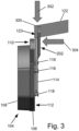
- Fig. 3 shows a combined view of a brake pad 104 and the structural element 122.
- the V-shaped tensioning structure 202 contacts a wedge-shaped surface 300 on the structural element 122. This in general exerts a downward force in direction 302 that holds the brake pad 106 in place.
- the arrow 304 indicates the direction of force from the brake caliper. Because the downward force is exerted in the direction 302, the retraction spring 114 also functions as a Niederhaltefeder configured to hold the brake pad in the brake system 100. The downward force can also cause the retraction spring 114 to be pushed into the retraction spring holder.
- Fig. 4 illustrates a further example of a brake pad 400.
- Outer pins are configured to hold the retraction spring 114 by contacting the outer edge 210.
- the end stop pins 404 are configured for contacting the outer edge 210 and also restricting motion of the retraction spring 114 in the direction 302 indicated in Fig. 3 .
- Fig. 5 shows the same brake pad 400 but now as a brake pad assembly 500 with the retraction spring 114 installed by sliding it along an insertion direction 302.
- this insertion direction 302 is identical with the direction that the force 302 in Fig. 3 is exerted.
- the force from the V-shaped wedge 300 therefore will press the spring 114 into the end stops 404 and this force will hold the brake pad 106 in place when assembled in the brake system 100.
- Figs. 6 and 7 illustrate a further example of a brake pad 600.
- the brake pad itself 600 is depicted in Fig. 6 .
- Fig. 7 the retraction spring 114 has been installed to form a brake pad assembly 700.
- Figs. 8, 9 , and 10 illustrate a further example of a brake pad 800.
- Figs. 9 and 10 depict the brake pad 800 with a retraction spring 114 installed forming a brake pad assembly 900.
- Fig. 10 further shows a perspective view of the brake pad assembly 900 that illustrates how the outer pins 402, 404 contact the outer edge 210 of the retraction spring 114 and hold it.
- the pins 402, 404 can be seen as being cylindrically symmetric and having a side surface 1000 that contacts and holds the outer edge 210 of the retraction spring 114.
- Fig. 11 shows a cross sectional view of a retaining pin 118' that has been inserted into a pin mounting hole 1100 in the back surface 112 of the backing plate 106.
- the retaining pin 118' may be held in the pin mounting hole 1100 using an interference fit 1102.
- the retaining pin 118' is cylindrically symmetric about an axis of symmetry 1104 and has a side surface 1000 with a smooth concave profile that provides a matching profile 1106 with the circular profile 206 of the retraction spring 114.
- the matching profile 1106 is smooth.
- the side surface 1000 partially overhangs and under hangs the retraction spring 114 and precisely holds it a predefined distance 1108 above the back surface 112 of the backing plate 106.
- the predefined distance 1108 could be chosen such that the retraction spring is in contact with the back surface 112, however it may be advantageous to choose the predefined distance 1108 to be above the back surface 112 to reduce mechanical noise.
- Fig. 12 shows in a further cross sectional view an alternative retaining pin 118" design with a different design for the side surface 1000'.
- the smooth side surface 1000 shown in Fig. 11 there is an angled or notched profile which has been cut into the side surface 1000'.
- the side surface 1000' still contacts the retraction spring 114 in two places forming the matching profiles 1106 to securely hold the retraction spring 114 at the predefined distance 1108 above the back surface 112 of the backing plate 106.
- Fig. 13 illustrates an example of manufacturing a brake pad.
- a backing plate 106 is provided.
- the backing plate has a front surface 110 and a back surface 112.
- a friction pad 108 is attached to the front surface 110. This may be accomplished in several different ways.
- the friction pad 108 could be attached to the front surface 110 using an adhesive. Alternatively, the friction pad 108 could be formed on the front surface or fused to the front surface.
- multiple retaining pins 118, 118', 118"', 402, 404, 406 are attached to the back surface to form a retraction spring holder 116.
- the backing plate is stamped to form pin mounting holes 1100 in the back plate.
- the retaining pins 118, 118', 118"', 402, 404, 406 could for example be held in the pin mounting holes using an interference fit 1102.
- a brake pad assembly 500, 700, 900 may be manufactured by inserting a retraction spring into the retraction spring holder 116 formed by the retaining pins 118, 118', 118"', 402, 404, 406.
Landscapes
- Engineering & Computer Science (AREA)
- General Engineering & Computer Science (AREA)
- Mechanical Engineering (AREA)
- Braking Arrangements (AREA)
Priority Applications (2)
| Application Number | Priority Date | Filing Date | Title |
|---|---|---|---|
| EP21201124.1A EP4163512A1 (fr) | 2021-10-06 | 2021-10-06 | Plaquette de frein |
| PCT/EP2022/077802 WO2023057562A1 (fr) | 2021-10-06 | 2022-10-06 | Plaquette de frein |
Applications Claiming Priority (1)
| Application Number | Priority Date | Filing Date | Title |
|---|---|---|---|
| EP21201124.1A EP4163512A1 (fr) | 2021-10-06 | 2021-10-06 | Plaquette de frein |
Publications (1)
| Publication Number | Publication Date |
|---|---|
| EP4163512A1 true EP4163512A1 (fr) | 2023-04-12 |
Family
ID=78085498
Family Applications (1)
| Application Number | Title | Priority Date | Filing Date |
|---|---|---|---|
| EP21201124.1A Pending EP4163512A1 (fr) | 2021-10-06 | 2021-10-06 | Plaquette de frein |
Country Status (2)
| Country | Link |
|---|---|
| EP (1) | EP4163512A1 (fr) |
| WO (1) | WO2023057562A1 (fr) |
Citations (3)
| Publication number | Priority date | Publication date | Assignee | Title |
|---|---|---|---|---|
| US20080110703A1 (en) * | 2005-01-18 | 2008-05-15 | Manfred Reuter | Partially Lined Disk Brake |
| DE102018221311A1 (de) * | 2017-12-12 | 2019-06-13 | Continental Teves Ag & Co. Ohg | Rückstellbefederungssystem für eine Scheibenbremse sowie Bremsbelag mit Lüftspielfeder |
| WO2020125954A1 (fr) | 2018-12-18 | 2020-06-25 | Volvo Truck Corporation | Agencement de frein de roue |
-
2021
- 2021-10-06 EP EP21201124.1A patent/EP4163512A1/fr active Pending
-
2022
- 2022-10-06 WO PCT/EP2022/077802 patent/WO2023057562A1/fr not_active Ceased
Patent Citations (3)
| Publication number | Priority date | Publication date | Assignee | Title |
|---|---|---|---|---|
| US20080110703A1 (en) * | 2005-01-18 | 2008-05-15 | Manfred Reuter | Partially Lined Disk Brake |
| DE102018221311A1 (de) * | 2017-12-12 | 2019-06-13 | Continental Teves Ag & Co. Ohg | Rückstellbefederungssystem für eine Scheibenbremse sowie Bremsbelag mit Lüftspielfeder |
| WO2020125954A1 (fr) | 2018-12-18 | 2020-06-25 | Volvo Truck Corporation | Agencement de frein de roue |
Also Published As
| Publication number | Publication date |
|---|---|
| WO2023057562A1 (fr) | 2023-04-13 |
Similar Documents
| Publication | Publication Date | Title |
|---|---|---|
| US10563713B2 (en) | Disc brake for a commercial vehicle and brake pad set | |
| EP1448911B1 (fr) | Frein a disques dote d'une pince elastique | |
| US10801565B2 (en) | Disc brake for a utility vehicle, and brake pad set | |
| US9388869B2 (en) | Disk brake | |
| JP6474387B2 (ja) | 自動車、特に商用車のキャリパ式ディスクブレーキ及びこのようなブレーキの押さえ装置 | |
| BRPI0720892A2 (pt) | Freio de disco, especialmente para veículo utilitário | |
| US10174799B2 (en) | Disk brake | |
| AU2016354121B2 (en) | Disc brake and set of brake pads | |
| US7810617B2 (en) | Friction element and disc brake | |
| EP4107405B1 (fr) | Système de retenue de patin de frein, patin de frein et véhicule | |
| EP4163512A1 (fr) | Plaquette de frein | |
| US7178641B2 (en) | Automobile brake caliper for reducing noise | |
| CN115929817A (zh) | 用于盘式制动器组件的制动夹和装置 | |
| JP4881864B2 (ja) | 小形のキャリアを備えたディスクブレーキ | |
| US11946519B2 (en) | Disc brake device | |
| EP4069990B1 (fr) | Pince coulissante de frein optimisée en ébauche avec élément de rétraction actif | |
| CN115038891B (zh) | 车辆盘式制动器装置、制动片和车辆 | |
| KR20170083288A (ko) | 디스크 브레이크 | |
| KR20230067686A (ko) | 디스크 브레이크의 브레이크 인가 장치 | |
| US20220252120A1 (en) | Disc brake comprising at least one elastic return spring for a brake pad, elastic return spring, replacement kit and mounting method | |
| KR102945454B1 (ko) | 브레이크 패드를 리턴시키기 위한 리트랙션 스프링 및 이를 포함하는 브레이크 어셈블리 | |
| KR20230138982A (ko) | 패드 스프링 및 이를 구비하는 캘리퍼 브레이크 | |
| KR102957286B1 (ko) | 디스크 브레이크 시스템에서 사용하기 위한 브레이크 패드의 후퇴용 클립, 브레이크 패드 조립체, 및 플로팅 캘리퍼 브레이크 | |
| JPH11218165A (ja) | ディスクブレーキのブレーキパッド | |
| GB2361969A (en) | Resilient mounting for an axially moveable brake disc |
Legal Events
| Date | Code | Title | Description |
|---|---|---|---|
| PUAI | Public reference made under article 153(3) epc to a published international application that has entered the european phase |
Free format text: ORIGINAL CODE: 0009012 |
|
| STAA | Information on the status of an ep patent application or granted ep patent |
Free format text: STATUS: THE APPLICATION HAS BEEN PUBLISHED |
|
| AK | Designated contracting states |
Kind code of ref document: A1 Designated state(s): AL AT BE BG CH CY CZ DE DK EE ES FI FR GB GR HR HU IE IS IT LI LT LU LV MC MK MT NL NO PL PT RO RS SE SI SK SM TR |
|
| STAA | Information on the status of an ep patent application or granted ep patent |
Free format text: STATUS: REQUEST FOR EXAMINATION WAS MADE |
|
| 17P | Request for examination filed |
Effective date: 20231012 |
|
| RBV | Designated contracting states (corrected) |
Designated state(s): AL AT BE BG CH CY CZ DE DK EE ES FI FR GB GR HR HU IE IS IT LI LT LU LV MC MK MT NL NO PL PT RO RS SE SI SK SM TR |
|
| GRAP | Despatch of communication of intention to grant a patent |
Free format text: ORIGINAL CODE: EPIDOSNIGR1 |
|
| STAA | Information on the status of an ep patent application or granted ep patent |
Free format text: STATUS: GRANT OF PATENT IS INTENDED |
|
| INTG | Intention to grant announced |
Effective date: 20251014 |
|
| GRAS | Grant fee paid |
Free format text: ORIGINAL CODE: EPIDOSNIGR3 |
|
| GRAA | (expected) grant |
Free format text: ORIGINAL CODE: 0009210 |
|
| STAA | Information on the status of an ep patent application or granted ep patent |
Free format text: STATUS: THE PATENT HAS BEEN GRANTED |