EP4166744B1 - Absicherbare haustiertür - Google Patents
Absicherbare haustiertür Download PDFInfo
- Publication number
- EP4166744B1 EP4166744B1 EP22197568.3A EP22197568A EP4166744B1 EP 4166744 B1 EP4166744 B1 EP 4166744B1 EP 22197568 A EP22197568 A EP 22197568A EP 4166744 B1 EP4166744 B1 EP 4166744B1
- Authority
- EP
- European Patent Office
- Prior art keywords
- door
- pet
- frame
- hinge
- pet door
- Prior art date
- Legal status (The legal status is an assumption and is not a legal conclusion. Google has not performed a legal analysis and makes no representation as to the accuracy of the status listed.)
- Active
Links
Images


Classifications
-
- E—FIXED CONSTRUCTIONS
- E06—DOORS, WINDOWS, SHUTTERS, OR ROLLER BLINDS IN GENERAL; LADDERS
- E06B—FIXED OR MOVABLE CLOSURES FOR OPENINGS IN BUILDINGS, VEHICLES, FENCES OR LIKE ENCLOSURES IN GENERAL, e.g. DOORS, WINDOWS, BLINDS, GATES
- E06B7/00—Special arrangements or measures in connection with doors or windows
- E06B7/28—Other arrangements on doors or windows, e.g. door-plates, windows adapted to carry plants, hooks for window cleaners
- E06B7/32—Serving doors; Passing-through doors ; Pet-doors
-
- E—FIXED CONSTRUCTIONS
- E06—DOORS, WINDOWS, SHUTTERS, OR ROLLER BLINDS IN GENERAL; LADDERS
- E06B—FIXED OR MOVABLE CLOSURES FOR OPENINGS IN BUILDINGS, VEHICLES, FENCES OR LIKE ENCLOSURES IN GENERAL, e.g. DOORS, WINDOWS, BLINDS, GATES
- E06B1/00—Border constructions of openings in walls, floors, or ceilings; Frames to be rigidly mounted in such openings
- E06B1/04—Frames for doors, windows, or the like to be fixed in openings
- E06B1/52—Frames specially adapted for doors
- E06B1/526—Frames specially adapted for doors for door wings that can be set up to open either left or right, outwards or inwards, e.g. provided with grooves for easily detachable hinges or latch plates
-
- E—FIXED CONSTRUCTIONS
- E06—DOORS, WINDOWS, SHUTTERS, OR ROLLER BLINDS IN GENERAL; LADDERS
- E06B—FIXED OR MOVABLE CLOSURES FOR OPENINGS IN BUILDINGS, VEHICLES, FENCES OR LIKE ENCLOSURES IN GENERAL, e.g. DOORS, WINDOWS, BLINDS, GATES
- E06B3/00—Window sashes, door leaves, or like elements for closing wall or like openings; Layout of fixed or moving closures, e.g. windows in wall or like openings; Features of rigidly-mounted outer frames relating to the mounting of wing frames
- E06B3/70—Door leaves
- E06B2003/7046—Door leaves with provisions for locks, hinges or other fittings
-
- E—FIXED CONSTRUCTIONS
- E06—DOORS, WINDOWS, SHUTTERS, OR ROLLER BLINDS IN GENERAL; LADDERS
- E06B—FIXED OR MOVABLE CLOSURES FOR OPENINGS IN BUILDINGS, VEHICLES, FENCES OR LIKE ENCLOSURES IN GENERAL, e.g. DOORS, WINDOWS, BLINDS, GATES
- E06B3/00—Window sashes, door leaves, or like elements for closing wall or like openings; Layout of fixed or moving closures, e.g. windows in wall or like openings; Features of rigidly-mounted outer frames relating to the mounting of wing frames
- E06B3/70—Door leaves
- E06B2003/7048—Door leaves with arcuate periphery; with openings having an arcuate periphery
-
- E—FIXED CONSTRUCTIONS
- E06—DOORS, WINDOWS, SHUTTERS, OR ROLLER BLINDS IN GENERAL; LADDERS
- E06B—FIXED OR MOVABLE CLOSURES FOR OPENINGS IN BUILDINGS, VEHICLES, FENCES OR LIKE ENCLOSURES IN GENERAL, e.g. DOORS, WINDOWS, BLINDS, GATES
- E06B3/00—Window sashes, door leaves, or like elements for closing wall or like openings; Layout of fixed or moving closures, e.g. windows in wall or like openings; Features of rigidly-mounted outer frames relating to the mounting of wing frames
- E06B3/70—Door leaves
- E06B2003/7057—Door leaves with little passing through doors
Definitions
- Doors are pathways to new places and spaces. Passing through a door may also allow a homeowner to get from one room of the house to another, or a professional to pass between rooms in an office. Passing through a door allows a traveler to leave a known area and venture into an unknown one. Equally as important, doors can be locked, offering security to the spaces they help define.
- An open door often implies a welcoming environment, while a closed door implies a desired environment of privacy or even secrecy.
- Doors come in a variety of shapes and sizes, to accommodate different kinds of travelers. Some are plain, some are decorated with ornate detail. A common festivity around the world is to seasonally decorate doors to celebrate sports teams, holidays, and other miscellaneous celebrations. Many doors can be replaced when after they accumulate significant wear and tear. Some doors have windows, are completely transparent, or can be incrementally opened, such as a Dutch door. Many doors open and close manually, but other doors may do these actions automatically, with the help of an activation button or motion sensor. However, these features are often lacking, if not completely absent, from the market for pet doors.
- Pet doors are often used internally and externally to help pet owners control how their pets navigate within and into or out of their homes. Pet doors may connect the inside of a home to the external elements, or may simply connect one room of a home to another. Due to their nature, pet doors are often hard to control once installed. The true users of pet doors are animals, who are unaware of proper door etiquette such as ensuring an exterior door is completely closed, so as to prevent a way of entry for bad actors or the elements.
- pet doors are hard to maintain, secure, and customize.
- Most pet doors available in the market today add to the amount of dirt being tracked into the home, do not completely close, and cannot be completely secured.
- pet owners who utilize pet doors often clean the area surrounding the installation area more, relying on third party equipment to close and secure the door when not in use, and needing to remember to subsequently remove any securing devices when the door is actually be used by a pet.
- Interior pet doors are often used to control a pet's access to certain areas inside the house.
- most pet doors are manually operated, should a pet door get stuck or break, the pet may be either deterred from further use or be injured in the process.
- GB 2 239 887 A discloses a pet door that has a frame for fitting into a door and defining an aperture, and a closure flap hung within the aperture that is pivoted about an axis that is offset inwardly of the top edge of the flap.
- a prop member is provided which in operative position is disposed to act between the flap in the region of said top edge thereof and the frame, whereby to hold the flap in an "open" position which allows a pet to pass freely through the aperture.
- a pet door comprising: a first frame, wherein the first frame is configured to partially embed within a first external surface; a hinge, wherein the hinge is configured to pivot along a pivot axis defined by the first frame; a door, wherein at least one edge connects to the hinge; a knob as later defined in this application, wherein the knob is attached to a surface of the door; a latch, wherein the latch interfaces with the first frame, wherein the second frame is configured to partially embed within a second external surface, wherein when the first frame and the second frame are embedded, a portal from the first external surface to the second external surface is created; and a second connector frame extending from the second frame, and wherein when connected, the second connector frame is configured to be fully embedded within the second external surface.
- the pet door may resemble a standard human door, with a knob, hinge, and windows, as non-limiting examples.
- the knob may comprise a latch for secure closing.
- the hinge may be inserted into a hinge recess so that the door may be securely locked in an open position. This removes the need to turn to third party locking mechanisms or systems to safely secure the pet door.
- the pet door may include a sliding mechanism to insert itself into a frame.
- the orientation of the knob to the door, the door to the frame, the hinge to the door and the frame, and the plurality of windows to the door may be predetermined or customizable. Having the ability to choose how these elements fit together, and even the option to change them later, allows the pet owner to truly customize the pet door system for their needs.
- the door may be open from, slide into, open up and out of, revolve within, or move in some other non-limiting equivalent way from or relative to the frame.
- the knob or door, or both may be interchangeable within the pet door system.
- the door may be replaced with a seasonal door during the relevant holiday or season. This would allow the pet owner to include the pet door system in the overall design and feel of their home, as opposed to being stuck with a pet door that may amount to no more than an eye sore.
- the frame may comprise a sensor.
- the sensor may interface with an external device, such as a doormat, to open and close the door automatically as a result of a change in motion, temperature, or other non-limiting sensible feature or method.
- the sensor may work in tandem with or separately from, or some combination thereof, with the external device to detect apet's presence and open or close the door, accordingly. This would enable the pet door system to be semi-automatic and responsive to the actions and presence of a pet, not just a pet owner. Pets would be able to operate this door themselves, without the aforementioned cleanliness and security repercussions. For example, the pet door may securely lock once the sensor no longer detects a pet trying to pass through.
- the present invention relates to a pet door according to claim 1, which includes a first frame, where the first frame is be configured to partially embed within a first external surface; a hinge, where the hinge is configured to pivot along a pivot axis defined by the first frame; a door, where at least one edge connects to the hinge; a knob, where the knob is attached to a surface of the door.
- the pet door includes a latch, where the latch extends from a rotational axis of the knob and interfaces with the first frame; a first connector frame extending from the first frame, where the first connector frame is configured to be fully embedded within the first external surface; a second frame, where the second frame is configured to partially embed within a second external surface, where when the first frame and the second frame are embedded, a portal from the first external surface to the second external surface is created; and a second connector frame extending from the second frame, where the second connector frame is connectable on a distal end to the first connector frame, and where when connected, the second connector frame is configured to be fully embedded within the second external surface.
- the pet door where the first frame may comprise a hinge recess that secures the hinge in a plurality of predetermined positions.
- the door may be secured in a fixed position by a door stopper.
- the door stopper may be attached to the first external surface and interfaces with a door edge.
- the door stopper may be attached to the first external surface and interfaces with the knob.
- the door stopper may be part of the first frame and interfaces with a door edge. In some embodiments, the door stopper may be part of the door and interfaces with a recess in the first frame.
- the frame may comprise a latch receiver configured to receive a latch extending from the door. In some aspects, the latch receiver may be internal to the first frame. In some embodiments, the latch receiver may be external and attached to the first frame. In some implementations, the door extends into a region between the first external surface and the second external surface.
- the first frame or second frame, or both, may comprise a sensor. In some embodiments, the sensor interacts with an external device. In some implementations, the first external surface may comprise a panel insertable proximate to a sliding glass door.
- a pet door may include a first recessed frame, where the first recessed frame may be configured to recess into a first external surface; a first hinge, where the hinge pivots along a pivot ax may be defined by a first side of the first recessed frame; a first door, where at least one edge connects to the first hinge; a first knob, where the first knob may be attached to a surface of the first door.
- the pet door includes a second hinge, where the hinge pivots along a pivot ax may be defined by a second side of the first recessed frame; a second door, where at least one edge connects to the first hinge.
- the pet door includes a second knob, where the second knob may be attached to a surface of the second door; a first connector frame, where the first connector frame may be attached to the first recessed frame; a second connector frame, where the second connector frame may be configured to connect to the first connector frame; and a second recessed frame configured to recess into a second external surface, where the second frame extends distally from the second connector frame and where when the first frame and the second frame are recessed, a portal from the first external surface to the second external surface may be created.
- the pet door may comprise a locking mechanism.
- the locking mechanism may comprise a latching mechanism located on the first knob and a positioning mechanism located proximate to the second knob, where the positioning mechanism may be configured to limit a position of the latching mechanism, and where the latching mechanism may be configured to fit over the second knob when in a locked position.
- the first door and the second door extend into a region between the first external surface and the second external surface.
- the first frame or the second frame, or both may comprise magnets for retaining one or both the first door and the second door in a fixed position.
- the external device controls a position of one or both the first door and the second door.
- the present disclosure provides generally for an installable, customizable, and securable pet door.
- the pet door may comprise a door, a knob, a plurality of windows, a frame, and a hinge.
- Knob refers to any kind of appendage that can be fixed on a door and turned, pulled, pushed, or moved in another non-limiting way to open and close the door.
- the knob may comprise a generic doorknob or any kind of handle, point, grip, sliding mechanism, or other non-limiting equivalent.
- the pet door may comprise a door, a knob, a plurality of windows, a frame, a hinge, a latch, a sensor, and other non-limiting features that may allow the pet door system to operate semi-automatically, securely open and close, and be better suited for safe use by a pet.
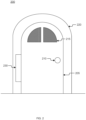
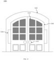
- the pet door 100 may comprise a door 105, a knob 110, a window 115, and a frame 120.
- the pet door 100 may be used to travel between two spaces separated by a barrier, such as a wall or door, by a pet 199.
- the pet 199 may be a large or small feline, canine, or other non-limiting examples.
- the door 105 may comprise plastic, vinyl, wooden, carpet, metallic, textured, hook-and-loop, or other non-limiting equivalent material.
- the door 105 may be customizable to match or complement the exterior or interior design of the pet 199 owner's home or room.
- the door 105 may comprise a material that allows seasonal decorations to be added or removed from the door 105.
- the door 105 may also be interchangeable, so the pet 199 owner has more than one option to choose from to match or complement the surrounding décor. This ability to alter the pet door 100 allows the pet 199 owner to fully incorporate the pet door 100 into their home.
- the knob 110 may resemble a generic doorknob, handle, bar, grip, fixture, or other non-limiting examples.
- the knob 110 may enable the pet 199 owner to securely close the pet door 100 when not in use.
- the knob may enable the pet 199 owner to open the pet door 100 with ease, as opposed to having to apply pressure to the pet door 100 itself, which may damage the pet door 100 if too much force is applied.
- the knob 110 may turn, push in and out, slide, or be static.
- the knob 110 may comprise the same or a different material than the door 105.
- the knob 110 may be interchangeable or removed entirely, depending on the pet 199 owner's preference.
- the window 115 may comprise a pane of glass, pane of plastic, pane of vinyl, some other non-limiting equivalent, or simply be an opening in the door 105.
- the window 115 may comprise one pane or a plurality of panes.
- the window 115 may allow the pet 199 owner to see through the pet door 100 if it is securely closed.
- the pet 199 may want to reenter the home through an exterior pet door 100.
- the window 115 would enable the pet 199 owner to keep the exterior pet door 100 closed while the pet 199 is not traveling through the door 105 and see the pet 199 waiting outside of the closed door 105.
- the window 115 may provide a barrier from external particles, dust, dirt, and other non-limiting examples from entering the interior of the passageway. The barrier may prevent tracking in dirt that is common with other pet doors.
- the door 105 may comprise more than one window 115.
- the window 115 may comprise a material that is translucent, frosted, textured, or some other non-limiting equivalent.
- the frame 120 may comprise the same or a different material than the door 105, the knob 110, the window 115, or some combination thereof. In some implementations, the frame 120 may align with the shape of the door 105. In other aspects, the frame 120 may comprise a different shape than the door 105. In some aspects, the frame 120 may insert into an exterior or interior wall or door so the pet door 100 may be used by a pet 199.
- the frame 120 may comprise an appendage or nodule that allows the door 105 to be secured in place, whether in a closed, completely open, or partially open position, to either the frame 120 or the wall the pet door 100 is inserted into.
- the frame 120 may comprise an extrusion that may prevent the door 105 from swinging in multiple directions within the frame 120.
- the door 105 may be limited to only swinging inside as opposed to outside by and within the frame 120. In some embodiments, this limit in the range of the door 105 may assist in aligning the latch of the door 105 to the corresponding slot in the frame. This may be a critical assistance when the latch and corresponding slot are sufficiently small to impede normal manual alignment. In some aspects, the frame 120 may allow the door 105 to open and close in multiple directions.
- the pet door 200 may comprise a door 205 and a knob 210.
- the pet door 200 may comprise a plurality of windows 215, a frame 220, and a hinge 230.
- the hinge 230 may couple to the door 205 and the frame 220, so the door 205 may open and close.
- the hinge may comprise a strap hinge, butt hinge, springloaded hinge, concealed hinge, piano hinge, offset hinge, overlay hinge, hidden barrel hinge, scissor hinge, gate hinge, or other non-limiting equivalents.
- the hinge 230 may be removeable, so a pet owner may customize the orientation and opening of the door 205. This may allow the pet owner to reuse the pet door 200 in a plurality of locations.
- the hinge 230 may be exposed or concealed by either the door 205 or frame 220, or both. The hinge 230 may allow the door 205 to be secured in a closed, completely open, or partially opened position, depending on the needs of the pet and the pet owner.
- the pet door 300 may comprise a door 305.
- the pet door 300 may comprise a knob 310.
- the pet door 300 may comprise a plurality of windows 315.
- the pet door 300 may comprise a frame 320, a recessed frame 325 coupled to the frame 320, and a hinge 330.
- the frame 320 may comprise a hinge recess 331. The hinge 330 may insert into the hinge recess 331 to secure the door 305 in an open position.
- the hinge recess 331 may be housed within the frame 320.
- the door 305 may begin in a closed position, aligned with the frame 320. When opened, the door 305 may be pushed toward the frame 320, prompting the hinge 330 to align with and insert into the hinge recess 331.
- the pet owner may have to perform an additional securing motion to prevent the door 305 from accidently clicking into a fixed position.
- This additional securing motion may involve lifting the door 305 up so that the hinge 330 uncouples from or misaligns with the hinge recess 331.
- the hinge recess 331 may be accessed at only one or a plurality of open positions.
- the hinge 330 and hinge recess 331 may be oriented vertically, as shown, or horizontally.
- the recessed frame 325 is coupled to the frame 320, providing stability when inserted into an exterior or interior wall or door for use.
- the recessed frame 325 may be the same or different size or shape from the frame 320 or door 305.
- the recessed frame 325 comprises the same or a different material from the frame 320 or the door 305.
- the recessed frame 325 may prevent tails or pet hair from being caught in the hollow cavity that may otherwise be exposed between the outer panels of a wall or door, allowing for safe, pain-free passage of the pet through the pet door 300.
- the recessed frame 325 may also allow for a snugger fit when the pet door 300 is installed.
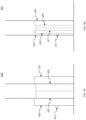
- the pet door 400 comprises a knob 410.
- the pet door 400 comprises a first frame 420 and a second frame 421.
- the pet door 400 also comprises a first connected frame 425 and a second connected frame 426.
- the first connected frame 425 may be coupled to the first frame 420 and the second connector frame 426 may be coupled between the first connected frame 425 and the second frame 421.
- This configuration may allow the pet door 400 to insert into an exterior or interior wall or door so that the first frame 420 and second frame 421 protrude from the opposing surfaces of the exterior or interior wall or door.
- the pet door 401 may comprise a knob 411, a first recessed frame 422, a second recessed frame 423, a first connector frame 427 coupled to the first recessed frame 422, and a second recessed frame 428 coupled between the first connector frame 427 and the second recessed frame 423.
- This configuration may allow the pet door 401 to insert into an exterior or interior wall or door so that the entire pet door 401, when closed, is at most flush with the existing exterior or interior wall or door.
- a pet door 400 may drop into a pocket where it can lock in place.
- an interior door in a home may slide into a pocket in the wall. If a pet owner wanted to install a pet door 400 to the interior door, the interior door may be unable to function normally. If a pet owner, however, installed a pet door 401 to the interior door, the door would still be able to slide into and out of the associated pocket in the wall.
- Figs. 5A-E an exemplary pet door 500, 501, 502 with a door stopper 540, 541, 550, 551 is shown.
- the pet door 500 may comprise a door 505, a knob 510, a plurality of windows 515, a frame 520, and a hinge 530.
- the frame 520 may comprise an interior door stopper 540.
- the interior door stopper 540, 541, 550, 551 may protrude from the frame 520 and catch the door 505, preventing it from fully closing. In some embodiments, the interior door stopper 540 may protrude from the door 505 and insert into a recess in the frame 520, securing the door 505 within the frame 520 when closed. In some aspects, the pet door 500, 501, 502 may interface with an external door stopper 541, 550, 551.
- the external door stopper 541 may align to a corner of the door 505 so when the door 505 is in its maximally opened position, the corner of the door 505 may rest on, couples to, or attaches to the external door stopper 541.
- the connection between the external door stopper 541 may be maintained by a lock-and-key mechanism, magnets, hook-and-loop fastener, adhesive material, or other non-limiting examples.
- the external door stopper 550, 551 may receive the knob 510 of the door 505 when the door 505 is in its maximally opened position. In some embodiments, the external door stopper 550, 551 may be sized to accommodate the knob 510. In some aspects, the connection between the external door stopper 550, 551 and the knob 510 may be maintained by a lock-and-key mechanism, magnets, hook-and-loop fastener, adhesive material, or other non-limiting examples.
- the external door stopper 550, 551 may couple to the same exterior or interior wall or door as the pet door 500, 501 is installed into at a predetermined distance from the pet door 500, 501 so the external door stopper 550, 551 may properly receive the knob 510. This may allow the pet owner to secure the door 505 in an open position, so the pet may pass freely through the pet door 500.
- the pet door 600 may comprise a door 605.
- the pet door 600 may comprise a knob 610.
- the pet door 600 may also comprise a one or more windows 615.
- the pet door 600 may comprise a frame 620.
- the pet door 600 may comprise a hinge 630.
- the knob 610 may comprise a locking mechanism.
- the locking mechanism may comprise a latch 660 and the frame 620 may comprise a latch receiver 665.
- the knob 610 may comprise a latch 660 that rotates and inserts into a latch receiver 665 to secure the door 605 in a completely closed position.
- the latch receiver 665 may be removable so that a pet owner could freely decide the orientation of the door 605 within the frame 620.
- the latch receiver 665 may couple to the frame 620, magnetically or by some other non-limiting adhesive, or be permanently carved into the frame 620.
- the latch 660 may be coupled to the knob 610, but this is not limiting.
- the latch 660 may be coupled to any part of the pet door 600 and the latch receiver may also be coupled to any part of the pet door 600 or located at some point near it for use.
- the latch 660 and corresponding latch receiver may allow the pet owner to secure the door 605 in a closed position when the pet door 600 is not in use by a pet, such as when the pet door 600 is an exterior pet door and the pet owner does not want dirt and other outside elements to be tracked or blown into their home.
- the sliding pet door 700, 701 may comprise a door 705, 706, a knob 711, 712, and a frame 720, 721.
- the sliding pet door 700 may comprise a plurality of windows 715.
- the sliding pet door 701 may comprise attachment mechanism 770 or an activation mechanism780, or both.
- the attachment mechanism 770 may comprise a plurality of magnets, a plurality of hook-and-loop closures, or other non-limiting equivalents.
- the activation mechanism 780 may comprise a doorbell.
- the door 705, 706 may slide into and out from the door frame 720, 721.
- the door 705, 706 may slide either horizontally or vertically.
- the door 705, 706 may be adjustable within the door frame 720, 721 to be able to slide both horizontally or vertically, depending on which mode is in use.
- the door fixture 711, 712 may secure the door 705, 706 in an open or closed position by coupling to opposite ends of the door frame 720, 721. This may allow the door 705, 706 to be secured in a preferred position based on the needs of the pet owner and the pet using the door 705, 706.
- the door 706 and the door frame 721 may comprise magnets 770 that couple together when the door 706 is in a partial or maximally open position. These magnets 770 may secure the door 706 in place, so the door 706 does not close on a pet travelling through.
- the door frame 721 may comprise an activation mechanism 780.
- the activation mechanism 780 may comprise a doorbell. The pet may be trained to use the activation mechanism 780, allowing the door 706 to be operated semi-automatically in response to the pet's stimulus.
- the pet door 800 may comprise a door 805.
- the pet door 800 may comprise a knob 810.
- the pet door 800 may comprise one or more windows 815.
- the pet door 800 may comprise a frame 820.
- the pet door may comprise a hinge 830.
- the hinge 830 may be arranged on the door 805 and the frame 820 so that the door 805 flips open either vertically or horizontally.
- the pet door 800 may interface with an interior or exterior household door, such as a cabinet door as a non-limiting example.
- the knob 810 may twist in order for the pet door 800 to be opened.
- the knob 810 may interact with an interior or exterior locking mechanism to secure the door 805 in the closed position.
- twisting the knob 810 for a certain number of degrees may secure the door 805 in a plurality of positions between a fully closed and a fully opened position, including the fully opened position.
- the knob 810 may pair with an interior knob 811. When twisted, the interior knob 811 may lock the door 805 in a fully opened position. This would allow for safe passage of the pet through the door 805 without clipping a tail or catching any fur, which may cause undue pain to the pet if these things occurred.
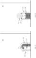
- the pet door 900 may be installed on an interior or exterior household door, such as a sliding or pocket door 990, as a non-limiting example.
- the pet door 900 may comprise a door 905 and a knob 910.
- the pet door 900 may comprise one or more windows 915, a frame 920, and a hinge 905.
- the pet door 900 may be completely flush to the paired household door, in order to allow the existing household door to function properly.
- the ability for the pet door 900 to be installed in a way in which the door 905 and frame 920 are completely flush with the sliding or pocket door 990 allows pet owners to install the pet door 900 in places otherwise previously unable to utilize a pet door.
- the revolving pet door 1000 may comprise a door 1005, a plurality of windows 1015, a frame 1020, and an axis 1030.
- the door 1005 may revolve about the axis 1030 within the frame 1020.
- the door 1005 and the frame 1020 may comprise paired magnets 1070 so the door 1005 may be secured in a completely closed position when not in use.
- the secured door 1005 allows the pet owner to control traffic flow of their pet or pets through the pet door 1000. For example, if the pet owner has guests over, they might not want their pet to travel through an interior or exterior pet door 1000 for security and sanitation purposes.
- the ability to secure the pet door in a closed position allows pet owners the ability to enable their pets to use the pet door 1000 as they prefer and need.
- the door 1005 may revolve about the axis 1030 in one or more directions.
- the revolving pet door 1000 may be installed in a panel accompanying an interior or exterior household door or on the interior or exterior household door, itself.
- the revolving pet door 1000 may be installed in a panel 1090 beside an exterior sliding glass door.
- the panel 1090 may allow for a secure seal with a sliding glass door without requiring cutting into the glass of the window. This installation method enables a pet owner to utilize the pet door 1000 in multiple scenarios, such as when they would like to install the pet door 1000 near a glass door in their home.
- the pet door 1000 enables simplified installation of a pet entry way near a specialty home door, such as a sliding glass, without disrupting the present configuration in a pet owner's home.
- exemplary pet door 1100, 1101, 1102, 1103 are shown.
- the pet door 1100, 1101, 1102, 1103 may comprise a door 1105, 1106, 1107, 1108.
- the pet door 1100, 1101, 1102, 1103 may comprise a knob 1110.
- the pet door 1100, 1101, 1102, 1103 may comprise one or more windows 1115.
- the pet door 1100, 1101, 1102, 1103 may comprise a frame 1120.
- the pet door 1100, 1101, 1102, and 1103 may comprise a hinge 1130.
- the pet door 1100 may detach from the hinge 1130 and be interchangeable within the frame with pet doors 1101, 1102, 1103. This may allow for pet owners to customize the appearance of the pet door 1100, 1101, 1102, 1103, such as in response to changing holiday seasons, as a non-limiting example.
- pet door 1100, 1101 may comprise an appearance similar to that of a standard household door and an interchangeable pet door 1102, 1103 may comprise an appearance relating to a particular season or holiday.
- the pet owner may choose to replace pet door 1100, 1101 with either 1102, 1103 or some other non-limiting embodiment so that the pet door 1102, 1103 coincides with the present season or holiday.
- the pet door 1200 may comprise a door 1205, a knob 1210, a plurality of windows 1215, a frame 1220, and a hinge 1230.
- the pet door 1200 may comprise a sensor 1295. This sensor may use a sensing technology, such as motion, infrared, temperature, or other non-limiting equivalent, to detect the presence of a pet.
- the sensor 1295 may open the door 1205 so the pet may pass through.
- the senor 1295 may also be also to sense once a pet has passed through the door, and after a predetermined or manually -programmed time period, the sensor 1295 may close the door 1205. This would allow the pet door 1200 to operate the door 1205 semi-automatically in response to a predetermined stimulus.
- the pet door 1200 may pair with an external device 1297, such as a doormat, that communicates with the sensor 1295, via a logical communication such as Bluetooth, so that when a pet applies pressure to the external device 1297, the sensor 1295 receives a signal to open the door 1205.
- an external device 1297 such as a doormat
- the sensor 1295 receives a signal to open the door 1205.
- the external device 1297 may communicate with the sensor 1295, which in turn may close the door 1205. Having the ability to program the time period during which the pet door 1200 may be opened, or the time it would take to open or close after being prompted by the pet owner, enables the pet door 1200 to operate semi-automatically.
- the external device 1297 may be programmable to accept a certain threshold of pressure to communicate with the sensor 1295. For example, if the pet weighs 4.5 Kg (10 pounds), the pet owner may program the external device 1297 to trigger the sensor 1295 when at least 0.9 Kg (2 pounds) of pressure is applied to the external device 1297.
- the senor 1295 may operate in tandem and separately from the external device 1297.
- the sensor 1295 may detect motion or utilize infrared technology in addition to receiving logical communication from the external device 1297 in order to open the door 1205. This would enable the pet door 1200 to open or close based on sensing the presence of a pet, or in response to a combination of stimulus provided by a trained pet, in order for the pet door 1200 to operate semi-automatically.
- the senor 1295 may also act as an attraction mechanism, drawing pets to the location of the door so that the pets may, over time, learn where the door is located and how to travel through it.
- This attraction mechanism may comprise a blinking light, a specialized sound emitter, or some other non-limiting equivalent that would attract, and not deter, a pet.
- a trained pet could learn to trigger the pet door 1200 to open and close, and in response the pet door 1200 may react semi-automatically depending on the stimulus.
- the senor 1295 may comprise a camera and a radiofrequency, Bluetooth, or another non-limiting signal that allows the pet door 1200 to communicate with a mobile device, such as a cell phone.
- the pet owner may download an application onto the cell phone for use with the pet door 1200.
- the sensor 1295 may sense the arrival or departure of a pet, inform the pet owner via the cell phone application, and allow the pet owner to remotely open or close the door 1205, accordingly. This may enable semi-automatic operation of the pet door 1200 via a smartphone application, motion or presence of a pet, a stimulus executed by a trained pet, and other combination of non-limiting equivalent examples.
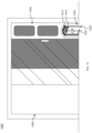
- a pet door 1300 may comprise double doors 1305 that may open by a hinge 1330.
- a pet door 1300 may comprise windows 1315 and door knobs 1310.
- the windows 1315 may be decorative, such as where they may not be transparent.
- double doors 1305 may be nested into an outer frame 1320, wherein the outer frame 1320 may be at least partially embedded into a surface, such as a door or wall.
- double doors 1305 may have a locking mechanism wherein the door may lock once both are closed together, such as illustrated in Figs. 14A-14D .
- a locking mechanism 1400 may comprise a latching mechanism 1410 and a positioning mechanism 1405.
- the positioning mechanism 1405 may limit the rotation of the latching mechanism 1410 to prevent or allow for locking.
- the positioning mechanism 1405 may be lifted to allow for the rotation of the latching mechanism 1410 onto the adjacent knob.
- a locking mechanism 1400 may allow for locking of double doors, such as illustrated, or locking of a door to a door frame, not illustrated.
Landscapes
- Engineering & Computer Science (AREA)
- Civil Engineering (AREA)
- Structural Engineering (AREA)
- Housing For Livestock And Birds (AREA)
- Power-Operated Mechanisms For Wings (AREA)
Claims (14)
- Haustierklappe (400), umfassend:einen ersten Rahmen (420), wobei der erste Rahmen (420) konfiguriert ist, um teilweise innerhalb einer ersten Außenoberfläche eingebettet zu sein;ein Scharnier, wobei das Scharnier konfiguriert ist, um entlang einer durch den ersten Rahmen definierten Schwenkachse zu schwenken;eine Klappe, wobei mindestens eine Kante mit dem Scharnier verbunden ist;einen Knopf (410), wobei der Knopf an einer Oberfläche der Klappe angebracht ist;einen Riegel, wobei sich der Riegel von einer Drehachse des Knopfs erstreckt und mit dem ersten Rahmen (420) über eine Schnittstelle verbunden ist;einen ersten Verbindungsrahmen (425), der sich von dem ersten Rahmen (420) erstreckt, wobei der erste Verbindungsrahmen (425) konfiguriert ist, um vollständig innerhalb der ersten Außenoberfläche eingebettet zu sein;einen zweiten Rahmen (421), wobei der zweite Rahmen (421) konfiguriert ist, um teilweise innerhalb einer zweiten Außenoberfläche eingebettet zu sein, wobei wenn der erste Rahmen (420) und der zweite Rahmen (421) eingebettet sind, ein Portal von der ersten Außenoberfläche zu der zweiten Außenoberfläche geschaffen wird; undeinen zweiten Verbindungsrahmen (426), der sich von dem zweiten Rahmen (421) erstreckt, wobei der zweite Verbindungsrahmen (426) an einem distalen Ende mit dem ersten Verbindungsrahmen (425) verbunden werden kann, und wobei der zweite Verbindungsrahmen (426), wenn er verbunden ist, konfiguriert ist, um vollständig innerhalb der zweiten Außenoberfläche eingebettet zu sein.
- Haustierklappe nach Anspruch 1, wobei der erste Rahmen (420) eine Scharnieraussparung umfasst, die das Scharnier in einer Vielzahl von vorherbestimmten Positionen sichert.
- Haustierklappe nach Anspruch 1, wobei die Klappe durch einen Klappenstopper (540) in einer festen Position gesichert ist.
- Haustierklappe nach Anspruch 3, wobei der Klappenstopper (540) an der ersten Außenoberfläche angebracht ist und mit einer Klappenkante über eine Schnittstelle verbunden ist.
- Haustierklappe nach Anspruch 3, wobei der Klappenstopper (540) an der ersten Außenoberfläche angebracht ist und mit dem Knopf über eine Schnittstelle verbunden ist.
- Haustierklappe nach Anspruch 3, wobei der Klappenstopper (540) Teil des ersten Rahmens ist und mit einer Klappenkante über eine Schnittstelle verbunden ist.
- Haustierklappe nach Anspruch 3, wobei der Klappenstopper (540) Teil der Klappe ist und mit einer Aussparung in dem ersten Rahmen über eine Schnittstelle verbunden ist.
- Haustierklappe nach Anspruch 1, wobei der erste Rahmen eine Riegelaufnahme (665) umfasst, die konfiguriert ist, um einen Riegel, der sich von der Klappe erstreckt, aufzunehmen.
- Haustierklappe nach Anspruch 8, wobei die Riegelaufnahme (665) im Inneren des ersten Rahmens ist.
- Haustierklappe nach Anspruch 8, wobei die Riegelaufnahme (665) außerhalb des ersten Rahmens ist und an diesem angebracht ist.
- Haustierklappe nach Anspruch 1, wobei sich die Klappe in einer Bereich zwischen der ersten Außenoberfläche und der zweiten Außenoberfläche erstreckt.
- Haustierklappe nach Anspruch 1, wobei der erste Rahmen oder der zweite Rahmen oder beide einen Sensor (1295) umfassen.
- Haustierklappe nach Anspruch 12, wobei der Sensor (1295) mit einer externen Vorrichtung interagiert.
- Haustierklappe nach Anspruch 1, wobei die erste Außenoberfläche eine Platte umfasst, die in der Nähe einer Glasschiebetür eingesetzt werden kann.
Applications Claiming Priority (1)
| Application Number | Priority Date | Filing Date | Title |
|---|---|---|---|
| US17/486,068 US11384595B1 (en) | 2021-09-27 | 2021-09-27 | Securable pet door |
Publications (4)
| Publication Number | Publication Date |
|---|---|
| EP4166744A2 EP4166744A2 (de) | 2023-04-19 |
| EP4166744A3 EP4166744A3 (de) | 2023-08-02 |
| EP4166744C0 EP4166744C0 (de) | 2024-09-04 |
| EP4166744B1 true EP4166744B1 (de) | 2024-09-04 |
Family
ID=82323857
Family Applications (1)
| Application Number | Title | Priority Date | Filing Date |
|---|---|---|---|
| EP22197568.3A Active EP4166744B1 (de) | 2021-09-27 | 2022-09-23 | Absicherbare haustiertür |
Country Status (4)
| Country | Link |
|---|---|
| US (1) | US11384595B1 (de) |
| EP (1) | EP4166744B1 (de) |
| CN (1) | CN115853407A (de) |
| ES (1) | ES2995207T3 (de) |
Families Citing this family (9)
| Publication number | Priority date | Publication date | Assignee | Title |
|---|---|---|---|---|
| USD998825S1 (en) * | 2021-08-03 | 2023-09-12 | Lisa Harrington | Pet door |
| US12435561B2 (en) * | 2021-09-27 | 2025-10-07 | Lisa E. Harrington | Securable pet door |
| US11702885B1 (en) * | 2022-06-09 | 2023-07-18 | Lisa Harrington | Securable pet door |
| US11788346B2 (en) * | 2021-09-27 | 2023-10-17 | Lisa Harrington | Securable pet door |
| US12203319B2 (en) * | 2021-09-27 | 2025-01-21 | Lisa Harrington | Securable pet door |
| US11859442B2 (en) * | 2022-02-09 | 2024-01-02 | In & Out Products, LLC | Door having an integrated pet travel door, a door panel having an integrated pet travel door, and a kit to retrofit an existing door |
| USD1098491S1 (en) * | 2024-04-11 | 2025-10-14 | Mingchang Zhou | Pet door |
| USD1093656S1 (en) * | 2024-05-09 | 2025-09-16 | Shenzhen Fengsheng Pet Products Co., Ltd. | Footprint screen pet door |
| CN119711911B (zh) * | 2024-12-03 | 2025-09-09 | 中国地质大学(武汉) | 一种智能宠物门及其识别系统 |
Family Cites Families (38)
| Publication number | Priority date | Publication date | Assignee | Title |
|---|---|---|---|---|
| US2758646A (en) * | 1952-12-04 | 1956-08-14 | Don D Johnson | Door structure |
| US3120032A (en) * | 1961-01-12 | 1964-02-04 | Robert W Burnette | Emergency escape |
| US3184803A (en) * | 1962-07-25 | 1965-05-25 | Stuart W Peel | Pet door |
| US3878645A (en) * | 1973-09-12 | 1975-04-22 | Robert C Porter | Pet door device |
| US4430836A (en) * | 1982-06-18 | 1984-02-14 | General Products Co., Inc. | Frame assembly for door light |
| US4468886A (en) * | 1983-06-29 | 1984-09-04 | Tew George A | Wall mountable safety hatch |
| GB2195690B (en) * | 1986-10-08 | 1990-04-25 | Anthony Green | Cat door |
| US4760872A (en) * | 1987-03-30 | 1988-08-02 | Hale Jr Seymour B | Security pet door |
| GB9000910D0 (en) * | 1990-01-16 | 1990-03-14 | Juggins Maurice | Pet doors |
| US5269097A (en) * | 1991-10-15 | 1993-12-14 | Davlantes George N | Pet access door frame modular unit |
| US5406748A (en) * | 1994-04-08 | 1995-04-18 | Davlantes; George N. | Vertically movable pet door flap |
| US5581940A (en) * | 1995-12-18 | 1996-12-10 | Randall R. Peterson | Dog door |
| US5735079A (en) * | 1996-02-01 | 1998-04-07 | Davlantes; George N. | Pet door assembly |
| US6385909B1 (en) * | 2000-07-31 | 2002-05-14 | Gary F. Marsh | Lockable, cammed door flap for pets |
| GB2381180B (en) * | 2001-10-24 | 2004-12-22 | David Chamberlain | Animal access system |
| US7207141B2 (en) * | 2004-09-10 | 2007-04-24 | Accession, Inc. | Sliding door insert for portable pet portal |
| CN101090629A (zh) * | 2004-11-23 | 2007-12-19 | 克拉西民俗公司 | 有活动装饰门框的宠物门 |
| US20070204514A1 (en) * | 2006-03-02 | 2007-09-06 | Radio Systems Corporation | Tunnel/wall unit |
| US7798103B2 (en) * | 2007-02-06 | 2010-09-21 | Radio Systems Corporation | Selective access electronic pet door |
| US7913454B2 (en) * | 2008-04-16 | 2011-03-29 | Accession, Inc. | Portable pet portal with three-position flap assembly |
| US8567137B2 (en) * | 2009-01-12 | 2013-10-29 | Accession, Inc. | Pet door panel storm window |
| GB2478571A (en) * | 2010-03-11 | 2011-09-14 | Tim Daniels | Door within a door |
| US8869458B2 (en) * | 2010-03-11 | 2014-10-28 | Ivm Homestyle Ltd. | Molded plastic access door |
| US8074606B1 (en) * | 2010-08-24 | 2011-12-13 | Schrey Thomas E | Plastic pet door assembly |
| DE102012203050A1 (de) * | 2012-02-28 | 2013-08-29 | Pabst Metallbau Gmbh | Hundeklappe |
| US8826594B2 (en) * | 2012-05-15 | 2014-09-09 | Radio Systems Corporation | Pet door with locking flaps |
| US8997400B2 (en) * | 2013-03-15 | 2015-04-07 | Anlin Industries | Low profile latch and closing panel for pet door |
| CN104653079A (zh) * | 2013-11-20 | 2015-05-27 | 陕西天豪科技发展有限公司 | 一种带宠物通道的指纹门 |
| CN105041165A (zh) * | 2015-08-21 | 2015-11-11 | 重庆钱珑门业有限责任公司 | 门 |
| CN206205702U (zh) * | 2016-08-30 | 2017-05-31 | 徐州今生缘门业有限公司 | 一种底部双向开合的多功能木门 |
| US10941611B2 (en) * | 2017-08-18 | 2021-03-09 | Radio Systems Corporation | Pet door |
| US11197463B2 (en) * | 2017-10-03 | 2021-12-14 | Dog-E-Door, Llc | Electronic and automatic pet door |
| CA3060142A1 (en) * | 2018-10-25 | 2020-04-25 | Larson Manufacturing Company Of South Dakota, Inc. | Two-piece door and installation system |
| US20200347669A1 (en) * | 2019-05-01 | 2020-11-05 | Lee W. Nickerson | Pet Door Security System |
| US11085234B2 (en) * | 2019-09-18 | 2021-08-10 | Morris Hunt | Secure in-door parcel receiving apparatus |
| US20210144956A1 (en) * | 2019-11-14 | 2021-05-20 | Derriss Bohannon | Animal door assembly and method of operation thereof |
| CN212406473U (zh) * | 2020-04-17 | 2021-01-26 | 湖南千房百计整体家居有限公司 | 一种提升推拉门 |
| CN113006669A (zh) * | 2021-02-24 | 2021-06-22 | 泉州市天创信息技术有限公司 | 一种新型一体化防盗门 |
-
2021
- 2021-09-27 US US17/486,068 patent/US11384595B1/en active Active
- 2021-10-09 CN CN202111175201.1A patent/CN115853407A/zh active Pending
-
2022
- 2022-09-23 ES ES22197568T patent/ES2995207T3/es active Active
- 2022-09-23 EP EP22197568.3A patent/EP4166744B1/de active Active
Also Published As
| Publication number | Publication date |
|---|---|
| EP4166744A3 (de) | 2023-08-02 |
| CN115853407A (zh) | 2023-03-28 |
| EP4166744A2 (de) | 2023-04-19 |
| ES2995207T3 (en) | 2025-02-07 |
| EP4166744C0 (de) | 2024-09-04 |
| US11384595B1 (en) | 2022-07-12 |
Similar Documents
| Publication | Publication Date | Title |
|---|---|---|
| EP4166744B1 (de) | Absicherbare haustiertür | |
| US11702885B1 (en) | Securable pet door | |
| US20230417099A1 (en) | Securable Pet Door | |
| US11788346B2 (en) | Securable pet door | |
| US5860465A (en) | Combined garage door screen and garage door and method | |
| US6675860B2 (en) | Window and door treatment complex | |
| KR101744888B1 (ko) | 창문의 잠금장치 | |
| US4995336A (en) | Animal entrance | |
| US4043079A (en) | Automatic latch door apparatus | |
| US12435561B2 (en) | Securable pet door | |
| US20260009287A1 (en) | Securable Pet Door | |
| KR102111354B1 (ko) | 유아 또는 애완동물용 안전문 | |
| KR100783420B1 (ko) | 미닫이 창문용 개폐구 | |
| CN208184537U (zh) | 智能感应子母门 | |
| CN216588344U (zh) | 一种功能可调式防盗门 | |
| JP2002115461A (ja) | ペット用ドアパネル | |
| KR102370917B1 (ko) | 공동주택 건축물의 다기능 현관문 | |
| KR200279141Y1 (ko) | 개문방향 선택형 여닫이문 구조 | |
| CN202611473U (zh) | 一种家居装饰门 | |
| KR20030091860A (ko) | 여닫이 도어용 고정금구 | |
| KR200200350Y1 (ko) | 슬라이딩 창호의 잠금장치 | |
| KR200350068Y1 (ko) | 현관문용 안전보조문 | |
| KR200377484Y1 (ko) | 방범창겸용 출입문 | |
| KR200192853Y1 (ko) | 미닫이 창문의 열림 제어장치 | |
| KR200362306Y1 (ko) | 옷장용 옷 물림 방지구 |
Legal Events
| Date | Code | Title | Description |
|---|---|---|---|
| PUAI | Public reference made under article 153(3) epc to a published international application that has entered the european phase |
Free format text: ORIGINAL CODE: 0009012 |
|
| STAA | Information on the status of an ep patent application or granted ep patent |
Free format text: STATUS: THE APPLICATION HAS BEEN PUBLISHED |
|
| AK | Designated contracting states |
Kind code of ref document: A2 Designated state(s): AL AT BE BG CH CY CZ DE DK EE ES FI FR GB GR HR HU IE IS IT LI LT LU LV MC MK MT NL NO PL PT RO RS SE SI SK SM TR |
|
| PUAL | Search report despatched |
Free format text: ORIGINAL CODE: 0009013 |
|
| AK | Designated contracting states |
Kind code of ref document: A3 Designated state(s): AL AT BE BG CH CY CZ DE DK EE ES FI FR GB GR HR HU IE IS IT LI LT LU LV MC MK MT NL NO PL PT RO RS SE SI SK SM TR |
|
| RIC1 | Information provided on ipc code assigned before grant |
Ipc: E06B 7/32 20060101AFI20230626BHEP |
|
| STAA | Information on the status of an ep patent application or granted ep patent |
Free format text: STATUS: REQUEST FOR EXAMINATION WAS MADE |
|
| 17P | Request for examination filed |
Effective date: 20231214 |
|
| RBV | Designated contracting states (corrected) |
Designated state(s): AL AT BE BG CH CY CZ DE DK EE ES FI FR GB GR HR HU IE IS IT LI LT LU LV MC MK MT NL NO PL PT RO RS SE SI SK SM TR |
|
| GRAP | Despatch of communication of intention to grant a patent |
Free format text: ORIGINAL CODE: EPIDOSNIGR1 |
|
| STAA | Information on the status of an ep patent application or granted ep patent |
Free format text: STATUS: GRANT OF PATENT IS INTENDED |
|
| INTG | Intention to grant announced |
Effective date: 20240325 |
|
| GRAS | Grant fee paid |
Free format text: ORIGINAL CODE: EPIDOSNIGR3 |
|
| GRAA | (expected) grant |
Free format text: ORIGINAL CODE: 0009210 |
|
| STAA | Information on the status of an ep patent application or granted ep patent |
Free format text: STATUS: THE PATENT HAS BEEN GRANTED |
|
| RAP3 | Party data changed (applicant data changed or rights of an application transferred) |
Owner name: HARRINGTON, LISA |
|
| RIN1 | Information on inventor provided before grant (corrected) |
Inventor name: HARRINGTON, LISA |
|
| AK | Designated contracting states |
Kind code of ref document: B1 Designated state(s): AL AT BE BG CH CY CZ DE DK EE ES FI FR GB GR HR HU IE IS IT LI LT LU LV MC MK MT NL NO PL PT RO RS SE SI SK SM TR |
|
| REG | Reference to a national code |
Ref country code: GB Ref legal event code: FG4D |
|
| REG | Reference to a national code |
Ref country code: CH Ref legal event code: EP |
|
| REG | Reference to a national code |
Ref country code: IE Ref legal event code: FG4D |
|
| REG | Reference to a national code |
Ref country code: DE Ref legal event code: R096 Ref document number: 602022005850 Country of ref document: DE |
|
| U01 | Request for unitary effect filed |
Effective date: 20240930 |
|
| U07 | Unitary effect registered |
Designated state(s): AT BE BG DE DK EE FI FR IT LT LU LV MT NL PT RO SE SI Effective date: 20241024 |
|
| PG25 | Lapsed in a contracting state [announced via postgrant information from national office to epo] |
Ref country code: NO Free format text: LAPSE BECAUSE OF FAILURE TO SUBMIT A TRANSLATION OF THE DESCRIPTION OR TO PAY THE FEE WITHIN THE PRESCRIBED TIME-LIMIT Effective date: 20241204 |
|
| PG25 | Lapsed in a contracting state [announced via postgrant information from national office to epo] |
Ref country code: GR Free format text: LAPSE BECAUSE OF FAILURE TO SUBMIT A TRANSLATION OF THE DESCRIPTION OR TO PAY THE FEE WITHIN THE PRESCRIBED TIME-LIMIT Effective date: 20241205 |
|
| PG25 | Lapsed in a contracting state [announced via postgrant information from national office to epo] |
Ref country code: HR Free format text: LAPSE BECAUSE OF FAILURE TO SUBMIT A TRANSLATION OF THE DESCRIPTION OR TO PAY THE FEE WITHIN THE PRESCRIBED TIME-LIMIT Effective date: 20240904 |
|
| U20 | Renewal fee for the european patent with unitary effect paid |
Year of fee payment: 3 Effective date: 20241224 |
|
| PG25 | Lapsed in a contracting state [announced via postgrant information from national office to epo] |
Ref country code: NO Free format text: LAPSE BECAUSE OF FAILURE TO SUBMIT A TRANSLATION OF THE DESCRIPTION OR TO PAY THE FEE WITHIN THE PRESCRIBED TIME-LIMIT Effective date: 20241204 Ref country code: HR Free format text: LAPSE BECAUSE OF FAILURE TO SUBMIT A TRANSLATION OF THE DESCRIPTION OR TO PAY THE FEE WITHIN THE PRESCRIBED TIME-LIMIT Effective date: 20240904 Ref country code: GR Free format text: LAPSE BECAUSE OF FAILURE TO SUBMIT A TRANSLATION OF THE DESCRIPTION OR TO PAY THE FEE WITHIN THE PRESCRIBED TIME-LIMIT Effective date: 20241205 |
|
| REG | Reference to a national code |
Ref country code: ES Ref legal event code: FG2A Ref document number: 2995207 Country of ref document: ES Kind code of ref document: T3 Effective date: 20250207 |
|
| PG25 | Lapsed in a contracting state [announced via postgrant information from national office to epo] |
Ref country code: IS Free format text: LAPSE BECAUSE OF FAILURE TO SUBMIT A TRANSLATION OF THE DESCRIPTION OR TO PAY THE FEE WITHIN THE PRESCRIBED TIME-LIMIT Effective date: 20250104 |
|
| PG25 | Lapsed in a contracting state [announced via postgrant information from national office to epo] |
Ref country code: SM Free format text: LAPSE BECAUSE OF FAILURE TO SUBMIT A TRANSLATION OF THE DESCRIPTION OR TO PAY THE FEE WITHIN THE PRESCRIBED TIME-LIMIT Effective date: 20240904 |
|
| PG25 | Lapsed in a contracting state [announced via postgrant information from national office to epo] |
Ref country code: PL Free format text: LAPSE BECAUSE OF FAILURE TO SUBMIT A TRANSLATION OF THE DESCRIPTION OR TO PAY THE FEE WITHIN THE PRESCRIBED TIME-LIMIT Effective date: 20240904 Ref country code: CZ Free format text: LAPSE BECAUSE OF FAILURE TO SUBMIT A TRANSLATION OF THE DESCRIPTION OR TO PAY THE FEE WITHIN THE PRESCRIBED TIME-LIMIT Effective date: 20240904 |
|
| PG25 | Lapsed in a contracting state [announced via postgrant information from national office to epo] |
Ref country code: SK Free format text: LAPSE BECAUSE OF FAILURE TO SUBMIT A TRANSLATION OF THE DESCRIPTION OR TO PAY THE FEE WITHIN THE PRESCRIBED TIME-LIMIT Effective date: 20240904 |
|
| PG25 | Lapsed in a contracting state [announced via postgrant information from national office to epo] |
Ref country code: RS Free format text: LAPSE BECAUSE OF FAILURE TO SUBMIT A TRANSLATION OF THE DESCRIPTION OR TO PAY THE FEE WITHIN THE PRESCRIBED TIME-LIMIT Effective date: 20240904 |
|
| PG25 | Lapsed in a contracting state [announced via postgrant information from national office to epo] |
Ref country code: MC Free format text: LAPSE BECAUSE OF FAILURE TO SUBMIT A TRANSLATION OF THE DESCRIPTION OR TO PAY THE FEE WITHIN THE PRESCRIBED TIME-LIMIT Effective date: 20240904 |
|
| PLBE | No opposition filed within time limit |
Free format text: ORIGINAL CODE: 0009261 |
|
| STAA | Information on the status of an ep patent application or granted ep patent |
Free format text: STATUS: NO OPPOSITION FILED WITHIN TIME LIMIT |
|
| PG25 | Lapsed in a contracting state [announced via postgrant information from national office to epo] |
Ref country code: IE Free format text: LAPSE BECAUSE OF NON-PAYMENT OF DUE FEES Effective date: 20240923 |
|
| 26N | No opposition filed |
Effective date: 20250605 |
|
| U21 | Renewal fee for the european patent with unitary effect paid with additional fee |
Year of fee payment: 4 Effective date: 20251007 |
|
| PG25 | Lapsed in a contracting state [announced via postgrant information from national office to epo] |
Ref country code: CY Free format text: LAPSE BECAUSE OF FAILURE TO SUBMIT A TRANSLATION OF THE DESCRIPTION OR TO PAY THE FEE WITHIN THE PRESCRIBED TIME-LIMIT; INVALID AB INITIO Effective date: 20220923 |
|
| PGFP | Annual fee paid to national office [announced via postgrant information from national office to epo] |
Ref country code: ES Payment date: 20251223 Year of fee payment: 4 |
|
| PG25 | Lapsed in a contracting state [announced via postgrant information from national office to epo] |
Ref country code: HU Free format text: LAPSE BECAUSE OF FAILURE TO SUBMIT A TRANSLATION OF THE DESCRIPTION OR TO PAY THE FEE WITHIN THE PRESCRIBED TIME-LIMIT; INVALID AB INITIO Effective date: 20220923 |