EP4174285A1 - Spiralvakuumpumpe - Google Patents
Spiralvakuumpumpe Download PDFInfo
- Publication number
- EP4174285A1 EP4174285A1 EP22216217.4A EP22216217A EP4174285A1 EP 4174285 A1 EP4174285 A1 EP 4174285A1 EP 22216217 A EP22216217 A EP 22216217A EP 4174285 A1 EP4174285 A1 EP 4174285A1
- Authority
- EP
- European Patent Office
- Prior art keywords
- wall
- seal
- recess
- axial direction
- vacuum pump
- Prior art date
- Legal status (The legal status is an assumption and is not a legal conclusion. Google has not performed a legal analysis and makes no representation as to the accuracy of the status listed.)
- Granted
Links
Images


Classifications
-
- F—MECHANICAL ENGINEERING; LIGHTING; HEATING; WEAPONS; BLASTING
- F01—MACHINES OR ENGINES IN GENERAL; ENGINE PLANTS IN GENERAL; STEAM ENGINES
- F01C—ROTARY-PISTON OR OSCILLATING-PISTON MACHINES OR ENGINES
- F01C19/00—Sealing arrangements in rotary-piston machines or engines
- F01C19/005—Structure and composition of sealing elements such as sealing strips, sealing rings and the like; Coating of these elements
-
- F—MECHANICAL ENGINEERING; LIGHTING; HEATING; WEAPONS; BLASTING
- F04—POSITIVE - DISPLACEMENT MACHINES FOR LIQUIDS; PUMPS FOR LIQUIDS OR ELASTIC FLUIDS
- F04C—ROTARY-PISTON, OR OSCILLATING-PISTON, POSITIVE-DISPLACEMENT MACHINES FOR LIQUIDS; ROTARY-PISTON, OR OSCILLATING-PISTON, POSITIVE-DISPLACEMENT PUMPS
- F04C18/00—Rotary-piston pumps specially adapted for elastic fluids
- F04C18/02—Rotary-piston pumps specially adapted for elastic fluids of arcuate-engagement type, i.e. with circular translatory movement of co-operating members, each member having the same number of teeth or tooth-equivalents
- F04C18/0207—Rotary-piston pumps specially adapted for elastic fluids of arcuate-engagement type, i.e. with circular translatory movement of co-operating members, each member having the same number of teeth or tooth-equivalents both members having co-operating elements in spiral form
- F04C18/0215—Rotary-piston pumps specially adapted for elastic fluids of arcuate-engagement type, i.e. with circular translatory movement of co-operating members, each member having the same number of teeth or tooth-equivalents both members having co-operating elements in spiral form where only one member is moving
- F04C18/0223—Rotary-piston pumps specially adapted for elastic fluids of arcuate-engagement type, i.e. with circular translatory movement of co-operating members, each member having the same number of teeth or tooth-equivalents both members having co-operating elements in spiral form where only one member is moving with symmetrical double wraps
-
- F—MECHANICAL ENGINEERING; LIGHTING; HEATING; WEAPONS; BLASTING
- F04—POSITIVE - DISPLACEMENT MACHINES FOR LIQUIDS; PUMPS FOR LIQUIDS OR ELASTIC FLUIDS
- F04C—ROTARY-PISTON, OR OSCILLATING-PISTON, POSITIVE-DISPLACEMENT MACHINES FOR LIQUIDS; ROTARY-PISTON, OR OSCILLATING-PISTON, POSITIVE-DISPLACEMENT PUMPS
- F04C18/00—Rotary-piston pumps specially adapted for elastic fluids
- F04C18/02—Rotary-piston pumps specially adapted for elastic fluids of arcuate-engagement type, i.e. with circular translatory movement of co-operating members, each member having the same number of teeth or tooth-equivalents
- F04C18/0207—Rotary-piston pumps specially adapted for elastic fluids of arcuate-engagement type, i.e. with circular translatory movement of co-operating members, each member having the same number of teeth or tooth-equivalents both members having co-operating elements in spiral form
- F04C18/0246—Details concerning the involute wraps or their base, e.g. geometry
- F04C18/0269—Details concerning the involute wraps
- F04C18/0284—Details of the wrap tips
-
- F—MECHANICAL ENGINEERING; LIGHTING; HEATING; WEAPONS; BLASTING
- F04—POSITIVE - DISPLACEMENT MACHINES FOR LIQUIDS; PUMPS FOR LIQUIDS OR ELASTIC FLUIDS
- F04C—ROTARY-PISTON, OR OSCILLATING-PISTON, POSITIVE-DISPLACEMENT MACHINES FOR LIQUIDS; ROTARY-PISTON, OR OSCILLATING-PISTON, POSITIVE-DISPLACEMENT PUMPS
- F04C25/00—Adaptations of pumps for special use of pumps for elastic fluids
- F04C25/02—Adaptations of pumps for special use of pumps for elastic fluids for producing high vacuum
-
- F—MECHANICAL ENGINEERING; LIGHTING; HEATING; WEAPONS; BLASTING
- F04—POSITIVE - DISPLACEMENT MACHINES FOR LIQUIDS; PUMPS FOR LIQUIDS OR ELASTIC FLUIDS
- F04C—ROTARY-PISTON, OR OSCILLATING-PISTON, POSITIVE-DISPLACEMENT MACHINES FOR LIQUIDS; ROTARY-PISTON, OR OSCILLATING-PISTON, POSITIVE-DISPLACEMENT PUMPS
- F04C27/00—Sealing arrangements in rotary-piston pumps specially adapted for elastic fluids
- F04C27/005—Axial sealings for working fluid
-
- F—MECHANICAL ENGINEERING; LIGHTING; HEATING; WEAPONS; BLASTING
- F04—POSITIVE - DISPLACEMENT MACHINES FOR LIQUIDS; PUMPS FOR LIQUIDS OR ELASTIC FLUIDS
- F04C—ROTARY-PISTON, OR OSCILLATING-PISTON, POSITIVE-DISPLACEMENT MACHINES FOR LIQUIDS; ROTARY-PISTON, OR OSCILLATING-PISTON, POSITIVE-DISPLACEMENT PUMPS
- F04C2220/00—Application
- F04C2220/10—Vacuum
Definitions
- the invention relates to a vacuum pump, in particular a scroll vacuum pump.
- a scroll vacuum pump is a positive displacement pump that compresses against atmospheric pressure and can be used, among other things, as a compressor.
- a scroll vacuum pump is known from the publication, for example EP 3 153 706 B1 known.
- Scroll vacuum pumps are also referred to as spiral vacuum pumps or spiral fluid conveying devices and can be used to generate a vacuum on a recipient connected to the gas inlet.
- the pumping principle on which a scroll vacuum pump is based is known from the prior art and is explained below.
- a pump stage of a scroll vacuum pump has two nested, for example Archimedean spiral cylinders, which are also referred to below as spiral elements.
- Each spiral element consists of a wall which extends in an axial direction from a carrier and which has a free end face facing away from the carrier.
- the spiral elements are plugged into one another in such a way that the spiral elements partially enclose crescent-shaped volumes.
- One spiral is fixed, while the other spiral can be moved on a circular path via an eccentric drive.
- the movable spiral thus performs a so-called centrally symmetrical oscillation, which is also referred to as "wobbling".
- a crescent-shaped volume trapped between the scroll cylinders travels within the scroll elements during sweeping of the movable scroll, causing gas from a radially outer gas inlet is promoted radially inward to a gas outlet lying in the middle of the spiral.
- Fluids such as fats or oils can generally be used to seal a pumping chamber of vacuum pumps.
- a piston pump for example, basically has a gap between the delivery chamber and the piston. In a fluid-sealed or fluid-lubricated design, this gap is filled by a fluid, usually oil or grease, during operation of the pump, with the fluid acting as a seal between the piston and the pumping chamber.
- a fluid usually oil or grease
- the disadvantage of such pumps is that the media conveyed by the pump, such as gases or vapors, can react with the fluids used as a seal, which can reduce the sealing effect in particular.
- the pamphlet EP 3 153 706 B1 discloses, for example, a seal disposed on a free face of a wall of a scroll member.
- the disadvantage of such sliding or rubbing seals is that they are usually subject to wear due to the constant sliding friction and often only have a limited service life.
- the pressure difference between adjacent delivery chambers generates a force which causes the movable seal in the recess to be pressed sideways and upwards against a surface of the other carrier.
- the sloping inner wall of the recess and the sloping side wall of the seal work together.
- this geometry makes it possible for the seal to protrude further out of the recess when it is subjected to abrasion, ie automatic abrasion compensation takes place.
- the seal is secured in the recess, for example in a pre-assembly state or in a rest state.
- the inner wall is inclined such that the inner wall converges towards the free end face of the wall, so that the recess narrows or narrows towards its opening.
- the recess can be delimited laterally by a first inner wall and a second inner wall, both of which run obliquely to the axial direction at least in sections, preferably continuously.
- both inner walls converge, or in other words, the two inner walls run towards one another, so that the recess narrows more and more from its bottom to its opening.
- the two side walls of the seal can also run obliquely to the axial direction at least in sections, preferably continuously.
- the two side walls converge, so that the seal narrows or tapers towards the top in its assembled position.
- Both spiral elements preferably have a recess and seal of the type described above.
- the first free end face of the first wall and the second free end face of the second wall each have a recess, in particular a groove, extending in the longitudinal direction of the wall, in which at least one seal is movably arranged in each case, with at least one inner wall of the respective recess runs obliquely to the corresponding axial direction and the inner wall is designed to cooperate with a side wall of the respective seal which runs obliquely to the axial direction.
- an inclination of the inner wall to the axial direction can vary in the longitudinal direction and/or an inclination of the side wall to the axial direction can vary in the longitudinal direction.
- an inclination of the inner wall to the axial direction can vary in the axial direction and/or an inclination of the side wall to the axial direction can vary in the axial direction, whereby the force distribution on the seal can be set even more precisely and adapted to the operating conditions.
- the inclination of the inner wall of the recess can essentially correspond to the inclination of the side wall of the seal.
- a maximum horizontal extent of the seal can be greater than a width of the opening of the recess and/or a maximum axial extent of the seal can be greater than a depth of the be recess.
- At least one elastic prestressing means for prestressing the seal in a direction from the bottom of the recess to the opening of the recess can be arranged between an underside of the seal and a bottom of the recess. This enables, among other things, an improvement in the sealing effect and an acceleration of the running-in or grinding-in process of the seal.
- At least one inner wall of the recess which interacts with the seal during operation of the vacuum pump, can be structured at least in sections.
- the inner wall can have indentations and/or elevations. Due to the structuring of the inner wall, the seal adheres better the inner wall. This in turn allows better fixation of the gasket in its exposed condition, ie in a condition in which the top of the gasket is pressed against a surface of an opposing carrier and in which a part of the gasket protrudes from the recess.
- the seal can have structured side walls.
- the seal may have a trapezoidal cross-section.
- the seal may have a cross-section in the form of an isosceles trapezium.
- the area of the seal in contact with the carrier increases with increasing abrasion, while the force acting on the seal remains essentially constant due to a pressure difference between adjacent conveying chambers.
- the resulting lower contact pressure per unit area ensures reduced abrasion, while the sealing effect remains sufficiently good due to the enlarged sealing surface.
- the seal can be designed in two or more parts.
- the seal can be designed in two or more parts in the longitudinal direction and/or in a radial direction of the spiral elements.
- the parts of the seal can have connecting means for connecting the parts.
- the connecting means can act in a form-fitting manner.
- the connecting means include tongue and groove.
- a configuration is also possible in which a part of the wall having the first inner wall is longer than a part of the wall having the second inner wall. This allows the seal to be easily tilted or screwed into the recess when it is installed.
- the seal can have cuts on its upper side and/or lower side and/or on one or both side walls.
- the cuts can be arranged at a distance from one another along the longitudinal direction and have an angle of inclination of less than 90°, preferably between 10 and 70°.
- the cuts form openings oriented towards the high pressure side, i.e. longitudinally towards the pump outlet.
- the vacuum pump according to the invention is characterized by an increased service life.
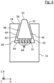
- FIG. 1 shows a vacuum pump designed as a scroll vacuum pump 10 .
- This includes a pump housing 40 in which an inlet 34 and an outlet 36 are provided. An outlet of a recipient (not shown) can be connected to the inlet 34 .
- a scroll pump stage 11 provided in the pump housing 40 can draw in a pump medium (gas or liquid) from the recipient through the inlet 34 and deliver it to the outlet 36 .
- the pumping stage 11 includes a first scroll element 12 and a second scroll element 20.
- the first scroll element 12 has a first wall 14 spiraling about a first axis and extending in an axial direction Z from a first support 16 and one of the first support 16 facing away from the first free end face 18 (see also 2 ).
- the second spiral element 20 also has a second wall 22 running spirally about a second axis, which extends in the axial direction Z from a second carrier 24 and has a second free end face 26 facing away from the second carrier 24 .
- the second carrier 24 of the second scroll member 20 is connected to the casing 40 and may be formed as a part of the pump casing 40 .
- the outlet 36 of the pump 10 extends axially through the fixed scroll member 20.
- the volute walls 14, 22 each have an end face 18, 26 on which a seal 32 is located. The seals 32 touch the respectively opposite carrier 24 or 16.
- a direction parallel to the shaft axis Aw is referred to as the axial direction Z.
- a direction that runs perpendicular to the axial direction Z is referred to as the radial direction R.
- a direction that runs along a respective wall 14, 22 of a spiral element 12, 22 runs, ie the longitudinal direction L runs in an XY plane of the pump 10 (cf. 2 ).
- the shaft 37 rotates and the eccentric shaft 35 connected thereto performs a revolving motion about the shaft axis Aw of the shaft 37.
- the spiral element 12 carries out a centrally symmetrical oscillating movement on a circular path around the shaft axis Aw.
- the spiral element 12 does not rotate about its own axis Ae, which is achieved by anti-rotation mechanisms known to those skilled in the art.
- This movement creates between the intermeshing spiral elements 12, 20 closed, crescent-shaped conveying chambers 28, which continue to reduce their volume towards the inside in the direction of the pump outlet 36. In this way, a gas sucked in via the inlet 34 is compressed.
- the shape of the conveying chambers 28 can be 2 recognize, which shows a section of a cross section perpendicular to the shaft 37 of a spiral pump 10.
- the cross-sectional plane (XY plane in the drawing) runs through the interlocking spiral walls 14, 22 of the spiral elements 12, 20.
- the pump 10 according to 1 has a movable spiral element 12, the carrier 16 of which is only provided with a spiral-shaped wall 14 on one side, this is a one-sided pumping system, which is also referred to as a single-wrap pumping system.
- the scroll vacuum pump 10 according to the invention can also be designed as a double-sided pump system.
- the orbiting scroll element of the double-sided embodiment has a carrier which is provided with spiral walls on both sides.
- Such a double-sided pump system is known, for example, from the publication EP 3 153 706 B1 known.
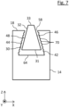
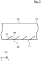
- FIG. 3 shows a detailed view of the scroll pump 10 1 , namely a section through the first wall 14 in the region of the first free end face 18.
- the first free end face 18 has a recess 30 extending in the longitudinal direction L of the wall 14.
- the recess 30 is designed as a groove or indentation, is delimited by two lateral inner walls 42, 44 and a base 64 and has an opening 58 with a width 56 at the top.
- the bottom 64 is formed parallel to the radial direction R.
- the side walls 46, 48 of the seal 32 run obliquely to the axial Z direction.
- the first side wall 46 has a first inclination 52a to the axial Z direction and the second side wall 48 has a second inclination 52b to the axial Z direction.
- the slopes 52a, 52b have equal amounts or angles, i.e. the seal 32 has the shape of an isosceles trapezium in cross section.
- the first and second slopes 52a, 52b have an angle between 10° and 60°, preferably between 25° and 45°. Due to the trapezoidal shape, the surface pressure on the upper side 33 of the seal 32 gradually decreases as the wear of the seal 32 progresses, as a result of which a reduction in the rate of wear can be achieved.
- the horizontal extent of the underside 31 of the seal 32 defines a maximum horizontal extent 54 of the seal 32 which is preferably greater than the width 56 of the opening 58 of the recess 30 .
- a maximum axial extension 60 of the seal 32 can be greater than a depth 62 of the recess 30 be.
- the part of the seal 32 which protrudes from the recess 30 during operation of the pump 10 can be adjusted by the choice of the aforementioned dimensions.
- the inner walls 42, 44 of the recess 30 also run obliquely to the axial direction Z.
- the first inner wall 42 has a first inclination 50a to the axial direction Z and the second inner wall 44 has a second inclination 50b to the axial direction Z, with the Inclinations 50a, 50b have the same amounts, i.e. the recess 30 tapers uniformly in the direction of its opening 58 (in the Z direction in 3 ).
- the first and second inclinations 50a, 50b have an angle between 10° and 60°, preferably between 25° and 45°.
- the inner walls 42, 44 of the recess 30 are each designed to interact with the side walls 46, 48 of the seal 32, which run obliquely to the axial direction Z.
- the pumping medium is compressed further and further towards the pump outlet 36 . Consequently, the closer they are to the pump outlet 36, the higher the pressure in the pumping chambers 28.
- a first delivery chamber 28a has a first pressure P1, the amount of which is greater than the amount of a second pressure P2 in an adjacent, second delivery chamber 28b, provided that the first delivery chamber 28a is closer to the outlet 36 than the second delivery chamber 28b.
- This pressure difference causes a force F to act on the seal 32 (cf. arrow in the lower left area of the recess).
- the slopes 50a, 50b of the two inner walls 42, 44 of the recess 30 have different amounts.
- the slopes 50a, 50b of the two inner walls 42, 44 of the recess 30 have different amounts.
- the slopes 50a, 50b of the two inner walls 42, 44 of the recess 30 have different amounts.
- the side 42 with the lower pressure runs obliquely to the axial direction Z, so that a part of the force F acting on the seal 32 is also transmitted to the oblique side wall 46 of the seal 32 here.
- the seal 32 has a cross-section in the shape of a right-angled trapezium.
- the inclination 50 of the inner wall 42, 44 varies in the longitudinal direction L.
- the inclination 50 of the inner wall 42, 44 in the longitudinal direction L can increase as the distance from the outlet 36 decreases.
- a design is possible in which only a longitudinal section of the recess 30 in the longitudinal direction L has an inclined inner wall 42, 44.
- the inclinations 50 of the inner wall 42, 44 can also vary in the axial direction Z.
- the inclination 50 of the inner wall 42, 44 in the axial direction Z can increase or decrease as the distance from the opening 58 of the recess 30 decreases.
- a portion of the inner wall 42, 44 near the bottom 64 of the recess 30 may have a smaller or greater slope 50 than a portion of the inner wall 42, 44 near the opening 58 of the recess 30, or vice versa.
- the slope 52 of the side wall 46, 48 of the seal 32 can be adapted to the slope 50 of the inner wall 42, 44 of the recess 30, i.e.
- the slope 52 of the side wall 46, 48 of the seal 32 can also be towards the axial direction Z in the axial vary in direction Z.
- the slope 50 of the inner wall 42, 44 can essentially correspond to the slope 52 of the side wall 46, 48. This allows different operational requirements to be addressed.
- the inclination 52 of the side wall 46, 48 of the seal 32 to the axial direction Z can vary in the longitudinal direction L and/or in the axial direction Z.
- the slope 50a, 50b of the inner wall 42, 44 preferably essentially corresponds to the slope 52 of the side wall 46, 48, i.e. the slope 52 of the side wall 46, 48 of the seal 32 is preferably complementary to the slope 50 of the inner wall 42 or 44 of the Recess 30. This ensures that the seal 32 rests optimally over the entire area on the inner wall 42, 44 during operation of the pump 10.
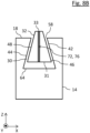
- the exemplary embodiment shown of a wall 14, 22 of a spiral element 12, 20 of a scroll vacuum pump 10 according to the invention differs from that in 3 shown essentially in that at least one elastic biasing means 66 for biasing the seal 32 in a direction from the bottom 64 of the recess 30 to the opening 58 of the recess 32 is arranged between the underside 31 of the seal 32 and the bottom 64 of the recess 30 ( in Z direction in 6 ).
- Biasing means 66 is five in springs 68 arranged next to one another in the radial direction R.
- the biasing means 66 can also include only one or any number of springs 68 .
- the springs 68 are symbolic here for any one-piece or multi-piece elastic element or a plurality of elastic elements.
- the prestressing means 66 has the effect, among other things, that the seal 32 is pressed against the surface 25 of the carrier 24 even when the pump 10 is at rest. This enables the grinding-in process of the seal 32 and thus the running-in process of the pump 10 to be accelerated.
- the inner walls 42, 44 of the recess 30 can be structured. At the in 7 In the embodiment shown, the inner walls 42, 44 have indentations 70 or grooves which are formed equidistantly along the respective inner wall 42, 44 and extend in the longitudinal direction L. In addition or as an alternative to this, the inner walls 42, 44 can also be structured with elevations (not shown) in the form of grooves and/or ribs and/or knobs extending in the longitudinal direction L. The depth or height of the structuring is adapted to the respective requirements, for example to the elasticity of the seal 32.
- the structuring can vary in the axial direction Z and/or in the longitudinal direction L of the recess 30 and/or can only be present in sections.
- a structuring is conceivable in which the density of the structuring increases the closer the respective section of the inner wall 42, 44 is to the opening 58 of the recess 30.
- the inner wall can also only be structured in sections, for example only in an upper third or an upper half of the inner wall 42, 44 near the opening 58. It is also understood that only one of the inner walls 42, 44 can be structured. In particular, only the inner wall 42 acted upon by the seal 32 during operation of the pump (see 4 ) be structured. The structuring of the inner wall 42, 44 enables the seal 32 to be better fixed in its operating state.
- the seal 32 consists of two parts arranged next to one another in the radial direction R.
- the seal 32 can also consist of two parts arranged one above the other in the axial direction Z (not shown). This enables the seal 32 to be easily introduced or fitted into the recess 30 since the parts of the seal 32 can be inserted into the recess 30 one after the other.
- the parts of the seal 32 can have connecting means 72 for connecting the parts so that the parts of the seal 32 do not slip against one another in the assembled state or a gap forms between the parts.
- the connecting means acts in a form-fitting manner.
- the connecting means 72 comprise a tongue and groove 74, so that when the seal 32 is assembled, the two parts can be connected by pressing one into the other.
- the positively acting connecting means 72 are not limited to tongue and groove 74, but can also include, for example, ribs and grooves that engage in one another (not shown).
- the two parts of the seal are arranged side by side in the radial direction R and each have a cross section in the form of an isosceles trapezium.
- a bonding agent 72 in the form of an adhesive 76, such as a resin or glue, which is applied to one or both of the parts when the gasket 32 is assembled.
- the adhesive 76 can also be dispensed with, so that the parts interact in a friction-locked manner.
- the embodiment shown has the seal 32 on its underside 31 incisions 78 which extend obliquely from the underside 31 into the seal 32 .
- the incisions 78 are arranged along the longitudinal direction L and have an angle of inclination 80 of less than 90°, preferably between 10° and 70°.
- the cuts or cuts 78 form apertures and lips or tabs 82 which are oriented or open toward the high pressure side, ie, toward the outlet 36 .
- the tabs 82 formed by the incisions 78 prevent a backflow between the underside 31 of the seal and the bottom 64 of the recess 30 in the longitudinal direction L of the recess 30.
- the tabs 82 - in addition or as an alternative to the prestressing means 66 (please refer 6 ) - provide an elastic pressing force.
- cuts 78 can be made in any of the sides 31, 33, 46, 48 of the seal 32.
- a part of the wall 14 having the first inner wall 42 is longer than a part of the wall 14 having the second inner wall 44.
- the embodiment shown in FIG 10 shown recess 30 from the Figures 3-8B shown in that it has a larger opening 58. This allows the seal 32 to be easily tilted or screwed into the recess.
- the sections of the wall 14 that have the inner walls 42, 44 are designed to be plastically deformable and initially form a groove that extends in the longitudinal direction L of the walls 14, 22 with inner walls 42, 44 that run parallel to the axial direction Z.
- seal 32 is inserted into the groove first (see dashed straight arrow). Since the opening of the groove is wider than the maximum horizontal extent 54 of the seal 32, the seal 32 can simply be pushed or plugged into the groove (assembly step (a)). Thereafter, the two sections of the wall 14 are bent inwards so that a recess 30 according to the invention is formed, in which the seal 32 is mounted (cf.
- the wall sections are preferably bent over by means of a flanging tool.
- the wall sections can be bent over the entire length of the spiral element 12, 20 or only in sections at regular or irregular intervals.
- only one of the sections of the wall 14 can be plastically deformable, while the opposite part has a sloping inner wall 44 or straight inner wall 44 (see FIG figure 5 ) so that only a section on one side of the wall 14 has to be bent over when the seal 32 is assembled.
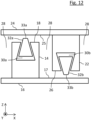
- both the first spiral element 12 and the second spiral element 20 of the pump stage 11 can be designed according to the invention.
- the first free end face 18 of the first wall 14 and the second free end face 26 of the second wall 22 each have a recess 30a, 30b extending in the longitudinal direction L of the wall, in which at least one seal 32a, 32b according to the invention is movably arranged .
- the seal on its upper side which interacts with the opposite carrier during operation of the pump, with a Material provided or covered that is softer than the material of the main body of the seal.
- the softer material quickly grinds in during the running-in or grinding-in process of the seal, so that this process is accelerated.
- the softer material is pasty. Both materials can be elastic.
Landscapes
- Engineering & Computer Science (AREA)
- Mechanical Engineering (AREA)
- General Engineering & Computer Science (AREA)
- Applications Or Details Of Rotary Compressors (AREA)
- Rotary Pumps (AREA)
Abstract
Description
- Die Erfindung betrifft eine Vakuumpumpe, insbesondere Scrollvakuumpumpe.
- Eine Scrollvakuumpumpe ist eine gegen Atmosphärendruck verdichtende Verdrängerpumpe, die sich unter anderem als Kompressor einsetzen lässt. Eine Scrollvakuumpumpe ist beispielsweise aus der Druckschrift
EP 3 153 706 B1 bekannt. - Scrollvakuumpumpen werden auch als Spiralvakuumpumpen oder Spiralfluidfördereinrichtungen bezeichnet und können zur Erzeugung eines Vakuums an einem einem an den Gaseinlass angeschlossenen Rezipienten verwendet werden. Das einer Scrollvakuumpumpe zugrunde liegende Pumpprinzip ist aus dem Stand der Technik bekannt und wird nachstehend erläutert. Eine Pumpstufe einer Scrollvakuumpumpe weist zwei ineinander gesteckte, beispielsweise archimedische Spiralzylinder auf, welche nachstehend auch als Spiralelemente bezeichnet werden. Jedes Spiralelement besteht dabei aus einer Wand, die sich in einer axialen Richtung von einem Träger erstreckt und die eine dem Träger abgewandte freie Stirnseite aufweist. Die Spiralelemente sind so ineinandergesteckt, dass die Spiralelemente abschnittsweise halbmondförmige Volumina umschließen. Dabei steht eine Spirale fest, während die andere Spirale über einen Exzenterantrieb auf einer kreisförmigen Bahn bewegt werden kann. Die bewegbare Spirale führt somit eine sogenannte zentralsymmetrische Oszillation aus, was auch als "wobbeln" bezeichnet wird. Ein zwischen den Spiralzylindern eingeschlossenes halbmondförmiges Volumen wandert während des Wobbelns der beweglichen Spirale innerhalb der Spiralelemente weiter, wodurch mittels des wandernden Volumens Gas von einem radial außen liegenden Gaseinlass nach radial innen zu einem in der Spiralenmitte liegenden Gasauslass gefördert wird.
- Zur Abdichtung eines Förderraumes von Vakuumpumpen können generell Fluide wie Fette oder Öle herangezogen werden. Eine Kolbenpumpe beispielsweise weist grundsätzlich einen Spalt zwischen dem Förderraum und dem Kolben auf. Dieser Spalt wird bei einer fluidgedichteten bzw. -geschmierten Ausführung während des Betriebs der Pumpe von einem Fluid, meist Öl oder Fett, gefüllt, wobei das Fluid als Dichtung zwischen dem Kolben und dem Förderraum wirkt. Nachteilig bei derartigen Pumpen ist, dass die mit der Pumpe geförderten Medien wie Gase oder Dämpfe mit den als Dichtung eingesetzten Fluiden reagieren können, was insbesondere die Dichtwirkung herabsetzen kann.
- Aus diesem Grund werden sogenannte trockene Lösungen bevorzugt, bei denen die geförderten Medien nicht mit Fluiden in Kontakt kommen. Hierbei werden grundsätzlich gleitende oder schleifende Dichtungen aus chemisch beständigen Materialien, üblicherweise Kunststoffe, eingesetzt.
- Zur Abdichtung der Förderräume von herkömmlichen Scrollvakuumpumpen sind an den Stirnseiten der Spiralwände jeweils Dichtungen vorgesehen. Die Druckschrift
EP 3 153 706 B1 offenbart beispielsweise eine Dichtung, die auf einer freien Stirnseite einer Wand eines Spiralelements angeordnet ist. Nachteilig bei derartigen gleitenden oder schleifenden Dichtungen ist, dass diese in der Regel, bedingt durch die ständige Gleitreibung, einem Verschleiß unterliegen und oft nur eine begrenzte Lebensdauer aufweisen. - Es ist daher eine Aufgabe der vorliegenden Erfindung, eine Vakuumpumpe mit einer verbesserten Lebensdauer bereitzustellen.
- Diese Aufgabe wird erfindungsgemäß durch eine Vakuumpumpe mit den Merkmalen des Anspruchs 1 und insbesondere dadurch gelöst, dass die Vakuumpumpe ein erstes Spiralelement, das eine spiralförmig um eine erste Achse verlaufende erste Wand aufweist, die sich in einer axialen Richtung von einem ersten Träger erstreckt und die eine dem ersten Träger abgewandte erste freie Stirnseite aufweist und ein zweites Spiralelement, das eine spiralförmig um eine zweite Achse verlaufende zweite Wand aufweist, die sich in der axialen Richtung von einem zweiten Träger erstreckt und die eine dem zweiten Träger abgewandte zweite freie Stirnseite aufweist, umfasst, wobei das erste Spiralelement und das zweite Spiralelement relativ zueinander bewegbar sind und derart angeordnet sind, dass die erste Wand und die zweite Wand unter Ausbildung von Förderräumen dichtend ineinandergreifen, die freie Stirnseite zumindest einer der Wände eine sich in einer Längsrichtung der Wand erstreckende Ausnehmung, insbesondere Nut, aufweist, in der zumindest eine Dichtung, bevorzugt zumindest teilweise - insbesondere vollständig - aus einem elastischen Material gefertigt, beweglich angeordnet ist, und die Ausnehmung seitlich von zumindest einer Innenwand begrenzt ist, die zumindest abschnittsweise, bevorzugt durchgehend schräg zu der axialen Richtung verläuft und die dazu ausgebildet ist, mit einer zumindest abschnittsweise, bevorzugt durchgehend schräg zu der axialen Richtung verlaufenden Seitenwand der Dichtung zusammenzuwirken.
- Im Betrieb der Pumpe wird durch den Druckunterschied zwischen benachbarten Förderräumen eine Kraft erzeugt, die bewirkt, dass die bewegliche Dichtung in der Ausnehmung zur Seite und nach oben gegen eine Oberfläche des anderen Trägers gedrückt wird. Dabei wirken die schräge Innenwand der Ausnehmung und die schräge Seitenwand der Dichtung zusammen. Diese Geometrie ermöglicht einerseits, dass die Dichtung weiter aus der Ausnehmung heraustreten kann, wenn sie Abrieb erfährt, d.h. es erfolgt eine automatische Abriebkompensation. Andererseits wird die Dichtung in der Ausnehmung gesichert, beispielsweise in einem Vormontagezustand oder in einem Ruhezustand.
- Insbesondere ist die Innenwand derart geneigt, dass die Innenwand in Richtung zu der freien Stirnseite der Wand konvergiert, sodass sich die Ausnehmung in Richtung ihrer Öffnung hin schmaler oder enger wird.
- Ferner kann die Ausnehmung seitlich von einer ersten Innenwand und einer zweiten Innenwand begrenzt sein, die beide zumindest abschnittsweise, bevorzugt durchgehend schräg zu der axialen Richtung verlaufen. Insbesondere konvergieren beide Innenwände, oder in anderen Worten, die beiden Innenwände laufen aufeinander zu, sodass sich die Ausnehmung von ihrem Boden zu ihrer Öffnung hin immer mehr verengt. Die beiden Seitenwände der Dichtung können ebenfalls zumindest abschnittsweise, bevorzugt durchgehend schräg zu der axialen Richtung verlaufen. Insbesondere konvergieren die beiden Seitenwände, sodass sich die Dichtung in ihrer montierten Position nach oben hin verschlankt bzw. verjüngt.
- Bevorzugt weisen beide Spiralelemente eine Ausnehmung und Dichtung der vorstehend beschriebenen Art auf. D.h. es kann vorgesehen sein, dass die erste freie Stirnseite der ersten Wand und die zweite freie Stirnseite der zweiten Wand jeweils eine sich in Längsrichtung der Wand erstreckende Ausnehmung, insbesondere Nut, aufweisen, in der jeweils zumindest eine Dichtung beweglich angeordnet ist, wobei zumindest eine Innenwand der jeweiligen Ausnehmung schräg zu der entsprechenden axialen Richtung verläuft und die Innenwand dazu ausgebildet ist, mit einer schräg zu der axialen Richtung verlaufenden Seitenwand der entsprechenden Dichtung zusammenzuwirken.
- Durch das Bereitstellen einer Dichtung auf einer jeweiligen Stirnseite beider Wände kann eine optimale Abdichtung der Förderräume gewährleistet werden.
- Zudem kann bei Bedarf eine Neigung der Innenwand zu der axialen Richtung in der Längsrichtung variieren und/oder eine Neigung der Seitenwand zu der axialen Richtung in der Längsrichtung variieren.
- Zudem kann eine Neigung der Innenwand zu der axialen Richtung in der axialen Richtung variieren und/oder eine Neigung der Seitenwand zu der axialen Richtung in der axialen Richtung variieren, wodurch die Kraftverteilung auf die Dichtung noch präziser eingestellt und an die Betriebsbedingungen angepasst werden kann.
- Für eine optimale funktionale Abstimmung zwischen der Ausnehmung und der Dichtung kann dabei die Neigung der Innenwand der Ausnehmung im Wesentlichen der Neigung der Seitenwand der Dichtung entsprechen.
- Um den Betrag der Dichtung, der im Betrieb der Pumpe aus der Ausnehmung ragt, kontrollieren zu können, kann eine maximale horizontale Ausdehnung der Dichtung größer als eine Breite der Öffnung der Ausnehmung sein und/oder eine maximale axiale Ausdehnung der Dichtung größer als eine Tiefe der Ausnehmung sein.
- Zudem kann zwischen einer Unterseite der Dichtung und einem Boden der Ausnehmung zumindest ein elastisches Vorspannmittel zum Vorspannen der Dichtung in einer Richtung von dem Boden der Ausnehmung zu der Öffnung der Ausnehmung angeordnet sein. Dies ermöglicht u.a. eine Verbesserung der Dichtwirkung und eine Beschleunigung eines Einlauf- bzw. Einschleifprozesses der Dichtung.
- Ferner kann zumindest eine bei Betrieb der Vakuumpumpe mit der Dichtung zusammenwirkende Innenwand der Ausnehmung zumindest abschnittsweise strukturiert sein. Insbesondere kann die Innenwand Vertiefungen und/oder Erhebungen aufweisen. Durch die Strukturierung der Innenwand haftet die Dichtung besser an der Innenwand. Dies wiederum ermöglicht eine bessere Fixierung der Dichtung in ihrem exponierten Zustand, d.h. in einem Zustand, in dem die Oberseite der Dichtung gegen eine Oberfläche eines gegenüberliegenden Trägers gepresst wird und in dem ein Teil der Dichtung aus der Ausnehmung ragt. Alternativ oder zusätzlich kann die Dichtung strukturierte Seitenwände aufweisen.
- Für eine reduzierte Verschleißgeschwindigkeit kann die Dichtung einen trapezförmigen Querschnitt aufweisen. Insbesondere kann die Dichtung einen Querschnitt in der Form eines gleichschenkligen Trapezes aufweisen. Bei einer trapezförmigen Grundform vergrößert sich bei zunehmendem Abrieb die an dem Träger anliegende Fläche der Dichtung, während die auf die Dichtung wirkende Kraft aufgrund eines Druckunterschieds zwischen benachbarten Förderräumen im Wesentlichen konstant bleibt. Die daraus resultierende geringere Anpresskraft pro Flächeneinheit sorgt für einen verminderten Abrieb, während die Dichtwirkung aufgrund der vergrößerten Dichtfläche hinreichend gut bleibt.
- Um die Montage der Dichtung in die Ausnehmung zu vereinfachen, kann die Dichtung zwei- oder mehrteilig ausgebildet sein. Insbesondere kann die Dichtung in der Längsrichtung und/oder in einer radialen Richtung der Spiralelemente zwei- oder mehrteilig ausgebildet sein.
- Dabei können die Teile der Dichtung Verbindungsmittel zum Verbinden der Teile aufweisen. Die Verbindungsmittel können formschlüssig wirken. Beispielsweise umfassen die Verbindungsmittel Nut und Feder.
- Gemäß einer Ausführungsform kann ein Teil der Wand, der die schräg verlaufende Innenwand aufweist, plastisch umgebogen sein, sodass die Dichtung optimal in der Ausnehmung sitzt und der Herstellungsprozess weiter vereinfacht werden kann. Folglich können auch die Herstellungskosten reduziert werden.
- Es ist jedoch auch eine Konfiguration möglich, bei der ein die erste Innenwand aufweisender Teil der Wand länger als ein die zweite Innenwand aufweisender Teil der Wand ist. Dies ermöglicht ein einfaches Einkippen bzw. Eindrehen der Dichtung in die Ausnehmung bei deren Montage.
- Gemäß einer weiteren Ausführungsform kann die Dichtung an ihrer Oberseite und/oder Unterseite und/oder an einer oder beiden Seitenwänden Schnitte aufweisen. Die Schnitte können entlang der Längsrichtung beabstandet zueinander angeordnet sein und einen Neigungswinkel von kleiner als 90°, bevorzugt zwischen 10 und 70°, aufweisen. Durch die Schnitte werden Öffnungen gebildet, die zur Hochdruckseite hin, d.h. in Längsrichtung in Richtung des Pumpenauslasses, ausgerichtet sind.
- Die vorliegende Erfindung betrifft ferner ein Verfahren zum Herstellen eines Spiralelements für eine Vakuumpumpe gemäß zumindest einer der vorstehend beschriebenen Ausführungsformen. Das Verfahren umfasst zumindest folgende Schritte:
- Bereitstellen eines Spiralelements, das eine spiralförmig um eine zweite Achse verlaufende Wand aufweist, die sich in der axialen Richtung von einem Träger erstreckt und die eine dem Träger abgewandte freie Stirnseite aufweist,
wobei die freie Stirnseite eine sich in einer Längsrichtung der Wand erstreckende Ausnehmung, insbesondere Nut, aufweist, wobei die Ausnehmung seitlich von zumindest einer Innenwand begrenzt ist, die an einem der freien Stirnseite zugeordneten Abschnitt der Wand ausgebildet ist, der sich im Wesentlichen parallel zu der axialen Richtung erstreckt, - Einsetzen einer Dichtung in die Ausnehmung, und
- zumindest abschnittsweises plastisches Umbiegen des Abschnitts der Wand, insbesondere mittels eines Bördelwerkzeugs, sodass die Innenwand zumindest abschnittsweise, bevorzugt durchgehend schräg zu der axialen Richtung verläuft.
- Die erfindungsgemäße Vakuumpumpe zeichnet sich durch eine erhöhte Lebensdauer aus.
- Nachfolgend wird die Erfindung beispielhaft anhand vorteilhafter Ausführungsformen unter Bezugnahme auf die beigefügten Zeichnungen beschrieben. Es zeigen, jeweils schematisch:
- Fig. 1
- einen Längsschnitt durch eine Scrollvakuumpumpe gemäß einer Ausführungsform;
- Fig. 2
- einen Querschnitt der Pumpstufe der Scrollvakuumpumpe von
Fig. 1 ; - Fig. 3-8
- Längsschnitte durch eine Wand eines Spiralelements gemäß verschiedener Ausführungsformen;
- Fig. 9
- eine Seitenansicht einer Dichtung gemäß einer Ausführungsform;
- Fig. 10, 11
- beispielhafte Darstellungen eines Montageprozesses der Dichtung in die Ausnehmung gemäß verschiedener Ausführungsformen; und
- Fig. 12
- einen Längsschnitt durch einen Teil einer Pumpstufe einer Scrollvakuumpumpe gemäß einer Ausführungsform.
-
Fig. 1 zeigt eine als Scrollvakuumpumpe 10 ausgebildete Vakuumpumpe. Diese umfasst ein Pumpengehäuse 40, in welchem ein Einlass 34 und ein Auslass 36 vorgesehen sind. An den Einlass 34 kann ein Auslass eines nicht gezeigten Rezipienten angeschlossen werden. Eine im Pumpengehäuse 40 vorgesehene Scrollpumpstufe 11 kann ein Pumpmedium (Gas oder Flüssigkeit) aus dem Rezipienten durch den Einlass 34 hindurch ansaugen und zu dem Auslass 36 fördern. - Die Pumpstufe 11 umfasst ein erstes Spiralelement 12 und ein zweites Spiralelement 20. Das erste Spiralelement 12 weist eine spiralförmig um eine erste Achse verlaufende erste Wand 14 auf, die sich in einer axialen Richtung Z von einem ersten Träger 16 erstreckt und die eine dem ersten Träger 16 abgewandte erste freie Stirnseite 18 aufweist (siehe auch
Fig. 2 ). Das zweite Spiralelement 20 weist ebenfalls eine spiralförmig um eine zweite Achse verlaufende zweite Wand 22 auf, die sich in der axialen Richtung Z von einem zweiten Träger 24 erstreckt und die eine dem zweiten Träger 24 abgewandte zweite freie Stirnseite 26 aufweist. Der zweite Träger 24 des zweiten Spiralelements 20 ist mit dem Gehäuse 40 verbunden und kann als ein Teil des Pumpengehäuses 40 ausgebildet sein. Der Auslass 36 der Pumpe 10 verläuft axial durch das feststehende Spiralelement 20. Die spiralförmigen Wände 14, 22 haben jeweils eine Stirnseite 18, 26, an der eine Dichtung 32 angeordnet ist. Die Dichtungen 32 berühren den jeweils gegenüberliegenden Träger 24 bzw. 16. - In der Pumpe 10 befindet sich ferner ein Elektromotor 38, der einen Motor-Stator 39 (Wicklung) und einen Motor-Rotor 41 (Läufer) umfasst. Der Elektromotor 38 treibt eine Welle 37 an, die eine Wellenachse Aw definiert. Das umlaufende Spiralelement 12 ist mit einer Exzenterwelle 35, welche eine Exzenterachse Ae definiert, mit der Welle 37 gekoppelt. Die Achse Aw der Welle 37 und die Exzenterachse Ae verlaufen parallel zueinander. Beide Wellen 37, 35 sind mit Lagern (nicht gezeigt) abgestützt. Die Welle 37 umfasst zudem Ausgleichsgewichte (nicht gezeigt), um eine optimale Laufruhe der Pumpe 10 zu gewährleisten.
- Als axiale Richtung Z wird eine Richtung bezeichnet, die parallel zu der Wellenachse Aw verläuft. Als radiale Richtung R wird eine Richtung bezeichnet, die senkrecht zu der axialen Richtung Z verläuft. Als Längsrichtung L wird eine Richtung bezeichnet, die entlang einer jeweiligen Wand 14, 22 eines Spiralelements 12, 22 verläuft, d.h. die Längsrichtung L verläuft in einer X-Y-Ebene der Pumpe 10 (vgl.
Fig. 2 ). - Im Betrieb der Pumpe 10 dreht sich die Welle 37, und die mit dieser verbundene Exzenterwelle 35 führt eine Umlaufbewegung um die Wellenachse Aw der Welle 37 aus. Das Spiralelement 12 führt dementsprechend eine zentralsymmetrische Oszillationsbewegung auf einer kreisförmigen Bahn um die Wellenachse Aw aus. Dabei dreht sich das Spiralelement 12 nicht um die eigene Achse Ae, was durch dem Fachmann bekannte Drehverhinderungsmechanismen erreicht wird. Durch diese Bewegung entstehen zwischen den ineinandergreifenden Spiralelementen 12, 20 abgeschlossene, sichelförmige Förderräume 28, die ihr Volumen nach innen in Richtung Pumpenauslass 36 immer weiter verkleinern. Auf diese Weise kommt es zu einer Verdichtung eines über den Einlass 34 angesaugten Gases.
- Die Form der Förderräume 28 lässt sich in
Fig. 2 erkennen, die einen Ausschnitt eines Querschnitts senkrecht zur Welle 37 einer Spiralpumpe 10 zeigt. Die Querschnittsebene (X-Y-Ebene in der Zeichnung) verläuft dabei durch die ineinandergreifenden spiralförmigen Wände 14, 22 der Spiralelemente 12, 20. - Da die Pumpe 10 gemäß
Fig. 1 ein bewegliches Spiralelement 12 aufweist, dessen Träger 16 nur einseitig mit einer spiralförmigen Wand 14 versehen ist, handelt es sich um ein einseitiges Pumpsystem, das auch als Single-Wrap Pumpsystem bezeichnet wird. Die erfindungsgemäße Scrollvakuumpumpe 10 kann jedoch auch als ein doppelseitiges Pumpensystem ausgestaltet sein. Im Unterschied zu der einseitigen Ausführung gemäßFig. 1 weist das umlaufende Spiralelement der doppelseitige Ausführungsform einen Träger auf, der beidseitig mit spiralförmig verlaufenden Wänden versehen ist. Ein solches doppelseitiges Pumpensystem ist beispielsweise aus der DruckschriftEP 3 153 706 B1 bekannt. -
Fig. 3 zeigt eine Detaildarstellung der Scrollpumpe 10 ausFig. 1 , nämlich einen Schnitt durch die ersten Wand 14 in dem Bereich der ersten freien Stirnfläche 18. Die erste freie Stirnseite 18 weist eine sich in Längsrichtung L der Wand 14 erstreckende Ausnehmung 30 auf. Die Ausnehmung 30 ist als Nut oder Einkerbung ausgebildet, wird durch zwei seitliche Innenwände 42, 44 und einen Boden 64 begrenzt und weist nach oben hin eine Öffnung 58 mit einer Breite 56 auf. Der Boden 64 ist parallel zur radialen Richtung R ausgebildet. - In der Ausnehmung 30 ist eine Dichtung 32 beweglich angeordnet, die auch als Tip-Seal bezeichnet wird. Die Dichtung 32 ist aus elastischem und chemisch beständigem Kunststoff gefertigt, beispielsweise aus einem Polytetrafluorethylen-Werkstoff (PTFE). Die Dichtung 32 weist eine erste Seitenwand 46, eine zweite Seitenwand 48, eine Oberseite 33 und eine Unterseite 31 auf.
- Die Seitenwände 46, 48 der Dichtung 32 verlaufen schräg zu der axialen Richtung Z. Insbesondere weist die erste Seitenwand 46 eine erste Neigung 52a zu der axialen Richtung Z und die zweite Seitenwand 48 eine zweite Neigung 52b zu der axialen Richtung Z auf. Die Neigungen 52a, 52b weisen gleiche Beträge bzw. Winkel auf, d.h. die Dichtung 32 hat im Querschnitt die Form eines gleichschenkligen Trapezes. Beispielsweise weisen die erste und zweite Neigung 52a, 52b einen Winkel zwischen 10° und 60°, bevorzugt zwischen 25° und 45°, auf. Durch die Trapezform nimmt mit fortschreitendem Verschleiß der Dichtung 32 die Flächenpressung an der Oberseite 33 der Dichtung 32 sukzessive ab, wodurch eine Reduzierung der Verschleißgeschwindigkeit erzielt werden kann.
- Die horizontale Ausdehnung der Unterseite 31 der Dichtung 32 definiert eine maximale horizontale Ausdehnung 54 der Dichtung 32, welche bevorzugt größer als die Breite 56 der Öffnung 58 der Ausnehmung 30 ist. Eine maximale axiale Ausdehnung 60 der Dichtung 32 kann größer als eine Tiefe 62 der Ausnehmung 30 sein. Durch die Wahl der vorgenannten Abmessungen kann der Teil der Dichtung 32, der im Betrieb der Pumpe 10 aus der Ausnehmung 30 ragt, eingestellt werden.
- Die Innenwände 42, 44 der Ausnehmung 30 verlaufen ebenfalls schräg zu der axialen Richtung Z. Insbesondere weist die erste Innenwand 42 eine erste Neigung 50a zu der axialen Richtung Z und die zweite Innenwand 44 eine zweite Neigung 50b zu der axialen Richtung Z auf, wobei die Neigungen 50a, 50b gleiche Beträge aufweisen, d.h. die Ausnehmung 30 verjüngt sich gleichmäßig in Richtung ihrer Öffnung 58 (in Z-Richtung in
Fig. 3 ). Insbesondere weisen die erste und zweite Neigung 50a, 50b einen Winkel zwischen 10° und 60°, bevorzugt zwischen 25° und 45°, auf. - Die Innenwände 42, 44 der Ausnehmung 30 sind jeweils dazu ausgebildet, mit den schräg zu der axialen Richtung Z verlaufenden Seitenwänden 46, 48 der Dichtung 32 zusammenzuwirken. Insbesondere wird das Pumpmedium zum Pumpenauslass 36 hin immer weiter verdichtet. Folglich ist der Druck in den Förderräume 28 desto höher, je näher sie am Pumpenauslass 36 liegen. Beispielsweise weist, wie in
Fig. 4 dargestellt ist, ein erster Förderraum 28a einen ersten Druck P1 auf, dessen Betrag größer als der Betrag eines zweiten Drucks P2 in einem benachbarten, zweiten Förderraum 28b ist, sofern der erste Förderraum 28a näher am Auslass 36 als der zweite Förderraum 28b liegt. Dieser Druckunterscheid (IP1-P21) bewirkt, dass auf die Dichtung 32 eine Kraft F wirkt (vgl. Pfeil im links unteren Bereich der Ausnehmung). - Die Kraft F weist eine axiale und eine radiale Komponente auf, sodass die Dichtung 32 gegen eine Oberfläche 25 des zweiten Trägers 24 und gegen die erste Innenwand 42 der Ausnehmung 30 gedrückt wird (Betriebszustand der Dichtung 32). Dabei gleitet die Oberseite 33 der Dichtung 32 an der Oberfläche 25 des zweiten Trägers 24, während die erste Seitenwand 46 der Dichtung 32 an die ersten Innenwand 42 der Ausnehmung 30 gepresst wird. Folglich wird ein Teil der axialen Komponente der Kraft F von einem Abschnitt der ersten Innenwand 42 der Ausnehmung 30 aufgenommen, der mit der ersten Seitenwand 46 der Dichtung 32 in Kontakt steht, während der restliche Teil der axialen Komponente der Kraft F von einem Abschnitt der Oberfläche 25 des zweiten Trägers 24 aufgenommen wird, der mit der Oberseite 33 der Dichtung 32 in Kontakt steht. Durch diese Kraftverteilung kann die Flächenpressung an der Oberseite 33 der Dichtung 32 verringert werden, wodurch ein reduzierter Verschleiß der Dichtung 32 erzielt werden kann. Gleichzeitig werden benachbarte Förderräume 28 optimal gegeneinander abgedichtet. Im Ergebnis kann somit eine Scollvakuumpumpe 10 bereitgestellt werden, die sich durch verringerte Wartungskosten und eine verbesserte Lebensdauer auszeichnet.
- Die vorgenannten Vorteile können auch erzielt werden, wenn die Neigungen 50a, 50b der beiden Innenwände 42, 44 der Ausnehmung 30 unterschiedliche Beträge aufweisen. Beispielsweise verläuft bei der in
Fig. 5 gezeigten Ausführungsform nur eine der Innenwände 42 schräg zu der axialen Richtung Z, während die gegenüberliegende Innenwand 44 parallel zu der axialen Richtung Z verläuft. Dabei ist es von Vorteil, wenn die Seite 42 mit dem niedrigerem Druck schräg zu der axialen Richtung Z verläuft, sodass auch hier ein Teil der auf die Dichtung 32 wirkenden Kraft F auf die schräge Seitenwand 46 der Dichtung 32 übertragen wird. Dementsprechend weist hier die Dichtung 32 einen Querschnitt in der Form eines rechtwinkligen Trapezes auf. - Gemäß einer nicht gezeigten Ausführungsform variiert die Neigung 50 der Innenwand 42, 44 in Längsrichtung L. Beispielsweise kann sich die Neigung 50 der Innenwand 42, 44 in der Längsrichtung L mit geringer werdendem Abstand zum Auslass 36 erhöhen. Ferner ist eine Gestaltung möglich, bei der nur ein Längsabschnitt der Ausnehmung 30 in Längsrichtung L eine schräge Innenwand 42, 44 aufweist.
- Zusätzlich oder alternativ hierzu können die Neigungen 50 der Innenwand 42, 44 auch in der axialen Richtung Z variieren. Insbesondere kann sich die Neigung 50 der Innenwand 42, 44 in der axialen Richtung Z mit geringer werdendem Abstand zur Öffnung 58 der Ausnehmung 30 erhöhen oder verringern. Beispielsweise kann ein Abschnitt der Innenwand 42, 44 nahe dem Boden 64 der Ausnehmung 30 eine kleinere oder größere Neigung 50 aufweisen als ein Abschnitt der Innenwand 42, 44 nahe der Öffnung 58 der Ausnehmung 30, oder umgekehrt. Entsprechend kann die Neigung 52 der Seitenwand 46, 48 der Dichtung 32 an die Neigung 50 der Innenwand 42, 44 der Ausnehmung 30 angepasst sein, d.h. auch die Neigung 52 der Seitenwand 46, 48 der Dichtung 32 kann zu der axialen Richtung Z in der axialen Richtung Z variieren. Insbesondere kann die Neigung 50 der Innenwand 42, 44 im Wesentlichen der Neigung 52 der Seitenwand 46, 48 entsprechen. Dadurch kann auf verschiedene Betriebsanforderungen eingegangen werden.
- Dementsprechend kann auch die Neigung 52 der Seitenwand 46, 48 der Dichtung 32 zu der axialen Richtung Z in der Längsrichtung L und/oder in der axialen Richtung Z variieren. Insbesondere entspricht die Neigung 50a, 50b der Innenwand 42, 44 bevorzugt im Wesentlichen der Neigung 52 der Seitenwand 46, 48, d.h. die Neigung 52 der Seitenwand 46, 48 der Dichtung 32 ist bevorzugt komplementär zu der Neigung 50 der Innenwand 42 bzw. 44 der Ausnehmung 30. Dies sorgt für eine optimale flächige Anlage der Dichtung 32 an der Innenwand 42, 44 während des Betriebs der Pumpe 10.
- Die in
Fig. 6 gezeigte beispielhafte Ausführungsform einer Wand 14, 22 eines Spiralelements 12, 20 einer erfindungsgemäßen Scrollvakuumpumpe 10 unterscheidet sich von der inFig. 3 gezeigten im Wesentlichen dadurch, dass zwischen der Unterseite 31 der Dichtung 32 und dem Boden 64 der Ausnehmung 30 zumindest ein elastisches Vorspannmittel 66 zum Vorspannen der Dichtung 32 in einer Richtung von dem Boden 64 der Ausnehmung 30 zu der Öffnung 58 der Ausnehmung 32 angeordnet ist (in Z-Richtung inFig. 6 ). Das Vorspannmittel 66 ist als fünf in radialer Richtung R nebeneinander angeordnete Federn 68 ausgestaltet. Das Vorspannmittel 66 kann aber auch nur eine oder eine beliebige Mehrzahl an Federn 68 umfassen. Die Federn 68 stehen hier symbolisch für ein beliebiges ein- oder mehrstückiges elastisches Element oder eine Mehrzahl elastischer Elemente. Zusätzlich oder alternativ hierzu kann das Vorspannmittel 66 einen porösen Schaum umfassen (nicht gezeigt). Die elastischen Eigenschaften des Vorspannmittels 66 können an die jeweiligen Anforderungen angepasst werden. Die Eigenschaften können auch lokal variieren und/oder das Vorspannmittel 66 ist nicht durchgehend sondern nur abschnittsweise oder punktuell vorgesehen. - Das Vorspannmittel 66 bewirkt unter anderem, dass die Dichtung 32 auch in einem Ruhezustand der Pumpe 10 gegen die Oberfläche 25 des Trägers 24 gedrückt wird. Dies ermöglicht eine Beschleunigung des Einschleifprozesses der Dichtung 32 und somit des Einlaufprozesses der Pumpe 10.
- Die Innenwände 42, 44 der Ausnehmung 30 können strukturiert sein. Bei der in
Fig. 7 gezeigten Ausführungsform weisen die Innenwände 42, 44 Vertiefungen 70 oder Rillen auf, die äquidistant entlang der jeweiligen Innenwand 42, 44 ausgebildet sind und sich in der Längsrichtung L erstrecken. Zusätzlich oder alternativ hierzu können die Innenwände 42, 44 auch mit Erhebungen (nicht gezeigt) in der Form von Nuten und/oder sich in der Längsrichtung L erstreckenden Rippen und/oder Noppen strukturiert sein. Die Tiefe bzw. Höhe der Strukturierung ist an die jeweiligen Anforderungen angepasst, beispielsweise an eine Elastizität der Dichtung 32. - Grundsätzlich kann die Strukturierung in axialer Richtung Z und/oder in Längsrichtung L der Ausnehmung 30 variieren und/oder nur abschnittsweise vorhanden sein. Beispielsweise ist eine Strukturierung denkbar, bei der die Dichte der Strukturierung zunimmt, je näher der jeweilige Abschnitt der Innenwand 42, 44 an der Öffnung 58 der Ausnehmung 30 liegt. Ebenso kann die Innenwand auch nur abschnittweise strukturiert sein, beispielsweise nur in einem oberen Drittel oder einer oberen Hälfte der Innenwand 42, 44 nahe der Öffnung 58. Zudem versteht es sich, dass auch nur eine der Innenwände 42, 44 strukturiert sein kann. Insbesondere kann nur die bei Betrieb der Pumpe von der Dichtung 32 beaufschlagte Innenwand 42 (siehe
Fig. 4 ) strukturiert sein. Die Strukturierung der Innenwand 42, 44 ermöglich eine bessere Fixierung der Dichtung 32 in ihrem Betriebszustand. - Auch unregelmäßige Strukturierungen (z.B. durch Aufrauen) sind denkbar. Des Weiteren kann die Dichtung 32 zwei- oder mehrteilig ausgebildet sein. Insbesondere kann die Dichtung in der Längsrichtung L und/oder in der radialen Richtung R zwei- oder mehrteilig ausgebildet sein. Dabei können die beiden Teile jeweils einen Querschnitt in der Form eines rechtwinkligen Trapezes aufweisen.
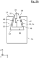
- In den in
Fig. 8A und8B gezeigten Ausführungsformen besteht die Dichtung 32 aus zwei in radialer Richtung R nebeneinander angeordneten Teilen. Die Dichtung 32 kann aber auch aus zwei in axialer Richtung Z übereinander angeordneten Teilen bestehen (nicht gezeigt). Dies ermöglicht ein einfaches Einbringen bzw. Montieren der Dichtung 32 in die Ausnehmung 30, da die Teile der Dichtung 32 nacheinander in die Ausnehmung 30 gesteckt werden können. - Damit die Teile der Dichtung 32 in montiertem Zustand nicht gegeneinander verrutschen oder sich ein Spalt zwischen den Teilen bildet, können die Teile der Dichtung 32 Verbindungsmittel 72 zum Verbinden der Teile aufweisen. In der in
Fig. 8A gezeigten Ausführungsform wirkt das Verbindungsmittel formschlüssig. Insbesondere umfassen die Verbindungsmittel 72 Nut und Feder 74, sodass beim Montieren der Dichtung 32 die beiden Teile durch Ineinanderdrücken verbunden werden können. Die formschlüssig wirkenden Verbindungsmittel 72 sind jedoch nicht auf Nut und Feder 74 beschränkt, sondern können beispielsweise auch ineinandergreifende Rippen und Rillen umfassen (nicht gezeigt). - In der in
Fig. 8B gezeigten Ausführungsform sind die beiden Teile der Dichtung nebeneinander in radialer Richtung R angeordnet und weisen jeweils einen Querschnitt in der Form eines gleichschenkligen Trapezes auf. Zwischen den Teilen ist ein Verbindungsmittel 72 in der Form eines Haftmittels 76 eingebracht, beispielsweise ein Harz oder ein Kleber, das beim Montieren der Dichtung 32 auf eines oder beide der Teile aufgebracht wird. Auf das Haftmittel 76 kann jedoch auch verzichtet werden, sodass die Teile reibschlüssig zusammenwirken. - In der in
Fig. 9 gezeigten Ausführungsform weist die Dichtung 32 an ihrer Unterseite 31 Einschnitte 78 auf, die sich von der Unterseite 31 schräg in die Dichtung 32 hinein erstrecken. Die Einschnitte 78 sind entlang der Längsrichtung L angeordnet und weisen einen Neigungswinkel 80 von kleiner als 90°, bevorzugt zwischen 10° und 70°, auf. Durch die Einschnitte oder Schnitte 78 werden Öffnungen und Lippen oder Laschen 82 gebildet, die in Richtung der Hochdruckseite, d.h. in Richtung des Auslasses 36 ausgerichtet oder offen sind. Die durch die Einschnitte 78 gebildeten Laschen 82 verhindern eine Rückströmung zwischen der Unterseite 31 der Dichtung und dem Boden 64 der Ausnehmung 30 in Längsrichtung L der Ausnehmung 30. Außerdem können die Laschen 82 bei geeigneter Ausgestaltung der Einschnitte 78 - zusätzlich oder alternativ zu dem Vorspannmittel 66 (sieheFig. 6 ) - eine elastische Anpresskraft bereitstellen. - Es versteht sich, dass die Schnitte 78 in beliebigen Seiten 31, 33, 46, 48 der Dichtung 32 eingebracht werden.
- In der in
Fig. 10 dargestellten Ausführungsform ist ein die erste Innenwand 42 aufweisender Teil der Wand 14 länger als ein die zweite Innenwand 44 aufweisender Teil der Wand 14. In anderen Worten unterscheidet sich die inFig. 10 gezeigte Ausnehmung 30 von den inFig. 3-8B gezeigten dadurch, dass sie eine größere Öffnung 58 aufweist. Dies ermöglicht ein einfaches Einkippen oder Eindrehen der Dichtung 32 in die Ausnehmung. - In der in
Fig. 11 dargestellten Ausführungsform sind die die Innenwände 42, 44 aufweisenden Abschnitte der Wand 14 plastisch verformbar ausgestaltet und bilden zunächst eine sich in der Längsrichtung L der Wände 14, 22 erstreckende Nut mit parallel zu der axialen Richtung Z verlaufenden Innenwänden 42, 44. Bei der Montage der Dichtung 32 wird zuerst die Dichtung 32 in die Nut eingesetzt (vgl. gestrichelter gerader Pfeil). Da die Öffnung der Nut breiter als die maximale horizontale Ausdehnung 54 der Dichtung 32 ist, kann die Dichtung 32 einfach in die Nut geschoben bzw. gesteckt werden (Montageschritt (a)). Danach werden die beiden Abschnitte der Wand 14 nach innen gebogen, sodass eine erfindungsgemäße Ausnehmung 30 gebildet wird, in der die Dichtung 32 eingefasst ist (vgl. gestrichelte und gebogene Pfeile, Montageschritt (b)). Das Umbiegen der Wandabschnitte erfolgt bevorzugt mittels eines Bördelwerkzeugs. Die Wandabschnitte können über die gesamte Länge des Spiralelements 12, 20 oder lediglich abschnittsweise in regel- oder unregelmäßigen Abständen umgebogen werden. Alternativ kann auch nur einer der Abschnitte der Wand 14 plastisch verformbar sein, während der gegenüberliegende Teil eine schräge Innenwand 44 oder gerade Innenwand 44 (sieheFig. 5 ) aufweist, sodass bei der Montage der Dichtung 32 nur ein Abschnitt auf einer Seite der Wand 14 umgebogen werden muss. - Es versteht sich, dass sowohl das erste Spiralelement 12 als auch das zweite Spiralelement 20 der Pumpstufe 11 erfindungsgemäß ausgestaltet sein kann. Insbesondere können, wie in
Fig. 12 gezeigt ist, die erste freie Stirnseite 18 der ersten Wand 14 und die zweite freie Stirnseite 26 der zweiten Wand 22 jeweils eine sich in Längsrichtung L der Wand erstreckende Ausnehmung 30a, 30b aufweisen, in der jeweils zumindest eine erfindungsgemäße Dichtung 32a, 32b beweglich angeordnet ist. - Grundsätzlich ist es denkbar, dass die Dichtung an ihrer Oberseite, die mit dem gegenüberliegenden Träger bei Betrieb der Pumpe zusammenwirkt, mit einem Material versehen oder bedeckt ist, das weicher ist, als das Material des Grundkörpers der Dichtung. Das weichere Material schleift sich bei dem Einlauf- oder Einschleifprozess der Dichtung schnell ein, so dass dieser Prozess beschleunigt wird. Beispielsweise ist das weichere Material pastös. Beide Materialien können elastisch sein.
- Zudem versteht es sich, dass Merkmale, die in Bezug auf bestimmte Ausführungsbeispiele der Erfindung beschrieben wurden, mit denen anderer Ausführungsbeispiele kombiniert werden können.
-
- 10
- Vakuumpumpe
- 11
- Scrollpumpstufe
- 12
- erstes Spiralelement
- 14
- erste Wand
- 16
- erster Träger
- 17
- Oberfläche des ersten Trägers
- 18
- erste freie Stirnseite
- 20
- zweites Spiralelement
- 22
- zweite Wand
- 24
- zweiter Träger
- 25
- Oberfläche des zweiten Trägers
- 26
- zweite freie Stirnseite
- 28, 28a, 28b
- Förderraum
- 30
- Ausnehmung
- 30a
- Ausnehmung der ersten Wand
- 30b
- Ausnehmung der zweiten Wand
- 31
- Unterseite der Dichtung
- 32, 32a, 32b
- Dichtung
- 33, 33a, 33b
- Oberseite der Dichtung
- 34
- Einlass
- 35
- Exzenterwelle
- 36
- Auslass
- 37
- Welle
- 38
- Elektromotor
- 39
- Motor-Stator
- 40
- Pumpengehäuse
- 41
- Motor-Rotor
- 42
- erste Innenwand der Ausnehmung
- 44
- zweite Innenwand der Ausnehmung
- 46
- erste Seitenwand der Dichtung
- 48
- zweite Seitenwand der Dichtung
- 50, 50a, 50b
- Neigung der Innenwand
- 52, 52a, 52b
- Neigung der Seitenwand
- 54
- maximale horizontale Ausdehnung der Dichtung
- 56
- Breite der Öffnung der Ausnehmung
- 58
- Öffnung der Ausnehmung
- 60
- maximale axiale Ausdehnung der Dichtung
- 62
- Tiefe der Ausnehmung
- 64
- Boden der Ausnehmung
- 66
- Vorspannmittel
- 68
- Federn
- 70
- Vertiefungen
- 72
- Verbindungsmittel
- 74
- Nut und Feder
- 76
- Haftmittel
- 78
- Einschnitte in der Dichtung
- 80
- Neigungswinkel der Schnitte
- 82
- Lippe oder Lasche
- P1, P2
- Druck im Förderraum
- F
- auf die Dichtung wirkende Kraft im Pumpbetrieb
- Aw
- Wellenachse
- Ae
- Exzenterachse
- Z
- axiale Richtung
- R
- radiale Richtung
- L
- Längsrichtung
Claims (15)
- Vakuumpumpe (10), insbesondere Scrollvakuumpumpe, umfassendein erstes Spiralelement (12), das eine spiralförmig um eine erste Achse verlaufende erste Wand (14) aufweist, die sich in einer axialen Richtung (Z) von einem ersten Träger (16) erstreckt und die eine dem ersten Träger (16) abgewandte erste freie Stirnseite (18) aufweist,ein zweites Spiralelement (20), das eine spiralförmig um eine zweite Achse verlaufende zweite Wand (22) aufweist, die sich in der axialen Richtung (Z) von einem zweiten Träger (24) erstreckt und die eine dem zweiten Träger (24) abgewandte zweite freie Stirnseite (26) aufweist,wobei das erste Spiralelement (12) und das zweite Spiralelement (20) relativ zueinander bewegbar sind und derart angeordnet sind, dass die erste Wand (14) und die zweite Wand (22) unter Ausbildung von Förderräumen (28) dichtend ineinandergreifen,wobei die freie Stirnseite (18, 26) zumindest einer der Wände (14, 22) eine sich in einer Längsrichtung (L) der Wand erstreckende Ausnehmung (30), insbesondere Nut, aufweist, in der zumindest eine Dichtung (32) beweglich angeordnet ist, undwobei die Ausnehmung (30) seitlich von zumindest einer Innenwand (42, 44) begrenzt ist, die zumindest abschnittsweise, bevorzugt durchgehend schräg zu der axialen Richtung (Z) verläuft und die dazu ausgebildet ist, mit einer zumindest abschnittsweise, bevorzugt durchgehend schräg zu der axialen Richtung (Z) verlaufenden Seitenwand (46, 48) der Dichtung (30) zusammenzuwirken.
- Vakuumpumpe (10) nach Anspruch 1,wobei die Ausnehmung (30) seitlich von einer ersten Innenwand (42) und einer zweiten Innenwand (44) begrenzt ist,wobei die erste Innenwand (42) und die zweite Innenwand (44) zumindest abschnittsweise, bevorzugt durchgehend schräg zu der axialen Richtung (Z) verlaufen, und/oder wobei die Dichtung (32) eine erste und eine zweite Seitenwand (46, 48) aufweist, die zumindest abschnittsweise, bevorzugt durchgehend schräg zu der axialen Richtung (Z) verlaufen.
- Vakuumpumpe (10) nach Anspruch 1 oder 2,
wobei die erste freie Stirnseite (18) der ersten Wand (14) und die zweite freie Stirnseite (26) der zweiten Wand (22) jeweils eine sich in Längsrichtung (L) der Wand erstreckende Ausnehmung (30a, 30b), insbesondere Nut, aufweisen, in der jeweils zumindest eine Dichtung (32a, 32b) beweglich angeordnet ist, wobei zumindest eine Innenwand der jeweiligen Ausnehmung schräg zu der entsprechenden axialen Richtung verläuft und die Innenwand dazu ausgebildet ist, mit einer schräg zu der axialen Richtung (Z) verlaufenden Seitenwand der entsprechenden Dichtung zusammenzuwirken. - Vakuumpumpe (10) nach einem der vorstehenden Ansprüche,
wobei eine Neigung (50) der Innenwand (42, 44) zu der axialen Richtung (Z) in der Längsrichtung (L) variiert und/oder wobei eine Neigung (52) der Seitenwand (46, 48) zu der axialen Richtung (Z) in der Längsrichtung (L) variiert. - Vakuumpumpe (10) nach einem der vorstehenden Ansprüche,
wobei eine Neigung (50) der Innenwand (42, 44) zu der axialen Richtung (Z) in der axialen Richtung (Z) variiert und/oder wobei eine Neigung (52) der Seitenwand (46, 48) zu der axialen Richtung (Z) in der axialen Richtung (Z) variiert. - Vakuumpumpe (10) nach Anspruch 4 oder 5,
wobei die Neigung (50) der Innenwand (42, 44) der Ausnehmung (30) im Wesentlichen der Neigung (52) der Seitenwand (46, 48) der Dichtung (32) entspricht. - Vakuumpumpe (10) nach einem der vorstehenden Ansprüche,
wobei eine maximale horizontale Ausdehnung (54) der Dichtung (32) größer als eine Breite (56) der Öffnung (58) der Ausnehmung (30) ist und/oder eine maximale axiale Ausdehnung (60) der Dichtung (32) größer als eine Tiefe (62) der Ausnehmung ist. - Vakuumpumpe (10) nach einem der vorstehenden Ansprüche,
wobei zwischen einer Unterseite (31) der Dichtung (32) und einem Boden (64) der Ausnehmung (30) zumindest ein elastisches Vorspannmittel (66) zum Vorspannen der Dichtung (32) in einer Richtung von dem Boden (64) der Ausnehmung (30) zu der Öffnung (58) der Ausnehmung (32) angeordnet ist. - Vakuumpumpe (10) nach einem der vorstehenden Ansprüche,
wobei zumindest eine bei Betrieb der Vakuumpumpe (10) mit der Dichtung (32) zusammenwirkende Innenwand (42) der Ausnehmung (30) zumindest abschnittsweise strukturiert ist, insbesondere Vertiefungen (70) und/oder Erhebungen aufweist. - Vakuumpumpe (10) nach einem der vorstehenden Ansprüche,
wobei die Dichtung (32) einen trapezförmigen Querschnitt, insbesondere einen Querschnitt in der Form eines gleichschenkligen Trapezes, aufweist. - Vakuumpumpe (10) nach einem der vorstehenden Ansprüche,
wobei die Dichtung (32) zwei- oder mehrteilig ausgebildet ist, insbesondere wobei die Dichtung in der Längsrichtung (L) und/oder in einer radialen Richtung (R) zwei- oder mehrteilig ausgebildet ist. - Vakuumpumpe (10) nach Anspruch 11,
wobei die Teile der Dichtung (32) Verbindungsmittel (72) zum Verbinden der Teile aufweisen, insbesondere wobei die Verbindungsmittel (72) formschlüssig wirken, bevorzugt wobei die Verbindungsmittel (72) Nut und Feder (74) umfassen. - Vakuumpumpe (10) nach Anspruch 2,
wobei ein die erste Innenwand (42) aufweisender Teil der Wand (14) länger als ein die zweite Innenwand (44) aufweisender Teil der Wand (14) ist. - Vakuumpumpe (10) nach einem der vorstehenden Ansprüche,
wobei ein die schräg verlaufende Innenwand (42, 44) aufweisender Teil der Wand (14) plastisch umgebogen ist. - Verfahren zum Herstellen eines Spiralelements für eine Vakuumpumpe (10) gemäß Anspruch 14, das Verfahren umfassend:- Bereitstellen eines Spiralelements (12, 20), das eine spiralförmig um eine zweite Achse verlaufende Wand (14, 22) aufweist, die sich in der axialen Richtung (Z) von einem Träger (16, 24) erstreckt und die eine dem Träger (16, 24) abgewandte freie Stirnseite (18, 26) aufweist,
wobei die freie Stirnseite (18, 26) eine sich in einer Längsrichtung (L) der Wand erstreckende Ausnehmung (30), insbesondere Nut, aufweist, wobei die Ausnehmung (30) seitlich von zumindest einer Innenwand (42, 44) begrenzt ist, die an einem der freien Stirnseite (18, 26) zugeordneten Abschnitt der Wand (14, 22) ausgebildet ist, der sich im Wesentlichen parallel zu der axialen Richtung (Z) erstreckt,- Einsetzen (a) einer Dichtung (32) in die Ausnehmung (30), und- zumindest abschnittsweises plastisches Umbiegen (b) des Abschnitts der Wand (14, 22), insbesondere mittels eines Bördelwerkzeugs, sodass die Innenwand (42, 44) zumindest abschnittsweise, bevorzugt durchgehend schräg zu der axialen Richtung (Z) verläuft.
Priority Applications (2)
| Application Number | Priority Date | Filing Date | Title |
|---|---|---|---|
| EP22216217.4A EP4174285B1 (de) | 2022-12-22 | 2022-12-22 | Spiralvakuumpumpe |
| US18/545,789 US12221961B2 (en) | 2022-12-22 | 2023-12-19 | Vacuum pump with movable trapezoidal seal |
Applications Claiming Priority (1)
| Application Number | Priority Date | Filing Date | Title |
|---|---|---|---|
| EP22216217.4A EP4174285B1 (de) | 2022-12-22 | 2022-12-22 | Spiralvakuumpumpe |
Publications (2)
| Publication Number | Publication Date |
|---|---|
| EP4174285A1 true EP4174285A1 (de) | 2023-05-03 |
| EP4174285B1 EP4174285B1 (de) | 2024-10-23 |
Family
ID=84569342
Family Applications (1)
| Application Number | Title | Priority Date | Filing Date |
|---|---|---|---|
| EP22216217.4A Active EP4174285B1 (de) | 2022-12-22 | 2022-12-22 | Spiralvakuumpumpe |
Country Status (2)
| Country | Link |
|---|---|
| US (1) | US12221961B2 (de) |
| EP (1) | EP4174285B1 (de) |
Cited By (3)
| Publication number | Priority date | Publication date | Assignee | Title |
|---|---|---|---|---|
| EP4407183A1 (de) | 2024-05-31 | 2024-07-31 | Pfeiffer Vacuum Technology AG | Scrollvakuumpumpe und ihr betriebsverfahren |
| EP4467810A2 (de) | 2024-07-15 | 2024-11-27 | Pfeiffer Vacuum Technology AG | Scrollvakuumpumpe und verfahren zum herstellen einer scrollvakuumpumpe |
| EP4636251A2 (de) | 2025-09-09 | 2025-10-22 | Pfeiffer Vacuum Technology AG | Scrollvakuumpumpe |
Citations (8)
| Publication number | Priority date | Publication date | Assignee | Title |
|---|---|---|---|---|
| US4462771A (en) * | 1981-02-09 | 1984-07-31 | The Trane Company | Wrap element and tip seal for use in fluid apparatus of the scroll type and method for making same |
| US4730375A (en) * | 1984-05-18 | 1988-03-15 | Mitsubishi Denki Kabushiki Kaisha | Method for the assembly of a scroll-type apparatus |
| US4732550A (en) * | 1985-11-27 | 1988-03-22 | Mitsubishi Denki Kabushiki Kaisha | Scroll fluid machine with fine regulation elements in grooves having stepped portion |
| JPH06272679A (ja) * | 1993-03-17 | 1994-09-27 | Tokico Ltd | スクロール式流体機械 |
| JPH08232858A (ja) * | 1995-02-27 | 1996-09-10 | Mitsubishi Electric Corp | スクロール圧縮機 |
| JP2007162622A (ja) * | 2005-12-15 | 2007-06-28 | Sanden Corp | スクロール型流体機械 |
| US20160327042A1 (en) * | 2006-02-14 | 2016-11-10 | Robert W. Shaffer | Multi stage scroll vacuum pumps and related scroll devices |
| EP3153706B1 (de) | 2015-10-06 | 2020-06-17 | Pfeiffer Vacuum Gmbh | Pumpe |
Family Cites Families (6)
| Publication number | Priority date | Publication date | Assignee | Title |
|---|---|---|---|---|
| AU547490B2 (en) * | 1980-05-31 | 1985-10-24 | Sanden Corporation | Scroll-type pump |
| JPH06330872A (ja) * | 1993-05-21 | 1994-11-29 | Daikin Ind Ltd | スクロール流体機械 |
| JP3422747B2 (ja) | 2000-03-06 | 2003-06-30 | アネスト岩田株式会社 | スクロール流体機械 |
| GB0914230D0 (en) * | 2009-08-14 | 2009-09-30 | Edwards Ltd | Scroll pump |
| JP5352384B2 (ja) | 2009-08-31 | 2013-11-27 | 株式会社日立産機システム | スクロール式流体機械 |
| JP7220692B2 (ja) | 2019-10-07 | 2023-02-10 | プファイファー・ヴァキューム・ゲーエムベーハー | 真空ポンプ、スクロールポンプ及びその製造方法 |
-
2022
- 2022-12-22 EP EP22216217.4A patent/EP4174285B1/de active Active
-
2023
- 2023-12-19 US US18/545,789 patent/US12221961B2/en active Active
Patent Citations (8)
| Publication number | Priority date | Publication date | Assignee | Title |
|---|---|---|---|---|
| US4462771A (en) * | 1981-02-09 | 1984-07-31 | The Trane Company | Wrap element and tip seal for use in fluid apparatus of the scroll type and method for making same |
| US4730375A (en) * | 1984-05-18 | 1988-03-15 | Mitsubishi Denki Kabushiki Kaisha | Method for the assembly of a scroll-type apparatus |
| US4732550A (en) * | 1985-11-27 | 1988-03-22 | Mitsubishi Denki Kabushiki Kaisha | Scroll fluid machine with fine regulation elements in grooves having stepped portion |
| JPH06272679A (ja) * | 1993-03-17 | 1994-09-27 | Tokico Ltd | スクロール式流体機械 |
| JPH08232858A (ja) * | 1995-02-27 | 1996-09-10 | Mitsubishi Electric Corp | スクロール圧縮機 |
| JP2007162622A (ja) * | 2005-12-15 | 2007-06-28 | Sanden Corp | スクロール型流体機械 |
| US20160327042A1 (en) * | 2006-02-14 | 2016-11-10 | Robert W. Shaffer | Multi stage scroll vacuum pumps and related scroll devices |
| EP3153706B1 (de) | 2015-10-06 | 2020-06-17 | Pfeiffer Vacuum Gmbh | Pumpe |
Cited By (3)
| Publication number | Priority date | Publication date | Assignee | Title |
|---|---|---|---|---|
| EP4407183A1 (de) | 2024-05-31 | 2024-07-31 | Pfeiffer Vacuum Technology AG | Scrollvakuumpumpe und ihr betriebsverfahren |
| EP4467810A2 (de) | 2024-07-15 | 2024-11-27 | Pfeiffer Vacuum Technology AG | Scrollvakuumpumpe und verfahren zum herstellen einer scrollvakuumpumpe |
| EP4636251A2 (de) | 2025-09-09 | 2025-10-22 | Pfeiffer Vacuum Technology AG | Scrollvakuumpumpe |
Also Published As
| Publication number | Publication date |
|---|---|
| US12221961B2 (en) | 2025-02-11 |
| EP4174285B1 (de) | 2024-10-23 |
| US20240209855A1 (en) | 2024-06-27 |
Similar Documents
| Publication | Publication Date | Title |
|---|---|---|
| EP4174285B1 (de) | Spiralvakuumpumpe | |
| EP1448894B1 (de) | Selbstansaugende hybridpumpe | |
| DE102007039628B4 (de) | Spiralverdichter | |
| EP3014149B1 (de) | Radialwellendichtung | |
| DE3638368A1 (de) | Spiral-fluidmaschine | |
| EP1350995A2 (de) | Dichtring | |
| DE69002885T2 (de) | Spiralverdrängungsanlage für Fluide. | |
| DE60209406T2 (de) | Rohrpumpe | |
| DE102014107735B4 (de) | Flügel mit axialer Abdichtung | |
| EP3153706A1 (de) | Pumpe | |
| WO2017158003A1 (de) | Kreiselpumpe mit einer anordnung zur reduzierung einer rückströmung | |
| DE102019200507A1 (de) | Scrollverdichter für eine Fahrzeugklimaanlage | |
| EP3230592B1 (de) | Gerotorpumpe | |
| DE4313442A1 (de) | Fluidpumpe | |
| EP0415089B1 (de) | Axialdichtung | |
| DE202022107205U1 (de) | Exzenterschneckenpumpe mit gekapselter Statorauskleidung | |
| DE102008042233A1 (de) | Exzenterschneckenpumpe sowie mechanisches Koppelelement für die Exzenterschnecke einer Exzenterschneckenpumpe | |
| EP3339654B1 (de) | Kreiselpumpe | |
| DE102006016790B3 (de) | Zellenpumpe | |
| DE102016108640A1 (de) | Schraubenspindelpumpe mit beweglichem Gehäuseeinsatz | |
| DE102006016806A1 (de) | Verdrängermaschine | |
| DE102020129864B4 (de) | Vorrichtung zum Verdichten eines gasförmigen Fluids | |
| WO2016139230A1 (de) | Rotationskolbenpumpe | |
| DE102013204504C5 (de) | Flügelzellenpumpe mit verbesserter Leistung | |
| DE3521253A1 (de) | Spiralverdichter |
Legal Events
| Date | Code | Title | Description |
|---|---|---|---|
| PUAI | Public reference made under article 153(3) epc to a published international application that has entered the european phase |
Free format text: ORIGINAL CODE: 0009012 |
|
| STAA | Information on the status of an ep patent application or granted ep patent |
Free format text: STATUS: THE APPLICATION HAS BEEN PUBLISHED |
|
| AK | Designated contracting states |
Kind code of ref document: A1 Designated state(s): AL AT BE BG CH CY CZ DE DK EE ES FI FR GB GR HR HU IE IS IT LI LT LU LV MC ME MK MT NL NO PL PT RO RS SE SI SK SM TR |
|
| STAA | Information on the status of an ep patent application or granted ep patent |
Free format text: STATUS: REQUEST FOR EXAMINATION WAS MADE |
|
| 17P | Request for examination filed |
Effective date: 20231011 |
|
| RBV | Designated contracting states (corrected) |
Designated state(s): AL AT BE BG CH CY CZ DE DK EE ES FI FR GB GR HR HU IE IS IT LI LT LU LV MC ME MK MT NL NO PL PT RO RS SE SI SK SM TR |
|
| STAA | Information on the status of an ep patent application or granted ep patent |
Free format text: STATUS: EXAMINATION IS IN PROGRESS |
|
| 17Q | First examination report despatched |
Effective date: 20240103 |
|
| GRAP | Despatch of communication of intention to grant a patent |
Free format text: ORIGINAL CODE: EPIDOSNIGR1 |
|
| STAA | Information on the status of an ep patent application or granted ep patent |
Free format text: STATUS: GRANT OF PATENT IS INTENDED |
|
| INTG | Intention to grant announced |
Effective date: 20240801 |
|
| GRAS | Grant fee paid |
Free format text: ORIGINAL CODE: EPIDOSNIGR3 |
|
| GRAA | (expected) grant |
Free format text: ORIGINAL CODE: 0009210 |
|
| STAA | Information on the status of an ep patent application or granted ep patent |
Free format text: STATUS: THE PATENT HAS BEEN GRANTED |
|
| AK | Designated contracting states |
Kind code of ref document: B1 Designated state(s): AL AT BE BG CH CY CZ DE DK EE ES FI FR GB GR HR HU IE IS IT LI LT LU LV MC ME MK MT NL NO PL PT RO RS SE SI SK SM TR |
|
| REG | Reference to a national code |
Ref country code: GB Ref legal event code: FG4D Free format text: NOT ENGLISH |
|
| REG | Reference to a national code |
Ref country code: CH Ref legal event code: EP |
|
| REG | Reference to a national code |
Ref country code: DE Ref legal event code: R096 Ref document number: 502022001963 Country of ref document: DE |
|
| REG | Reference to a national code |
Ref country code: IE Ref legal event code: FG4D Free format text: LANGUAGE OF EP DOCUMENT: GERMAN |
|
| REG | Reference to a national code |
Ref country code: LT Ref legal event code: MG9D |
|
| REG | Reference to a national code |
Ref country code: NL Ref legal event code: MP Effective date: 20241023 |
|
| PG25 | Lapsed in a contracting state [announced via postgrant information from national office to epo] |
Ref country code: NL Free format text: LAPSE BECAUSE OF FAILURE TO SUBMIT A TRANSLATION OF THE DESCRIPTION OR TO PAY THE FEE WITHIN THE PRESCRIBED TIME-LIMIT Effective date: 20241023 |
|
| PG25 | Lapsed in a contracting state [announced via postgrant information from national office to epo] |
Ref country code: NL Free format text: LAPSE BECAUSE OF FAILURE TO SUBMIT A TRANSLATION OF THE DESCRIPTION OR TO PAY THE FEE WITHIN THE PRESCRIBED TIME-LIMIT Effective date: 20241023 |
|
| PG25 | Lapsed in a contracting state [announced via postgrant information from national office to epo] |
Ref country code: IS Free format text: LAPSE BECAUSE OF FAILURE TO SUBMIT A TRANSLATION OF THE DESCRIPTION OR TO PAY THE FEE WITHIN THE PRESCRIBED TIME-LIMIT Effective date: 20250223 Ref country code: PT Free format text: LAPSE BECAUSE OF FAILURE TO SUBMIT A TRANSLATION OF THE DESCRIPTION OR TO PAY THE FEE WITHIN THE PRESCRIBED TIME-LIMIT Effective date: 20250224 Ref country code: HR Free format text: LAPSE BECAUSE OF FAILURE TO SUBMIT A TRANSLATION OF THE DESCRIPTION OR TO PAY THE FEE WITHIN THE PRESCRIBED TIME-LIMIT Effective date: 20241023 |
|
| PG25 | Lapsed in a contracting state [announced via postgrant information from national office to epo] |
Ref country code: FI Free format text: LAPSE BECAUSE OF FAILURE TO SUBMIT A TRANSLATION OF THE DESCRIPTION OR TO PAY THE FEE WITHIN THE PRESCRIBED TIME-LIMIT Effective date: 20241023 |
|
| PG25 | Lapsed in a contracting state [announced via postgrant information from national office to epo] |
Ref country code: BG Free format text: LAPSE BECAUSE OF FAILURE TO SUBMIT A TRANSLATION OF THE DESCRIPTION OR TO PAY THE FEE WITHIN THE PRESCRIBED TIME-LIMIT Effective date: 20241023 |
|
| PG25 | Lapsed in a contracting state [announced via postgrant information from national office to epo] |
Ref country code: ES Free format text: LAPSE BECAUSE OF FAILURE TO SUBMIT A TRANSLATION OF THE DESCRIPTION OR TO PAY THE FEE WITHIN THE PRESCRIBED TIME-LIMIT Effective date: 20241023 |
|
| PG25 | Lapsed in a contracting state [announced via postgrant information from national office to epo] |
Ref country code: NO Free format text: LAPSE BECAUSE OF FAILURE TO SUBMIT A TRANSLATION OF THE DESCRIPTION OR TO PAY THE FEE WITHIN THE PRESCRIBED TIME-LIMIT Effective date: 20250123 |
|
| PG25 | Lapsed in a contracting state [announced via postgrant information from national office to epo] |
Ref country code: GR Free format text: LAPSE BECAUSE OF FAILURE TO SUBMIT A TRANSLATION OF THE DESCRIPTION OR TO PAY THE FEE WITHIN THE PRESCRIBED TIME-LIMIT Effective date: 20250124 Ref country code: LV Free format text: LAPSE BECAUSE OF FAILURE TO SUBMIT A TRANSLATION OF THE DESCRIPTION OR TO PAY THE FEE WITHIN THE PRESCRIBED TIME-LIMIT Effective date: 20241023 |
|
| PG25 | Lapsed in a contracting state [announced via postgrant information from national office to epo] |
Ref country code: PL Free format text: LAPSE BECAUSE OF FAILURE TO SUBMIT A TRANSLATION OF THE DESCRIPTION OR TO PAY THE FEE WITHIN THE PRESCRIBED TIME-LIMIT Effective date: 20241023 |
|
| PG25 | Lapsed in a contracting state [announced via postgrant information from national office to epo] |
Ref country code: RS Free format text: LAPSE BECAUSE OF FAILURE TO SUBMIT A TRANSLATION OF THE DESCRIPTION OR TO PAY THE FEE WITHIN THE PRESCRIBED TIME-LIMIT Effective date: 20250123 |
|
| PG25 | Lapsed in a contracting state [announced via postgrant information from national office to epo] |
Ref country code: SM Free format text: LAPSE BECAUSE OF FAILURE TO SUBMIT A TRANSLATION OF THE DESCRIPTION OR TO PAY THE FEE WITHIN THE PRESCRIBED TIME-LIMIT Effective date: 20241023 |
|
| PG25 | Lapsed in a contracting state [announced via postgrant information from national office to epo] |
Ref country code: MC Free format text: LAPSE BECAUSE OF FAILURE TO SUBMIT A TRANSLATION OF THE DESCRIPTION OR TO PAY THE FEE WITHIN THE PRESCRIBED TIME-LIMIT Effective date: 20241023 |
|
| PG25 | Lapsed in a contracting state [announced via postgrant information from national office to epo] |
Ref country code: DK Free format text: LAPSE BECAUSE OF FAILURE TO SUBMIT A TRANSLATION OF THE DESCRIPTION OR TO PAY THE FEE WITHIN THE PRESCRIBED TIME-LIMIT Effective date: 20241023 |
|
| PG25 | Lapsed in a contracting state [announced via postgrant information from national office to epo] |
Ref country code: EE Free format text: LAPSE BECAUSE OF FAILURE TO SUBMIT A TRANSLATION OF THE DESCRIPTION OR TO PAY THE FEE WITHIN THE PRESCRIBED TIME-LIMIT Effective date: 20241023 |
|
| PG25 | Lapsed in a contracting state [announced via postgrant information from national office to epo] |
Ref country code: RO Free format text: LAPSE BECAUSE OF FAILURE TO SUBMIT A TRANSLATION OF THE DESCRIPTION OR TO PAY THE FEE WITHIN THE PRESCRIBED TIME-LIMIT Effective date: 20241023 |
|
| REG | Reference to a national code |
Ref country code: DE Ref legal event code: R097 Ref document number: 502022001963 Country of ref document: DE |
|
| PG25 | Lapsed in a contracting state [announced via postgrant information from national office to epo] |
Ref country code: SK Free format text: LAPSE BECAUSE OF FAILURE TO SUBMIT A TRANSLATION OF THE DESCRIPTION OR TO PAY THE FEE WITHIN THE PRESCRIBED TIME-LIMIT Effective date: 20241023 |
|
| PG25 | Lapsed in a contracting state [announced via postgrant information from national office to epo] |
Ref country code: LU Free format text: LAPSE BECAUSE OF NON-PAYMENT OF DUE FEES Effective date: 20241222 |
|
| PLBE | No opposition filed within time limit |
Free format text: ORIGINAL CODE: 0009261 |
|
| STAA | Information on the status of an ep patent application or granted ep patent |
Free format text: STATUS: NO OPPOSITION FILED WITHIN TIME LIMIT |
|
| PG25 | Lapsed in a contracting state [announced via postgrant information from national office to epo] |
Ref country code: SE Free format text: LAPSE BECAUSE OF FAILURE TO SUBMIT A TRANSLATION OF THE DESCRIPTION OR TO PAY THE FEE WITHIN THE PRESCRIBED TIME-LIMIT Effective date: 20241023 |
|
| 26N | No opposition filed |
Effective date: 20250724 |
|
| REG | Reference to a national code |
Ref country code: BE Ref legal event code: MM Effective date: 20241231 |
|
| PG25 | Lapsed in a contracting state [announced via postgrant information from national office to epo] |
Ref country code: BE Free format text: LAPSE BECAUSE OF NON-PAYMENT OF DUE FEES Effective date: 20241231 |
|
| PG25 | Lapsed in a contracting state [announced via postgrant information from national office to epo] |
Ref country code: FR Free format text: LAPSE BECAUSE OF NON-PAYMENT OF DUE FEES Effective date: 20241223 |
|
| PG25 | Lapsed in a contracting state [announced via postgrant information from national office to epo] |
Ref country code: IE Free format text: LAPSE BECAUSE OF NON-PAYMENT OF DUE FEES Effective date: 20241222 |
|
| PGFP | Annual fee paid to national office [announced via postgrant information from national office to epo] |
Ref country code: AT Payment date: 20260113 Year of fee payment: 4 |
|
| PGFP | Annual fee paid to national office [announced via postgrant information from national office to epo] |
Ref country code: CZ Payment date: 20251218 Year of fee payment: 4 |
|
| PGFP | Annual fee paid to national office [announced via postgrant information from national office to epo] |
Ref country code: DE Payment date: 20260224 Year of fee payment: 4 |
|
| PGFP | Annual fee paid to national office [announced via postgrant information from national office to epo] |
Ref country code: IT Payment date: 20251231 Year of fee payment: 4 |