EP4183447B1 - Procédé de conception d`un filtre à nervure dans un système de traitement pbs - Google Patents
Procédé de conception d`un filtre à nervure dans un système de traitement pbs Download PDFInfo
- Publication number
- EP4183447B1 EP4183447B1 EP21208699.5A EP21208699A EP4183447B1 EP 4183447 B1 EP4183447 B1 EP 4183447B1 EP 21208699 A EP21208699 A EP 21208699A EP 4183447 B1 EP4183447 B1 EP 4183447B1
- Authority
- EP
- European Patent Office
- Prior art keywords
- degrading
- subunit
- subunits
- energy
- unit
- Prior art date
- Legal status (The legal status is an assumption and is not a legal conclusion. Google has not performed a legal analysis and makes no representation as to the accuracy of the status listed.)
- Active
Links
Images




Classifications
-
- A—HUMAN NECESSITIES
- A61—MEDICAL OR VETERINARY SCIENCE; HYGIENE
- A61N—ELECTROTHERAPY; MAGNETOTHERAPY; RADIATION THERAPY; ULTRASOUND THERAPY
- A61N5/00—Radiation therapy
- A61N5/10—X-ray therapy; Gamma-ray therapy; Particle-irradiation therapy
- A61N5/1042—X-ray therapy; Gamma-ray therapy; Particle-irradiation therapy with spatial modulation of the radiation beam within the treatment head
- A61N5/1043—Scanning the radiation beam, e.g. spot scanning or raster scanning
-
- A—HUMAN NECESSITIES
- A61—MEDICAL OR VETERINARY SCIENCE; HYGIENE
- A61N—ELECTROTHERAPY; MAGNETOTHERAPY; RADIATION THERAPY; ULTRASOUND THERAPY
- A61N5/00—Radiation therapy
- A61N5/10—X-ray therapy; Gamma-ray therapy; Particle-irradiation therapy
-
- A—HUMAN NECESSITIES
- A61—MEDICAL OR VETERINARY SCIENCE; HYGIENE
- A61N—ELECTROTHERAPY; MAGNETOTHERAPY; RADIATION THERAPY; ULTRASOUND THERAPY
- A61N5/00—Radiation therapy
- A61N5/10—X-ray therapy; Gamma-ray therapy; Particle-irradiation therapy
- A61N5/1001—X-ray therapy; Gamma-ray therapy; Particle-irradiation therapy using radiation sources introduced into or applied onto the body; brachytherapy
-
- A—HUMAN NECESSITIES
- A61—MEDICAL OR VETERINARY SCIENCE; HYGIENE
- A61N—ELECTROTHERAPY; MAGNETOTHERAPY; RADIATION THERAPY; ULTRASOUND THERAPY
- A61N5/00—Radiation therapy
- A61N5/10—X-ray therapy; Gamma-ray therapy; Particle-irradiation therapy
- A61N5/103—Treatment planning systems
-
- A—HUMAN NECESSITIES
- A61—MEDICAL OR VETERINARY SCIENCE; HYGIENE
- A61N—ELECTROTHERAPY; MAGNETOTHERAPY; RADIATION THERAPY; ULTRASOUND THERAPY
- A61N5/00—Radiation therapy
- A61N5/10—X-ray therapy; Gamma-ray therapy; Particle-irradiation therapy
- A61N5/103—Treatment planning systems
- A61N5/1039—Treatment planning systems using functional images, e.g. PET or MRI
-
- A—HUMAN NECESSITIES
- A61—MEDICAL OR VETERINARY SCIENCE; HYGIENE
- A61N—ELECTROTHERAPY; MAGNETOTHERAPY; RADIATION THERAPY; ULTRASOUND THERAPY
- A61N5/00—Radiation therapy
- A61N5/10—X-ray therapy; Gamma-ray therapy; Particle-irradiation therapy
- A61N5/1077—Beam delivery systems
-
- G—PHYSICS
- G21—NUCLEAR PHYSICS; NUCLEAR ENGINEERING
- G21K—HANDLING OF PARTICLES OR IONISING RADIATION NOT OTHERWISE PROVIDED FOR; IRRADIATION DEVICES; GAMMA RAY OR X-RAY MICROSCOPES
- G21K1/00—Arrangements for handling particles or ionising radiation, e.g. focusing or moderating
- G21K1/10—Scattering devices; Absorbing devices; Ionising radiation filters
-
- A—HUMAN NECESSITIES
- A61—MEDICAL OR VETERINARY SCIENCE; HYGIENE
- A61N—ELECTROTHERAPY; MAGNETOTHERAPY; RADIATION THERAPY; ULTRASOUND THERAPY
- A61N5/00—Radiation therapy
- A61N5/10—X-ray therapy; Gamma-ray therapy; Particle-irradiation therapy
- A61N2005/1085—X-ray therapy; Gamma-ray therapy; Particle-irradiation therapy characterised by the type of particles applied to the patient
- A61N2005/1087—Ions; Protons
-
- A—HUMAN NECESSITIES
- A61—MEDICAL OR VETERINARY SCIENCE; HYGIENE
- A61N—ELECTROTHERAPY; MAGNETOTHERAPY; RADIATION THERAPY; ULTRASOUND THERAPY
- A61N5/00—Radiation therapy
- A61N5/10—X-ray therapy; Gamma-ray therapy; Particle-irradiation therapy
- A61N2005/1092—Details
-
- A—HUMAN NECESSITIES
- A61—MEDICAL OR VETERINARY SCIENCE; HYGIENE
- A61N—ELECTROTHERAPY; MAGNETOTHERAPY; RADIATION THERAPY; ULTRASOUND THERAPY
- A61N5/00—Radiation therapy
- A61N5/10—X-ray therapy; Gamma-ray therapy; Particle-irradiation therapy
- A61N2005/1092—Details
- A61N2005/1095—Elements inserted into the radiation path within the system, e.g. filters or wedges
-
- A—HUMAN NECESSITIES
- A61—MEDICAL OR VETERINARY SCIENCE; HYGIENE
- A61N—ELECTROTHERAPY; MAGNETOTHERAPY; RADIATION THERAPY; ULTRASOUND THERAPY
- A61N5/00—Radiation therapy
- A61N5/10—X-ray therapy; Gamma-ray therapy; Particle-irradiation therapy
- A61N5/1042—X-ray therapy; Gamma-ray therapy; Particle-irradiation therapy with spatial modulation of the radiation beam within the treatment head
- A61N5/1045—X-ray therapy; Gamma-ray therapy; Particle-irradiation therapy with spatial modulation of the radiation beam within the treatment head using a multi-leaf collimator, e.g. for intensity modulated radiation therapy or IMRT
Definitions
- the present invention relates to a ridge filter for depositing predefined doses (Dij) over a whole treatment volume (V) by irradiation thereof by beams of accelerated particles (preferably protons) by pencil beam scanning (PBS) in a single painting layer.
- the present invention concerns a method for designing such ridge filter, optimizing the dimensions thereof to accurately deposit the doses (Dij) according to a pre-established treatment plan.
- the ridge filter of the present invention is particularly adapted for flash irradiation of the treatment volume (V) or of a portion thereof by PBS at ultra-high dose deposition rates (HDR).
- Radiotherapy with particles or waves such as electron beams, protons beams, heavy ions beams, x-rays, ⁇ -rays, and the like, has become an essential tool for treating patients with tumours.
- tumoural cells and healthy cells comprised in a volume are damaged by such radiations
- a first challenge in cancer treatment is to define a treatment plan ensuring that defined doses are deposited into the tumoural cells to effectively destroy or kill them, while limiting the doses deposition into healthy cells to spare them as much as possible.
- a second challenge is to actually deposit the defined doses into the tumoural cells whilst limited doses are actually deposited into the healthy cells, especially those adjacent to the tumoural cells
- the treatment plan must ensure that, at the end of the treatment, a total target dose sufficient to kill the tumoural cells is delivered into the volume, whilst minimizing the degradation of the healthy cells adjacent to the tumoural cells.
- Different radiations deposit their energies in different patterns. For example, X-rays deposit most of their energy near the level of the skin, and the deposited energy decreases with penetration depth into the tissues. Healthy tissues located upstream of a target volume of tumoural cells therefore receive a higher dose than the tumoural cells of the target volume.
- charged particle beams in particular protons deposit most of their energy close to the end of their beam path, forming a so-called Bragg peak.
- Pencil beam scanning is a technique consisting of steering a beam of charged particles along corresponding beam axes (Xi) towards individual spots of a mesh of spots (Sij) defining a target volume comprising tumoral cells. Predefined target doses are thus deposited into cells aligned with the individual spots. The beam is steered along the corresponding beam axes (Xi) and the dose deposition proceeds according to the treatment plan defining the doses (Dij) to be deposited into each cell aligned with a given spot along a beam axis (Xi), as well as the scanning sequence of spots irradiation.
- PBS reduces unnecessary radiation exposure to surrounding non-cancerous cells by shaping the area being treated to mirror the tumour geometry. Beside the geometry of the target, PBS allows local tuning of the intensity of a beam depending on the position of the spot within the target.
- Each painting layer defines a number of cells (Cij, C(i+1)j ...) defined as generalized cylinders with the corresponding spot (Sij) as a base and with generatrixes parallel to the corresponding beam axis (Xi).
- the cells (Cij) have the same thickness as the corresponding layer (Tj).
- the superposition of the painting layers (Tj) defines a whole of the treatment volume (V).
- the spots (Sij) of an upstream layer (Tj) are not necessarily aligned along a corresponding beam axis (Xi) with the corresponding spots (Si(j+1), Si(j+2) (7) of the downstream layers (T(j+1), T(j+2) ).
- upstream and downstream are defined relative to the charged particles beam (100.i) direction.
- generalized cylinder refer herein to a surface consisting of all the points on all the lines which are parallel to a generatrix and which pass through a perimeter of a base comprised in a plane not parallel to the generatrix.
- the base can have any planar geometry. In the special case where the base is circular, it defines a circular cylinder. In case the base is polygonal, it forms a prism.
- a right cylinder is a cylinder whose base is normal to the generatrix.
- PBS is very advantageous because it optimizes the geometrical distribution of the doses deposition to match it with the geometry of the treatment volume (V) enclosing the tumour.
- PBS can, however, be long as the beam must scan over each spot (Sij) and over each layer (Tj). Moving the beam from a beam axis (Xi) to a different beam axis (X(i+1)) requires a time of a few ms. Changing the energy of a given beam parallel to a given beam axis (Xi) to deposit the desired doses (Dij) into the cells (Cij) of different layers (Tj) is more time consuming and is of the order of 500 ms. The number of layers (Tj) therefore has a strong influence on the duration of a treatment..
- a given beam parallel to a given beam axis (Xi) can successively deposit a predefined charge into the corresponding cells (Cij) of each painting layer aligned along the given beam axis (Xi) by superimposing a number of Bragg peaks staggered in depth at each painting layer along the beam axis (Xi).
- SOBP Spread Out Bragg Peaks
- This operation requires successively changing the energy of the given beam such that the corresponding Bragg Peaks be centred on the corresponding cells (Cij). This operation is time consuming.
- the treatment plan comprises FLASH irradiation, wherein doses are deposited into the cells at ultra-high deposition rates (HDR), of at least 1 Gy / s.
- HDR ultra-high deposition rates
- a given dose deposited at HDR has shown to spare healthy cells relative to the same dose deposited at lower deposition rates (CDR).
- CDR lower deposition rates
- Depositing doses (Dij) layer by layer into a treatment volume (V) by PBS would, however, substantially reduce the deposition rates into the cells, since the cells located upstream in the volume (V) are necessarily repeatedly irradiated several times until all cells (Cij) aligned along the given beam axis (Xi) have received their corresponding doses (Dij).
- Depositing the predefined doses (Dij) into a treatment volume by PBS with a single layer can be achieved by using a ridge filter.
- a ridge filter requires the spots (Sij, Si(j+1) ...) of each layer (Tj) to be aligned along corresponding beam axes (Xi).
- Ridge filters comprising energy degrading units in the form of smooth- or step-pyramids or crests have been described in the art. For example, Simeonov et al., Phys. Med. Biol. 62 (2017) 7075 describe a ridge filter comprising a plurality of energy degrading units in the form of smooth pyramids extending along the beam axes (Xi) corresponding to each spot (Sij).
- Sakae et al., Med. Phys. 27, 2, (2000) 368 describe a multi-layered ridge filter, the layers being stacked on top of each other, and each layer comprising parallel linear crests having a step-pyramidal cross-section.
- JP2019136167 describes a ridge filter comprising conical or triangular pyramid protrusions positioned upstream of a Bragg peak expansion filter in the shape of a plate comprising a plurality of through-holes for increasing the width of the SOBP along the corresponding beam axis (Xi).
- a ridge filter The principle of a ridge filter is that portions of a beam (100.i) of given energy oriented along a corresponding beam axis (Xi) pass through different material thicknesses of the filter, producing Bragg peaks with different ranges, whose superposition results in a homogeneous SOBP extending over a cylindrical volume defined by a spot (Si1) in a first layer (T1) to a corresponding spot (SiN) in a last layer (TN) downstream of the first layer (T1) spanning a whole depth of the treatment volume (V) along the corresponding beam axis (Xi).
- the present invention concerns a method for designing a ridge filter of a treatment system comprising a charged particle accelerator, preferably an accelerator of protons, a beamline nozzle, a collimator, and the like, collectively herein referred to as an accelerator, for depositing with beams of accelerated particles specific doses (Dij) into specific locations within a treatment volume of tissue comprising tumoral cells.
- a charged particle accelerator preferably an accelerator of protons, a beamline nozzle, a collimator, and the like, collectively herein referred to as an accelerator
- the present invention concerns deposition by pencil beam scanning (PBS), spot by spot according to a predefined treatment plan (TP), in a single painting layer defining the whole treatment volume.
- PBS pencil beam scanning
- TP predefined treatment plan
- the beams extend along corresponding beam axes (Xi) substantially parallel to an irradiation axis (X), diverging from parallelism from the irradiation axis (X) by an angle comprised within ⁇ 5°, preferably within ⁇ 3°.
- the tissue is characterized by a maximum beam range (W0), defined as the water equivalent distance at which the beam stops propagating through the tissue.
- water equivalent thickness WET
- WET water equivalent thickness
- a shortest water equivalent thickness (d0) and longest water equivalent thickness (d1) to a skin of a patient are defined as the points of the boundary closest to and furthest away from the skin, respectively, measured along the irradiation axis (X).
- An array of subvolumes (Vi) is defined, each subvolume extending parallel to the corresponding beam axes (Xi) from the skin of the patient to the corresponding furthest water equivalent thickness, and whose projection onto a plane (Y,Z) normal to the irradiation axis (X) defines an array of spots covering a whole area of a projection of the volume onto the plane (Y,Z).
- a cell For each slice (Tj) of the N slices (T1-TN), comprised within a subvolume (Vi), a cell is defined as a portion of the subvolume (Vi) comprised within the corresponding slice (Tj), For each cell of the given subvolume (Vi), a cell water equivalent thickness is determined from the skin to a geometrical centre of the cells.
- a beam weight ( ⁇ ij) is attributed to each cell required for depositing into the cell the specific dose (Dij) according to the TP.
- the beam weight ( ⁇ ij) is proportional to the number of charged particles at the cell water equivalent thickness.
- the ridge filter can be designed with a set of energy degrading units, wherein each energy degrading unit is configured for reducing an initial energy (E0) of a corresponding beam of charged particles of beam diameter, coaxial with the corresponding beam axes (Xi) and subvolume (Vi) to reduced energies (Eij), such that the specific doses (Dij) are deposited at the cell water equivalent thicknesses into the corresponding cells comprised within the subvolume (Vi) according to the TP.
- the energy degrading unit of a given subvolume (Vi) is designed as follows.
- a degrading subunit For each cell of the subvolume (Vi), a degrading subunit is dimensioned, having a generalized cylindrical geometry of base of area (Aij) normal to the corresponding beam axis (Xi) and of generatrixes of length (Lij) parallel to the corresponding beam axis (Xi).
- the terms "generalized cylinder”, “cylinder” and derivatives thereof refer herein to a surface consisting of all the points on all the lines which are parallel to a generatrix and which pass through a perimeter of a base comprised in a plane not parallel to the generatrix.
- the base can have any planar geometry. In the special case where the base is circular, it defines a circular cylinder. In case the base is polygonal, it forms a prism.
- a right cylinder is a cylinder whose base is normal to the generatrix.
- the N degrading subunits are combined to obtain the energy degrading unit designed for degrading the energy of the beam such as to deposit the required doses (Dij) into the subvolume (Vi).
- the energy degrading units corresponding to all remaining subvolumes (Vi) can be designed as defined supra.
- the specific doses (Dij) are to be deposited according to the treatment plan at ultra-high dose deposition rate (HDR) into at least a selection of the specific locations within the volume of tissue.
- HDR ultra-high dose deposition rate
- An ultra-high dose deposition rate (HDR) is defined as a dose deposition rate, HDR ⁇ 1 Gy / s.
- the spots of the array of spots can be separated from one another by a distance (ds) smaller than or equal to 1.8 times a standard deviation ( ⁇ ) of the fluence (Fi(y,z)) of the beam at one single spot (i.e., ds ⁇ 1.8 ⁇ ), preferably smaller than or equal to 1.5 ⁇ .
- the fluence (F(y,z)) of the beam going through the base area (Abi) is approximated to being constant over all values of the planes (Y, Z)j defining the boundary inscribing the volume.
- the spots of the array of spots can be separated from one another by a distance (ds) larger than 1.2, preferably larger than 1.5 times a standard deviation ( ⁇ ) of the fluence (Fi(y,z)) of the beam at a single spot (i.e., ds > 1.2 ⁇ ),
- ds a distance
- ⁇ standard deviation
- the energy degrading units are in the form of orifices arranged side-by-side according to the array of spots in a support base of thickness (Bi) measured along the beam axis (Xi). Each orifice extends from an aperture opening at a surface of the support base and penetrating to a given depth measured along the corresponding beam axes (Xi).
- the degrading subunits as defined supra are arranged within the base area (Abi).
- At least two subunits can be arranged within the base area (Abi) in one of a construction in series in parallel, and a mixed construction.
- the degrading subunits are aligned along the corresponding beam axes (Xi), by order of decreasing lengths (Lsij), preferably coaxially and with the orifice having the longest length (Lsi3) being positioned at a central position.
- the subunit base area (Aij) of a given degrading subunit is equal to a difference of cross sectional areas (Axij - Axi(j + 1)) of the cross-sectional area (Axij) between the given degrading unit and the cross-sectional area (Axi(j+1)) of the degrading unit circumscribed within the given degrading unit.
- the degrading subunits are arranged side-by-side within the base area (Abi), either without spaces between two degrading subunits, or with a space between two adjacent degrading subunits.
- three or more degrading subunits are arranged both in series and in parallel.
- One or more structures formed by two or more degrading subunits aligned in series along the corresponding beam axis (Xi) and, optionally; one or more individual degrading subunits, are arranged side-by-side within the base area (Abi).
- the energy degrading units are in the form of pins arranged side-by-side according to the array of spots and supported on a support base of thickness (Bi) measured along the beam axis (Xi). Each pin extends from the support base along the corresponding beam axes (Xi).
- At least two subunits can be arranged within the base area (Abi) in one of a construction in series in parallel, and a mixed construction.
- the degrading subunits are aligned along the corresponding beam axis (Xi), by order of decreasing lengths (Lsij), preferably coaxially and with the pin having the longest length (Lsi1) being positioned at a central position.
- the subunit base area (Aij) of a given degrading subunit is equal to a difference of cross sectional areas (Axij - Axi(j-1)) of the cross sectional area (Axij) between the given degrading unit and the cross sectional area (Axi(j-1)) of the degrading unit (Axi(j-1)) circumscribed within the given degrading unit.
- three or more degrading subunits are arranged both in series and in parallel.
- One or more structures formed by two or more degrading subunits aligned in series along the corresponding beam axis (Xi) and, optionally; one or more individual degrading subunits, are arranged side-by-side within the base area (Abi).
- At least a first degrading subunit of a first energy degrading unit can be made of a first material different from a second material of a second degrading subunit of the first or of a second energy degrading unit.
- the length (L11) of the first degrading subunit can be maintained within ⁇ 20% of the length of the second degrading subunit (Lij), such as to render the energy degrading unit more compact.
- Radiotherapy methods are not a part of the invention.
- the present invention concerns a method for designing a ridge filter (11) of a charged particles accelerator, preferably an accelerator of protons.
- the ridge filter (11) of the present invention is configured for depositing with beams of accelerated particles (100.i) specific doses (Dij) into specific locations within a treatment volume (V) of tissue comprising tumoral cells (3t) according to a predefined treatment plan (TP) by pencil beam scanning (PBS), spot by spot (Si) of an array of spots.
- PBS pencil beam scanning
- Si spot by spot
- the ridge filter allows the PBS to be carried out in a single painting layer defining the whole treatment volume (V). In PBS, a narrow pencil beam is deflected to scan each spot (Si) of the array.
- each beam (100.i) aimed at a corresponding spot (Si) extending along a corresponding beam axis (Xi) is treated as an individual beam different from a beam (100.k) aimed at a different spot (Sk, k ⁇ i) and extending along a second beam axis (Xk).
- the beam axes (Xi) are substantially parallel to an irradiation axis (X).
- the beam axes (Xi) diverge from parallelism with the irradiation axis (X) by an angle comprised within ⁇ 5°, preferably within ⁇ 3°, depending inter alia on the size of the treatment volume (V) and on the distance separating the accelerator outlet from the treatment volume (V).
- the tissue traversed by the beams (100.i) absorbs a fraction of the energy of the beams determining the penetration depth of the Bragg peak position along the beam axis (Xi).
- WET water equivalent thickness
- WET water equivalent thickness
- WET water equivalent thickness
- WET water equivalent thickness
- WET is defined as a thickness of water causing a same energy degradation of a particle beam as a given thickness of one or more materials crossed by the particle beam.
- the maximum beam range (W0) can be related directly to penetration depth of the same beam through the tissue. It follows that WET and penetration depth of the Bragg peak position through a tissue can be used interchangeably, the former (WET) being of course easier to test and measure experimentally.
- the method for designing a ridge filter (11) according to the present invention comprises the following steps:
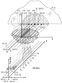
- the definition of the treatment volume includes first, as illustrated schematically in Figures 1(a) , 1(b), 3(a), and 3(b) , defining a boundary inscribing the treatment volume (V).
- An upstream plane (Y,Z)j is the plane (Y,Z) of a slice (Tj) which is first hit by the beam (100.i).
- the depth of the treatment volume (V) measured along the irradiation axis (X) is comprised between a shortest water equivalent thickness (d0) and longest water equivalent thickness (d1) measured from a skin (3s) of a patient, which correspond to the points of the boundary closest to and furthest away from the skin (3s), respectively, measured along the irradiation axis (X).
- the treatment volume (V) inscribed within the boundary is divided by defining an array of subvolumes (Vi).
- Each subvolume (Vi) extends parallel to the corresponding beam axes (Xi) from the skin of the patient to the corresponding furthest water equivalent thickness (d1), and whose projection onto a plane (Y,Z) normal to the irradiation axis (X) defines an array of spots (Si) covering a whole area of a projection of the volume (V) onto the plane (Y,Z) (cf. Figure 1(a) ).
- the subvolumes (Vi) are themselves divided into cells (Cij) as follows.
- a cell (Cij) is defined as a portion of the subvolume (Vi) comprised within the corresponding slice (Tj), This is illustrated in Figures 1(a) , 3(a), and 3(b) .
- a cell water equivalent thickness (dij) is determined from the skin (3s) to a geometrical centre of the cells (Cij).
- a beam weight ( ⁇ ij) is attributed to each cell (Cij) required for depositing into the cell (Cij) the specific dose (Dij) according to the TP.
- the beam weight ( ⁇ ij) corresponds to the number of charged particles (e.g., protons) to be delivered within a spot (Cij).
- the beam weight ( ⁇ ij) is therefore proportional to the number of charged particles at the cell water equivalent thickness (dij).
- the ridge filter (11) can be designed and dimensioned accordingly as follows.
- the ridge filter (11) comprises a set of energy degrading units (11.i) configured for reducing an initial energy (E0) of a beam (100.i) of charged particles of beam diameter (D100.i), coaxial with the corresponding beam axes (Xi) and subvolume (Vi) to reduced energies (Eij), such that the specific doses (Dij) are deposited at the cell water equivalent thicknesses (dij) into the corresponding cells (Cij) comprised within the subvolume (Vi) according to the TP.
- the principle is illustrated in Figures 2(a) and 2(b) .
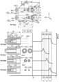
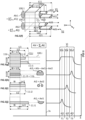
- Figure 2(a) plots the dose (Dij) deposited as a function of the WET along a beam axis (Xi) by a beam (100.i) of given energy (E0).
- the maximum beam range in water (WET) is defined as WO, corresponding to the depth beyond the maximum of the Bragg peak and corresponding to an energy equal to 80% of the maximum of the Bragg peak. This means that the beam (100.i) of given energy cannot penetrate deeper into the tissues than the corresponding water equivalent thickness WO (i.e., d1 ⁇ WO). If d1 > WO, i.e., the treatment volume (V) extends deeper than the Bragg peak, then a beam of higher energy must be used.
- Figure 2(b) shows the displacement of the Bragg peak upon inserting a degrading subunit (11.ij) across the path of the same beam (100.i) of given energy. It can be seen that the WET of the Bragg peak is now at a depth (dij ⁇ WO) from the skin (3s). This is because a portion (E0 - Eij) of the energy of the beam (100.i) is absorbed by the degrading subunit (11.ij) the beam must cross.
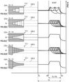
- Each Bragg peak of the given beam (100.i) has a corresponding energy degrading unit (11.i) whose degrading subunits (11.ij) can be designed to yield the required SOBP and thus deposit the required doses (Dij) into the corresponding cells (Cij).
- N ⁇ degrading subunits (11.ij) as illustrated in Figures 6(c) and 6(e) the steps of the stepped configuration of the energy degrading unit (11.i) become smaller until tending to zero, yielding the smooth geometry of a truncated generalized cone illustrated in Figures 6(c) and 6(e) , wherein a generalized cone can have a base of any geometry, not restricted to a circle.
- Each degrading subunit (11.ij) has a generalized cylindrical geometry (i.e., not necessarily a circular cylinder) of base of area (Aij) normal to the corresponding beam axis (Xi) and of generatrixes of length (Lij) parallel to the corresponding beam axis (Xi).
- the degrading subunits illustrated in Figures 4(a) to 4(e) and 5(a) to 5(e) have a circular or polygonal cross-section. It is clear that other cross-sections are possible. A certain degree of symmetry of the cross-sections is, however, preferred to facilitate the calculation of the dimensioning of the areas (Aij).
- the degrading subunits are made of materials having a subunit water equivalent thickness per unit length (Wu) along the corresponding beam axis (Xi).
- the length (Lij) and area (Aij) of each degrading subunit (11.ij) can be dimensioned as follows.
- the fluence of a beam of charged particles generally has a Gaussian distribution.
- the diameter (D100) of a beam can be defined as the distance 4 ⁇ , wherein ⁇ is the standard deviation of the Gaussian distribution characterizing the fluence of the beam. Approximately 95% of the protons of the spots are located within this diameter of 4 ⁇ .
- an array of spots is defined covering an area of a projection parallel to the irradiation axis (X) of the treatment volume (V) onto a projection plane (Y,Z) normal to the irradiation axis (X).
- the oncologist defines a treatment plan defining the doses (Dij) to be deposited into the treatment volume (V) as well as the doses depositions not to be exceeded in the healthy cells located outside (in particular upstream) of the treatment volume.
- the spots have a dimension normal to the irradiation axis (X), which can be equal to the beam diameter discussed supra.
- the distance between adjacent spots, defining the array density, is an important parameter, since the denser the array (i.e., the closer adjacent spots are from one another) the more substantial is the effect of overlapping doses to the cells spanned by adjacent spots. A substantial overlap leading to a uniform lateral dose distribution is observed at distances between adjacent spots of about 1.5 ⁇ .
- the spots (Si) of the array of spots are separated from one another by a distance (ds) smaller than or equal to 1.8 times the standard deviation ( ⁇ ) of the fluence (Fi(y,z)) of the beam (100.i) at one single spot (i.e., ds ⁇ 1.8 ⁇ ), preferably smaller than or equal to 1.5 ⁇ .
- a given subvolume (Vi) receives doses (Dij) from the beam (100.i) centred on the corresponding beam axis (Xi) but also from neighbouring beams centred on adjacent beam axes and whose fluence extends over the given subvolume (Vi) and also extends over the given degrading unit 11.i.
- the fluence (F(y,z)) of the beams (100.i) going through the base area (Abi) is approximated to being constant over all values of the planes (Y, Z)j of the slices (Tj) defining the boundary inscribing the volume (V).
- the spots (Si) of the array of spots are separated from one another by a distance (ds) larger than 1.2, preferably larger than 1.5 times a standard deviation ( ⁇ ) of the fluence (Fi(y,z)) of the beam (100.i) at a single spot (100.i) (i.e., ds > 1.2 ⁇ ).
- ds a distance
- ⁇ standard deviation
- the fluences of adjacent beams through a given degrading unit (11.i) is negligible.
- Increasing the density of the array of spots (Si) may seem to always be advantageous over a low-density array. Irradiating a high-density array, however, prolongs the scanning time required to cover the whole treatment volume (V). Furthermore, FLASH deposition wherein doses (Dij) are to be deposited at HDR to yield a FLASH-effect to spare the healthy cells, is more difficult to yield with a high-density array because of doses being deposited from adjacent beams, thus prolonging the deposition time (and decreasing the deposition rate accordingly). The density of the array of spots (Si) is therefore to be determined case by case.
- the principle of the ridge filter (11) of the present invention is for each spot (Si) to degrade the energy of the beam (100.i) such as to yield a desired SOBP in the corresponding subvolume (Vi), with an extended peak extending between the shortest water equivalent thickness (d0) and longest water equivalent thickness (d1) measured from the skin (3s) of the patient, bounding the portion of the subvolume (Vi) comprised within the treatment volume.
- the challenge is to degrade the energy of only a fraction of the beam (100.i) such as to move the Bragg peaks of predetermined beam weight fractions ( ⁇ ij ) of the whole weight ( ⁇ i ) of the beam (100.i) to the corresponding cell water equivalent thicknesses (dij), so that the desired doses (Dij) be deposited into the corresponding cells (Cij) of the corresponding suvolumes (Vi).
- the energy degrading units (11.i) are in the form of orifices arranged side-by-side according to the array of spots (Si) in a support base (11b) of thickness (Bi) measured along the beam axis (Xi). Each orifice extends from an aperture opening at a surface of the support base (11b) and penetrates to a given depth measured along the corresponding beam axes (Xi).
- the degrading subunits are arranged in a construction in series, wherein the degrading subunits (11.ij) are aligned along the corresponding beam axis (Xi), by order of decreasing lengths (Lsij).
- the degrading subunits (11.ij) are preferably arranged coaxially and with the orifice having the longest length (Lsi3) being positioned at a central position. They can also be arranged in other configurations, e.g., not concentrically, and with the orifice of longest length (Li3) not being necessarily centred.
- the subunit base area (Aij) of each degrading subunit (11 .ij) with the exception of the subunit base area (Ai3) of deepest orifice (11.i3) has an annular geometry.
- the subunit base area (Aij) of a given degrading subunit (11.ij) is equal to a difference of cross sectional areas (Axij - Axi(j + 1)) of the cross-sectional area (Axij) between the given degrading unit (11.ij) and the cross-sectional area (Axi(j+1)) of the degrading unit (Axi(j+1)) circumscribed within the given degrading unit, wherein the cross-sectional area (Axij) of a degrading subunit (11 .ij) is the cross-sectional area of an orifice normal to the corresponding beam axis (Xij) comprised within an outer perimeter of the cross-section of the degrading subunit (11.ij).
- the degrading subunits can be arranged in a construction in parallel.
- the degrading subunits are arranged side-by-side within the base area (Abi), either without spaces between two degrading subunits as illustrated for pins in Figures 7(e) and 7(g) (it is easy to imagine the corresponding design with orifices), or with a space between two adjacent degrading subunits as shown in Figures 4(f) and 4(g) ,
- the degrading subunits can be arranged in a series and parallel mixed construction.
- this construction illustrated for pins in Figures 7(h) and 7(i) (it is easy to imagine the corresponding design with orifices), three or more degrading subunits (11.ij) are arranged both in series and in parallel, with one or more structures formed by two or more degrading subunits aligned in series along the corresponding beam axis (Xi) and, optionally; one or more individual degrading subunits, are arranged side-by-side within the base area (Abi).
- This embodiment is particularly easy to produce, either by machining or etching a block forming the support base (11b) or by forming it by a 3D-printing technique.
- Using orifices rather than pins has the advantage that the weight attributed to the Bragg peak matches the fluence of the spots. Indeed, the Bragg peak with the larger range is usually the one with the larger weight ( ⁇ ij ) in the treatment plan.
- the corresponding subunit i.e. with the smallest length Li
- the subunit with the largest length Li will correspond to the Bragg peak (with the shortest range) with usually a small weight and therefore a small cross section. It is therefore convenient that it be located in the region of the spot with the smallest fluence.
- Forming an orifice with tight tolerances is easier than forming a thin pin of length (Lij) with the same tolerances, required to yield the desired effect. Offsetting the degrading subunit of longest length (Lij) can also contribute to decreasing the weight of slight deviations in manufacturing.
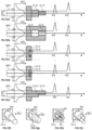
- Figures 4(a) to 4(e) show an energy degrading unit (11.i) formed of three degrading subunits (11.ij) and Figure 7(b) show an energy degrading unit (11.i) formed of two degrading subunits (11.ij) only. It is clear that the number (N) of degrading subunits can in practice be higher to yield a smoother SOBP plateau.
- Figures 6(a) to 6(c) show similar energy degrading units (11.i) comprising three, six, an "infinite number" of degrading subunits (11.ij), the latter forming a trunco-conical orifice.
- each degrading subunit is illustrated separately and, in its entirety forming generalized hollow cylinders, which are fitted into one another to form the degrading subunit of Figure 4(b) .
- the degrading subunit (11.ij) of Figure 4(b) can be produced either by machining or etching a support base (11b) to form the orifices or by forming the ridge filter by 3D-printing techniques, with corresponding orifices.
- the energy degrading units (11.i) are in the form of pins arranged side-by-side according to the array of spots (Si) and supported on a support base (11b) of thickness (Bi) measured along the beam axis (Xi). Each pin extends from the support base along the corresponding beam axes (Xi).
- the degrading subunits (11.ij) are arranged in series.
- the degrading subunits are aligned along the corresponding beam axis (Xi), by order of decreasing lengths (Lsij). They are preferably arranged coaxially and with the pin having the longest length (Lsi1) being positioned at a central position.
- the subunit base area (Aij) of a given degrading subunit (11.ij) is equal to a difference of cross sectional areas (Axij - Axi(j - 1)) of the cross-sectional area (Axij) between the given degrading unit (11.ij) and the cross-sectional area (Axi(j-1)) of the degrading unit (Axi(j-1)) circumscribed within the given degrading unit.
- the pins are in the shape of stepped pyramids (cf. Fiures 4(b) to 4(e)).
- the area (Aij) of a given degrading subunit (11.ij) is the area of the tread (or flange) of the step formed by the given degrading subunit (11.ij), surrounding the next degrading subunit (11.i(j+1)) of smaller dimensions than the given degrading subunit (11.ij).
- the degrading subunits can be arranged in construction in parallel.
- the degrading subunits are arranged side-by-side within the base area (Abi), either without spaces between two degrading subunits as illustrated in Figures 7(e) and 7(g) , or with a space between two adjacent degrading subunits as shown in Figures 5(f) and 5(g) ,
- the degrading subunits are arranged side-by-side, with the longest degrading subunit being preferably offset relative to the corresponding beam axis (Xi).
- the longest degrading unit faces a portion of the beam (100.i) with lower weight and the cross-sectional areas (Aij) can therefore be larger, thus facilitating the manufacturing of the energy degrading unit (11.i).
- the same configuration can also be applied to energy degrading units (11.i) in the form of orifices, discussed supra.
- three or more degrading subunits can be arranged both in series and in parallel in a mixed construction.
- three or more degrading subunits (11.ij) are arranged both in series and in parallel, with one or more structures formed by two or more degrading subunits aligned in series along the corresponding beam axis (Xi) and, optionally; one or more individual degrading subunits, are arranged side-by-side within the base area (Abi).
- Figures 5(a) to 5(e) and 7(f) show an energy degrading unit (11.i) formed of three degrading subunits (11.ij) and Figures 7(a) and 7(e) show energy degrading units (11.i) formed of two degrading subunits (11.ij) only. It is clear that the number (N) of degrading subunits can in practice be higher to yield a smoother SOBP plateau.
- the energy degrading units (11.i) in the form of pins can comprise any number, such as three, six, an "infinite number" of degrading subunits (11.ij), the latter forming a truncated cone (cf. Figure 6(e) ). Regardless of the number N of degrading subunits (11.ij), all pins have a base area (Ai1) and a tip area (Ai3), and of length (Lsi3) (cf. Figures 5(a) to 5(e) for the meaning of the symbols).
- each degrading subunit is illustrated separately and, in its entirety, and are fitted into one another to form the degrading subunit in Figure 5(b) .
- the degrading subunit (11.ij) of Figure 5(b) can be produced by machining, etching, or 3D-printing a monolithic energy degrading unit (11.i), preferably with the support base (11b), or each degrading subunit (11.ij) individually and assembling them subsequently to form an energy degrading unit (and base support (11b)).
- the whole ridge filter is produced monolithically (i.e., requiring no assembly step).
- a first degrading subunit (11.11) of a first energy degrading unit (11.1) is made of a first material different from a second material of a second degrading subunit (11.ij) of the first or of a second energy degrading unit (11.1, 11.2).
- the first material having a value of the subunit water equivalent thickness per unit length (Wu) which is different from the second material, such as to vary, preferably decrease the value of the length (L11 W11 / Wu) of the first degrading subunit (11.11), compared with the length of a corresponding first energy subunit (11.11) made of the second material.
- Figure 7(c) shows an embodiment comprising first and second degrading subunits (11.i1, 11.i2) arranged concentrically.
- the second degrading subunit (11.i2) is enclosed within an annular first degrading subunit (11.i1).
- the first degrading subunit (11.i1) is made of a first material having a subunit water equivalent thickness per unit length (Wu) higher than the material forming the second degrading subunit (11.i2).
- the first degrading subunit (11.i1) absorbs more energy from the beam and results in a shift of the Bragg peak to a cell with a smaller cell water equivalent thickness (di1 ⁇ di2), lower than the cell water equivalent thickness (di2) crossing the second degrading subunit (11.i2).
- This embodiment combining different materials having different subunit water equivalent thicknesses per unit length (Wu) can be applied to both cavity- and pin-shaped energy degrading units (11.i) to reduce the lengths (Lij) of the longest degrading subunits (11.ij) and increasing the lengths of the shortest degrading subunits (11.ij) to yield a shorter ridge filter (11) and to facilitate production and respect of tolerances, but selecting the dimensions most convenient for production.
- the choice of materials for each degrading subunit may be driven by the objective of yielding the length (L11) of the first degrading subunit (11.11) to be within ⁇ 20% of the length of the second degrading subunit (Lij), and so on.
- a ridge filter (11) is formed by a plurality of energy degrading units (11.i) arranged side by side on a base support (11b).
- the positions of the individual energy degrading units (11.i) correspond to the positions of the corresponding spots (Si), and their orientations is parallel to the corresponding beam axes (Xi).
- All the beam axes (Xi) are represented parallel to each other in Figures 1(a) , 1(b), 3(a) , and 3(e) . This is not exactly correct, since all the beam axes (Xi) initiate from a same point at the centre of the scanning magnets in the nozzle and are deviated to scan all the spots (Si) characterizing the treatment volume (V). This is represented in Figures 3(b), 3(d) , and 3(f) , wherein the angles of deviation are exaggerated forsake of clarity.
- the aperture angle of the cone enclosing all beam axes (Xi) depends on the distance between the scanning magnet and the treatment volume (V) and on the size of the treatment volume (V).
- Figure 3(b) shows a view of the irradiation system corresponding to the view of Figure 3(a) , with the beam axes deviating from parallelism, taking account of the scanning effect of the beams.
- the aperture angle is exaggerated in Figure 3(b).
- Figure 3(c) shows a corresponding ridge filter (11) with pins jutting out of a support base (11b) and deviating from parallelism relative to one another.
- Figure 3(d) shows two energy degrading units formed by two corresponding orifices in the support base (11b).
- the aperture angle is exaggerated for sake of clarity.
- the aperture angle is generally within ⁇ 5°, preferably within ⁇ 3°, more preferably within ⁇ 1° from the irradiation axis (X). For this reason, although not strictly correct, representing the beam axes (Xi) parallel to one another in the Figures is an acceptable simplification of reality.
- the subvolumes (Vi) extend (substantially) parallel to one another and to the irradiation axis (X), and in Figure 3(f) , the subvolumes extend along diverging beam axes (Xi) (again, the aperture angle is exaggerated for sake of clarity).
- the longest degrading subunit (11.i1) therefore determines the shortest cell water equivalent thickness (di1) defining the position of the Bragg peak closest to the skin (3s) of the patient.
- the shortest degrading subunit (11.iN) of shortest length (LiN) which determines the cell water equivalent thickness (diN) of the Bragg peak most remote from the skin (3s) of the patient.
- the normalized beam weight ( ⁇ ij ) is equated to the normalized value of the integral of the beam fluence (F(y, z)) over the area (Aij) to be dimensioned.
- the area (Aij) defines the boundary over which the integral at the numerator of Equation (1) is calculated, the area (Aij) can be determined for each degrading subunit (11.ij).
- a preferred arrangement of the individual degrading subunits (11.ij) is to assemble them coaxially to form a corresponding energy degrading unit (11.i) (cf. Figures 4(a) to (e) and 5(a) to (e) ).
- the area (Aij) of a first degrading subunit (11.ij) has an annular geometry forming an annular step around the degrading subunit (11.i(j+1)) inscribed coaxially within the first degrading subunit.
- the areas (Aij) of the degrading subunits (11.ij) are the areas at a base of each degrading subunit.
- Equation (1) e ⁇ y ⁇ y i 2 ⁇ y 2 + z ⁇ z i 2 ⁇ z 2 ,
- the method proposed herein to design and dimension a ridge filter (11) for single layer PBS painting of a treatment volume (V) is simple, reliable, and reproducible.
- the design with energy degrading units (11.i) in the form of cavities is more robust to production tolerances than pins formed by concentric degrading subunits (11.ij), as the central degrading subunit (11.i1) is at the same time the longest and thinnest of the whole energy degrading unit (11.i), rendering the accurate production thereof more complex. Configurations other than concentric are possible, such as stacked, reducing somehow this issue.
- the use of materials having a higher subunit water equivalent thickness per unit length (Wu) for the degrading subunits (11.ij) of longest lengths (Lij) is also a solution to reduce the problem of accurate production of long thin pins.
- an array of the spots (Si) can be defined as described supra, and the treatment volume (V) can be divided into subvolumes (Vi) (one per spot) and the subvolumes (Vi) into N cells (Cij) accordingly.
- the doses (Dij) to be deposited into the cells (Cij) are determined based on the treatment plan.
- the ridge filter is designed comprising the same number of energy degrading units (11.i) as there are spots (Si). Each energy degrading unit (11.i) is formed by N degrading subunits (11.ij) of lengths (Lij) and area (Aij).
- the lengths (Lij) must take account of the thickness (Bi) of the support block (11b) supporting all the energy degrading units (11.i).
- the area (Aij) of each degrading subunit (11.ij) is obtained by determining the area (Aij) over which the integral at the numerator of Equation (1) is computed. This operation can be carried out numerically.
- the individual energy degrading units (11.i) are arranged on a support block (11b), such as to extend coaxially along the respective beam axes (Xi).
- the ridge filter can be produced by machining a block, by attaching individual pins to a support block (11b), by 3D-printing techniques and the like.
- the ridge filter (11) thus produced can be installed between the outlet of the accelerator of charged particles and the treatment volume (V) such that each subvolume (Vi) be coaxial with the corresponding beam axis (Xi). Irradiation by single layer PBS painting can start.
- the ridge filter (11) designed by the method of the present invention is particularly suitable for treatment plans including FLASH-irradiation of at least a portion of the treatment volume (V) requiring doses (Dij) to be deposited into cells (Cij) at ultra-high deposition rates (HDR), by PBS, as it allows the whole treatment volume to be covered with a single paint layer, thus decreasing substantially the scanning time required to deposit doses (Dij) into each slice (Tj).
Landscapes
- Health & Medical Sciences (AREA)
- Engineering & Computer Science (AREA)
- Biomedical Technology (AREA)
- Pathology (AREA)
- Nuclear Medicine, Radiotherapy & Molecular Imaging (AREA)
- Radiology & Medical Imaging (AREA)
- Life Sciences & Earth Sciences (AREA)
- Animal Behavior & Ethology (AREA)
- General Health & Medical Sciences (AREA)
- Public Health (AREA)
- Veterinary Medicine (AREA)
- Physics & Mathematics (AREA)
- Spectroscopy & Molecular Physics (AREA)
- General Engineering & Computer Science (AREA)
- High Energy & Nuclear Physics (AREA)
- Radiation-Therapy Devices (AREA)
Claims (10)
- Procédé pour concevoir un filtre en peigne d'un accélérateur de particules chargées, de préférence un accélérateur de protons, pour déposer avec des faisceaux de particules accélérées (100.i) des doses spécifiques (Dij) dans des emplacements spécifiques à l'intérieur du volume de traitement (V) de tissu comportant des cellules tumorales (3t) par balayage par faisceau filiforme ou « pencil beam scanning » (PBS), point par point (Si) selon un plan de traitement prédéfini (TP), dans une seule couche de peinture définissant le volume de traitement tout entier (V), les faisceaux (100.i) s'étendant le long d'axes de faisceaux correspondants (Xi) essentiellement parallèles à un axe d'irradiation (X), divergeant du parallélisme avec l'axe d'irradiation (X) d'un angle compris dans ± 5°, de préférence dans ± 3°, et le tissu étant caractérisé par une portée de faisceau maximum (W0), définie comme la distance équivalente en eau à laquelle le faisceau arrête de se propager à travers le tissu, ce procédé comprenant les étapes suivantes :• la définition d'une enveloppe circonscrivant le volume de traitement (V) en définissant des aires (Aj) sur des plans amont (Y, Z) de N tranches (Tj = T1 - TN) d'une épaisseur (dxj), les plans (Y, Z) étant normaux à l'axe d'irradiation (X), dans lequel une épaisseur équivalente en eau la plus courte (d0) et une épaisseur équivalente en eau la plus longue (d1) jusqu'à une peau d'un patient sont définies comme les endroits de l'enveloppe les plus proches et les plus éloignés de la peau, respectivement, mesurés le long de l'axe d'irradiation (X),• la définition d'une matrice de sous-volumes (Vi), chaque sous-volume s'étendant parallèlement aux axes des faisceaux correspondants (Xi) depuis la peau du patient jusqu'à l'épaisseur équivalente en eau la plus éloignée correspondante (d1), et dont la projection sur un plan (Y, Z) normal à l'axe d'irradiation (X) définit une matrice de points (Si) couvrant une surface entière d'une projection du volume (V) sur le plan (Y, Z),• pour chaque tranche (Tj) des N tranches (T1 - TN), comprise à l'intérieur d'un sous-volume (Vi), la définition d'une cellule (Cij) définie comme une partie du sous-volume (Vi) comprise à l'intérieur de la tranche correspondante (Tj),• pour chaque cellule (Cij) du sous-volume donné (Vi), la détermination d'une épaisseur équivalente en eau (dij) de cellule depuis la peau (3s) jusqu'à un centre géométrique des cellules (Cij), et l'attribution d'un poids de faisceau (ωij) requis pour déposer dans la cellule (Cij) la dose spécifique (Dij) selon le plan de traitement (TP), le poids du faisceau (ωij) étant proportionnel au nombre de particules chargées à l'épaisseur équivalente en eau (dij) de la cellule,• la conception du filtre en peigne (11) avec un ensemble d'unités de dégradation d'énergie (11.i), chaque unité de dégradation d'énergie (11.i) étant configurée de façon à réduire une énergie initiale (E0) d'un faisceau correspondant (100.i) de particules chargées d'un diamètre de faisceau (D100.i), coaxial avec les axes des faisceaux correspondants (Xi), et le sous-volume (Vi) en des énergies réduites (Eij), de manière à ce que les doses spécifiques (Dij) soient déposées aux épaisseurs équivalentes en eau (dij) des cellules dans les cellules correspondantes (Cij) comprises à l'intérieur du sous-volume (Vi) selon le TP, l'unité de dégradation d'énergie (11.i) d'un sous-volume donné (Vi) étant conçue de la manière suivante :o pour chaque cellule (Cij) du sous-volume (Vi), le dimensionnement d'une sous-unité de dégradation (11.ij) ayant une géométrie cylindrique généralisée de la base d'une surface (Aij) normale à l'axe de faisceau correspondant (Xi) et de génératrices d'une longueur (Lij) parallèles à l'axe du faisceau correspondant (Xi), cette sous-unité de dégradation étant faite en un matériau ayant une épaisseur équivalente en eau de sous-unité par unité de longueur (Wu) le long de l'axe du faisceau correspondant (Xi), la longueur (Lij) étant déterminée de manière à ce que la sous-unité de dégradation (11.i) ait une épaisseur équivalente en eau de sous-unité (Wij = Wu x Lij) égale à un produit de l'épaisseur équivalente en eau de sous-unité par unité de longueur (Wu) et de la longueur (Lij), une somme de l'épaisseur équivalente en eau de sous-unité (Wij) et de l'épaisseur équivalente en eau de cellule (dij) étant égale à la plage de faisceau maximum (W0) (c'est-à-dire que W0 = Wij + dij), eto la surface (Aij) d'une sous-unité de dégradation (11.ij) est déterminée en mettant en équation un poids de faisceau normalisé (ωij / Σ j ωij) avec un rapport entre une intégrale d'une fluence (F(y, z)) sur la surface de la base de la sous-unité (Aij) et la même intégrale sur une surface de base (Abi) de l'unité de dégradation (11.i),
 o la combinaison des N sous-unités de dégradation (11.ij) afin d'obtenir l'unité de dégradation d'énergie (11.i) conçue pour dégrader l'énergie du faisceau (100.i) de manière à déposer les doses requises (Dij) dans le sous-volume (Vi),• la conception des unités de dégradation d'énergie (11.i) correspondant à tous les sous-volumes (Vi) restants tels que définis ci-dessus,l'expression « épaisseur équivalente en eau » ou « water equivalent thickness » en anglais (= WET) étant définie comme une épaisseur d'eau causant une même dégradation d'énergie d'un faisceau de particules qu'une épaisseur donnée d'un ou de plusieurs matériaux traversés par le faisceau de particules.
 - Procédé selon la revendication 1, dans lequel les doses spécifiques (Dij) doivent être déposées selon le plan de traitement à une vitesse de dépôt de dose (HDR) ultra-élevée dans au moins une sélection des emplacements spécifiques à l'intérieur du volume (V) de tissu, la HDR étant définie comme une vitesse de dépôt de dose, HDR ≥ 1 Gy / s.
- Procédé selon la revendication 1 ou 2, dans lequel les points (Si) de la matrice de points sont séparés les uns des autres par une distance (ds) plus petite que ou égale à 1,8 fois un écart type (σ) de la fluence (Fi(y, z) du faisceau (100.i) en un seul point (c'est-à-dire que ds ≤ 1,8 σ), de préférence plus petite que ou égale à 1,5 σ, et dans lequel la fluence (Fi(y, z) du faisceau (100.i) traversant la surface de la base (Abi) est approximée comme étant constante sur toutes les valeurs des plans (Y, Z)j définissant l'enveloppe circonscrivant le volume (V).
- Procédé selon la revendication 1 ou 2, dans lequel les points (Si) de la matrice de points sont séparés les uns des autres par une distance (ds) plus grande que 1,2 fois, de préférence plus grande que 1,5 fois un écart type (σ) de la fluence (Fi(y, z) du faisceau (100.i) en un seul point (100.i) (c'est-à-dire que ds > 1,2 σ), et dans lequel la fluence (Fi(y, z) du faisceau (100.i) traversant la surface de la base (Abi) est approximée comme étant une Gaussienne,

- Procédé selon l'une quelconque des revendications précédentes 1 à 4, dans lequel• les unités de dégradation d'énergie (11.i) sont sous la forme d'orifices disposés côte à côte selon la matrice de points (Si) dans une base de support (11b) d'une épaisseur (Bi) mesurée le long de l'axe du faisceau (Xi), chaque orifice s'étendant depuis une ouverture située à une surface de la base de support (11b) et pénétrant jusqu'à une profondeur donnée le long des axes des faisceaux correspondants (Xi), dans lequel• chaque unité de dégradation d'énergie (11.i)o est formée par une ou plusieurs sous-unités de dégradation (11.ij, 11.13, 11.12, 11.11) sous la forme d'orifices ayant une géométrie cylindrique généralisée de surfaces de sections transversales (Ai) et s'étendant le long d'un axe de faisceau correspondant (Xi) depuis l'ouverture dans le bloc de support (11b) sur les longueurs (Lsij), de telle sorte que Lij = Bi - Lsij, et dans lequelo les sous-unités de dégradation (11.ij, 11.13, 11.12, 11.11) sont disposées à l'intérieur de la surface de la base (Abi).
- Procédé selon la revendication 5, dans lequel une unité de dégradation d'énergie (11.i) comporte au moins deux sous-unités (11.ij) qui sont disposées à l'intérieur de la surface de la base (Abi) dans une des configurations suivantes :• dans une construction en série, dans laquelle∘ les sous-unités de dégradation sont alignées le long des axes des faisceaux correspondants (Xi), par ordre de longueurs décroissantes (Lsij), de préférence coaxialement et avec l'orifice ayant la longueur la plus longue (Lsi3) étant positionné dans une position centrale, et dans laquelleo la surface de la base de sous-unité (Aij) d'une sous-unité de dégradation donnée (11.ij) est égale à une différence des surfaces de sections transversales (Axij - Axi(j + 1)) de la surface de section transversale (Axij) entre l'unité de dégradation donnée (11.ij) et la surface de section transversale (Axi(j + 1) de l'unité de dégradation d'énergie (11.i) circonscrite à l'intérieur de l'unité de dégradation donnée,• dans une construction en parallèle, dans laquelle les sous-unités de dégradation sont disposées côte à côte à l'intérieur de la surface de la base (Abi), soit sans espaces entre deux sous-unités de dégradation, soit avec un espace entre deux sous-unités de dégradation adjacentes,• dans une construction mixte à la fois en parallèle et en série, dans laquelle trois sous-unités de dégradation (11.ij) ou plus sont disposées à la fois en série et en parallèle, dans laquelle une ou plusieurs structures formées par deux sous-unités de dégradation ou plus sont alignées en série le long de l'axe du faisceau correspondant (Xi) et, facultativement, dans laquelle une ou plusieurs sous-unités de dégradation individuelles sont disposées côte à côte à l'intérieur de la surface de la base (Abi).
- Procédé selon l'une quelconque des revendications précédentes 1 à 4, dans lequel• les unités de dégradation d'énergie (11.i) sont sous la forme de tiges disposées côte à côte selon la matrice de points (Si) et supportées sur une base de support (11b) d'une épaisseur (Bi) mesurée le long de l'axe du faisceau (Xi), chaque tige s'étendant depuis la base de support le long des axes des faisceaux correspondants, dans lequel• chaque unité de dégradation d'énergie (11.i)o est formée par une ou plusieurs sous-unités de dégradation (11.ij, 11.13, 11.12, 11.11) ayant une géométrique cylindrique généralisée de surfaces de sections transversales (Aij), et s'étendant le long de l'axe du faisceau correspondant (Xi) depuis la base de support sur des longueurs (Lsij), de telle sorte que Lij = Bi - Lsij, dans lequelo les sous-unités de dégradation (11.ij, 11.13, 11.12, 11.11) sont disposées à l'intérieur de la surface de la base (Abi).
- Procédé selon la revendication 7, dans lequel une unité de dégradation d'énergie (11.i) comporte au moins deux sous-unités (11.ij) qui sont disposées à l'intérieur de la surface de la base (Abi) dans une des configurations suivantes :• dans une construction en série, dans laquelle∘ les sous-unités de dégradation sont alignées le long des axes des faisceaux correspondants (Xi), par ordre de longueurs décroissantes (Lsij), de préférence coaxialement et avec la tige ayant la longueur la plus longue (Lsi1) étant positionnée dans une position centrale, et dans laquelleo la surface de la base de sous-unité (Aij) d'une sous-unité de dégradation donnée (11.ij) est égale à une différence de surfaces de sections transversales (Axij - Axi(j - 1)) de la surface de section transversale (Axij) entre l'unité de dégradation donnée (11.ij) et la surface de section transversale (Axi(j - 1) de l'unité de dégradation (11.i) circonscrite à l'intérieur de l'unité de dégradation donnée,• dans une construction mixte à la fois en parallèle et en série, dans laquelle trois sous-unités de dégradation (11.ij) ou plus sont disposées à la fois en série et en parallèle, dans laquelle une ou plusieurs structures sont formées par deux sous-unités de dégradation ou plus alignées en série le long de l'axe du faisceau correspondant (Xi) et, facultativement, dans laquelle une ou plusieurs sous-unités de dégradation individuelles sont disposées côte à côte à l'intérieur de la surface de la base (Abi).
- Procédé selon l'une quelconque des revendications précédentes 5 à 8, dans lequel au moins une première sous-unité de dégradation (11.11) d'une première unité de dégradation d'énergie (11.i) est faite en un premier matériau différent d'un deuxième matériau d'une deuxième sous-unité de dégradation (11.ij) de la première ou d'une deuxième unité de dégradation d'énergie (11.1, 11.2), le premier matériau ayant une valeur de l'épaisseur équivalente en eau de sous-unité par unité de longueur (Wu) qui est différente du deuxième matériau, de manière à varier, de préférence diminuer, la valeur de la longueur (L11 = W11 / Wu) de la première sous-unité de dégradation (11.11), par rapport à la longueur d'une première sous-unité de dégradation d'énergie correspondante (11.11) faite dans le deuxième matériau.
- Procédé selon la revendication 9, dans lequel la longueur (L11) de la première sous-unité de dégradation (11.11) correspond à ± 20 % près à la longueur de la deuxième sous-unité de dégradation (Lij), et, de préférence, les longueurs (Lij) de toutes les sous-unités de dégradation (11.ij) d'une unité de dégradation d'énergie (11.i) ont une même longueur (Lij) avec une variation de ± 20% d'une longueur moyenne (Lm,ij) (c'est-à-dire que Lij = Lm,ij ± 20% Vj).
Priority Applications (4)
| Application Number | Priority Date | Filing Date | Title |
|---|---|---|---|
| EP21208699.5A EP4183447B1 (fr) | 2021-11-17 | 2021-11-17 | Procédé de conception d`un filtre à nervure dans un système de traitement pbs |
| JP2022174047A JP2023074477A (ja) | 2021-11-17 | 2022-10-31 | Pbs治療システムにおけるリッジフィルタ及びそれを設計する方法 |
| US18/051,970 US20240131361A1 (en) | 2021-11-17 | 2022-11-02 | Ridge filter and method for designing same in a pbs treatment system |
| CN202211438206.3A CN116135255B (zh) | 2021-11-17 | 2022-11-16 | 脊形过滤器和用于在pbs治疗系统中设计脊形过滤器的方法 |
Applications Claiming Priority (1)
| Application Number | Priority Date | Filing Date | Title |
|---|---|---|---|
| EP21208699.5A EP4183447B1 (fr) | 2021-11-17 | 2021-11-17 | Procédé de conception d`un filtre à nervure dans un système de traitement pbs |
Publications (3)
| Publication Number | Publication Date |
|---|---|
| EP4183447A1 EP4183447A1 (fr) | 2023-05-24 |
| EP4183447C0 EP4183447C0 (fr) | 2024-04-10 |
| EP4183447B1 true EP4183447B1 (fr) | 2024-04-10 |
Family
ID=78676447
Family Applications (1)
| Application Number | Title | Priority Date | Filing Date |
|---|---|---|---|
| EP21208699.5A Active EP4183447B1 (fr) | 2021-11-17 | 2021-11-17 | Procédé de conception d`un filtre à nervure dans un système de traitement pbs |
Country Status (4)
| Country | Link |
|---|---|
| US (1) | US20240131361A1 (fr) |
| EP (1) | EP4183447B1 (fr) |
| JP (1) | JP2023074477A (fr) |
| CN (1) | CN116135255B (fr) |
Families Citing this family (1)
| Publication number | Priority date | Publication date | Assignee | Title |
|---|---|---|---|---|
| EP4115948B1 (fr) * | 2021-07-09 | 2023-11-29 | Ion Beam Applications | Dispositif de traitement pour l'administration d'un plan de traitement pour dépôt flash avec un accélérateur de particules chargées par balayage à faisceau filiforme |
Family Cites Families (9)
| Publication number | Priority date | Publication date | Assignee | Title |
|---|---|---|---|---|
| US8304751B2 (en) * | 2008-05-12 | 2012-11-06 | Mitsubishi Electric Corporation | Charged particle beam irradiation apparatus |
| US8309939B2 (en) * | 2008-05-13 | 2012-11-13 | Mitsubishi Electric Corporation | Particle beam treatment apparatus and particle beam treatment method |
| US8766217B2 (en) * | 2008-05-22 | 2014-07-01 | Vladimir Yegorovich Balakin | Multi-field charged particle cancer therapy method and apparatus |
| WO2010060929A1 (fr) * | 2008-11-26 | 2010-06-03 | Micronic Laser Systems Ab | Lecture et écriture d’images utilisant un système d’entrelaçage bidimensionnel complexe |
| US8466428B2 (en) * | 2009-11-03 | 2013-06-18 | Mitsubishi Electric Corporation | Particle beam irradiation apparatus and particle beam therapy system |
| CN101763909B (zh) * | 2010-01-20 | 2011-12-28 | 中国科学院近代物理研究所 | 一种利用高能离子束辐照时减小离子束展宽Bragg峰后沿剂量半影的方法 |
| WO2013160379A1 (fr) * | 2012-04-25 | 2013-10-31 | Ion Beam Applications S.A. | Appareil et procédé pour vérification de faisceau d'hadrons |
| EP3305367A1 (fr) * | 2016-10-07 | 2018-04-11 | Ion Beam Applications S.A. | Appareil médical comprenant un dispositif de thérapie à l'hadron, un irm, et un système de radiographie à l'hadron |
| JP2019136167A (ja) | 2018-02-07 | 2019-08-22 | 株式会社日立製作所 | 粒子線照射装置 |
-
2021
- 2021-11-17 EP EP21208699.5A patent/EP4183447B1/fr active Active
-
2022
- 2022-10-31 JP JP2022174047A patent/JP2023074477A/ja active Pending
- 2022-11-02 US US18/051,970 patent/US20240131361A1/en active Pending
- 2022-11-16 CN CN202211438206.3A patent/CN116135255B/zh active Active
Also Published As
| Publication number | Publication date |
|---|---|
| EP4183447C0 (fr) | 2024-04-10 |
| EP4183447A1 (fr) | 2023-05-24 |
| CN116135255B (zh) | 2025-03-18 |
| US20240131361A1 (en) | 2024-04-25 |
| CN116135255A (zh) | 2023-05-19 |
| JP2023074477A (ja) | 2023-05-29 |
Similar Documents
| Publication | Publication Date | Title |
|---|---|---|
| EP1641534B1 (fr) | Collimateur multi-lame | |
| EP3925666B1 (fr) | Appareil d'irradiation par particules chargées | |
| US6617598B1 (en) | Charged particle beam irradiation apparatus | |
| Weber et al. | Design and construction of a ripple filter for a smoothed depth dose distribution in conformal particle therapy | |
| US6087672A (en) | Charged particle beam irradiation system and irradiation method thereof | |
| US7054801B2 (en) | Radiation treatment plan making system and method | |
| US7295649B2 (en) | Radiation therapy system and method of using the same | |
| DE10060888A1 (de) | System und Verfahren zum Optimieren einer Strahlenbehandlung mit einem intensitätsmodulierten Mehr-Lamellen-Kollimator | |
| US11679277B2 (en) | Adjustable multi-slit collimators | |
| CN114452550A (zh) | 一种用于离子Flash治疗的束流配送系统及方法 | |
| CA2989042A1 (fr) | Collimateurs de mini-faisceaux pour accelerateurs lineaires medicaux | |
| EP4183447B1 (fr) | Procédé de conception d`un filtre à nervure dans un système de traitement pbs | |
| Shende et al. | Validation of Dosimetric Leaf Gap (DLG) prior to its implementation in Treatment Planning System (TPS): TrueBeam™ millennium 120 leaf MLC | |
| Kostjuchenko et al. | A compact ridge filter for spread out Bragg peak production in pulsed proton clinical beams | |
| Yokokawa et al. | A new SOBP-formation method by superposing specially shaped Bragg curves formed by a mini-ridge filter for spot scanning in proton beam therapy | |
| US12442780B2 (en) | Off line quality control of a beam shaping device for radiation therapy | |
| Lv et al. | Performance study of the dynamic multi-leaf collimator system (DMLC-120) | |
| JP2019136167A (ja) | 粒子線照射装置 | |
| EP4420719B1 (fr) | Filtre à crête dynamique et dispositif de décalage de plage et système de rayonnement le comprenant | |
| Chan et al. | Optimizing minibeam collimator design for enhancing normal tissue sparing in ocular tumour proton therapy | |
| EP4731303A1 (fr) | Système de collimation pour radiothérapie fractionnée spatiale et procédé de commande de collimateurs à fentes multiples | |
| JP2007267904A (ja) | 粒子線治療装置 |
Legal Events
| Date | Code | Title | Description |
|---|---|---|---|
| PUAI | Public reference made under article 153(3) epc to a published international application that has entered the european phase |
Free format text: ORIGINAL CODE: 0009012 |
|
| STAA | Information on the status of an ep patent application or granted ep patent |
Free format text: STATUS: THE APPLICATION HAS BEEN PUBLISHED |
|
| AK | Designated contracting states |
Kind code of ref document: A1 Designated state(s): AL AT BE BG CH CY CZ DE DK EE ES FI FR GB GR HR HU IE IS IT LI LT LU LV MC MK MT NL NO PL PT RO RS SE SI SK SM TR |
|
| STAA | Information on the status of an ep patent application or granted ep patent |
Free format text: STATUS: REQUEST FOR EXAMINATION WAS MADE |
|
| 17P | Request for examination filed |
Effective date: 20230606 |
|
| RBV | Designated contracting states (corrected) |
Designated state(s): AL AT BE BG CH CY CZ DE DK EE ES FI FR GB GR HR HU IE IS IT LI LT LU LV MC MK MT NL NO PL PT RO RS SE SI SK SM TR |
|
| GRAP | Despatch of communication of intention to grant a patent |
Free format text: ORIGINAL CODE: EPIDOSNIGR1 |
|
| STAA | Information on the status of an ep patent application or granted ep patent |
Free format text: STATUS: GRANT OF PATENT IS INTENDED |
|
| RIC1 | Information provided on ipc code assigned before grant |
Ipc: G21K 1/10 20060101ALI20231018BHEP Ipc: A61N 5/10 20060101AFI20231018BHEP |
|
| INTG | Intention to grant announced |
Effective date: 20231102 |
|
| GRAS | Grant fee paid |
Free format text: ORIGINAL CODE: EPIDOSNIGR3 |
|
| GRAA | (expected) grant |
Free format text: ORIGINAL CODE: 0009210 |
|
| STAA | Information on the status of an ep patent application or granted ep patent |
Free format text: STATUS: THE PATENT HAS BEEN GRANTED |
|
| AK | Designated contracting states |
Kind code of ref document: B1 Designated state(s): AL AT BE BG CH CY CZ DE DK EE ES FI FR GB GR HR HU IE IS IT LI LT LU LV MC MK MT NL NO PL PT RO RS SE SI SK SM TR |
|
| REG | Reference to a national code |
Ref country code: GB Ref legal event code: FG4D |
|
| REG | Reference to a national code |
Ref country code: CH Ref legal event code: EP |
|
| REG | Reference to a national code |
Ref country code: DE Ref legal event code: R096 Ref document number: 602021011580 Country of ref document: DE |
|
| REG | Reference to a national code |
Ref country code: IE Ref legal event code: FG4D |
|
| U01 | Request for unitary effect filed |
Effective date: 20240503 |
|
| U07 | Unitary effect registered |
Designated state(s): AT BE BG DE DK EE FI FR IT LT LU LV MT NL PT SE SI Effective date: 20240516 |
|
| PG25 | Lapsed in a contracting state [announced via postgrant information from national office to epo] |
Ref country code: IS Free format text: LAPSE BECAUSE OF FAILURE TO SUBMIT A TRANSLATION OF THE DESCRIPTION OR TO PAY THE FEE WITHIN THE PRESCRIBED TIME-LIMIT Effective date: 20240810 |
|
| PG25 | Lapsed in a contracting state [announced via postgrant information from national office to epo] |
Ref country code: HR Free format text: LAPSE BECAUSE OF FAILURE TO SUBMIT A TRANSLATION OF THE DESCRIPTION OR TO PAY THE FEE WITHIN THE PRESCRIBED TIME-LIMIT Effective date: 20240410 |
|
| PG25 | Lapsed in a contracting state [announced via postgrant information from national office to epo] |
Ref country code: GR Free format text: LAPSE BECAUSE OF FAILURE TO SUBMIT A TRANSLATION OF THE DESCRIPTION OR TO PAY THE FEE WITHIN THE PRESCRIBED TIME-LIMIT Effective date: 20240711 |
|
| PG25 | Lapsed in a contracting state [announced via postgrant information from national office to epo] |
Ref country code: ES Free format text: LAPSE BECAUSE OF FAILURE TO SUBMIT A TRANSLATION OF THE DESCRIPTION OR TO PAY THE FEE WITHIN THE PRESCRIBED TIME-LIMIT Effective date: 20240410 |
|
| PG25 | Lapsed in a contracting state [announced via postgrant information from national office to epo] |
Ref country code: PL Free format text: LAPSE BECAUSE OF FAILURE TO SUBMIT A TRANSLATION OF THE DESCRIPTION OR TO PAY THE FEE WITHIN THE PRESCRIBED TIME-LIMIT Effective date: 20240410 |
|
| PG25 | Lapsed in a contracting state [announced via postgrant information from national office to epo] |
Ref country code: PL Free format text: LAPSE BECAUSE OF FAILURE TO SUBMIT A TRANSLATION OF THE DESCRIPTION OR TO PAY THE FEE WITHIN THE PRESCRIBED TIME-LIMIT Effective date: 20240410 Ref country code: NO Free format text: LAPSE BECAUSE OF FAILURE TO SUBMIT A TRANSLATION OF THE DESCRIPTION OR TO PAY THE FEE WITHIN THE PRESCRIBED TIME-LIMIT Effective date: 20240710 Ref country code: IS Free format text: LAPSE BECAUSE OF FAILURE TO SUBMIT A TRANSLATION OF THE DESCRIPTION OR TO PAY THE FEE WITHIN THE PRESCRIBED TIME-LIMIT Effective date: 20240810 Ref country code: HR Free format text: LAPSE BECAUSE OF FAILURE TO SUBMIT A TRANSLATION OF THE DESCRIPTION OR TO PAY THE FEE WITHIN THE PRESCRIBED TIME-LIMIT Effective date: 20240410 Ref country code: GR Free format text: LAPSE BECAUSE OF FAILURE TO SUBMIT A TRANSLATION OF THE DESCRIPTION OR TO PAY THE FEE WITHIN THE PRESCRIBED TIME-LIMIT Effective date: 20240711 Ref country code: ES Free format text: LAPSE BECAUSE OF FAILURE TO SUBMIT A TRANSLATION OF THE DESCRIPTION OR TO PAY THE FEE WITHIN THE PRESCRIBED TIME-LIMIT Effective date: 20240410 Ref country code: RS Free format text: LAPSE BECAUSE OF FAILURE TO SUBMIT A TRANSLATION OF THE DESCRIPTION OR TO PAY THE FEE WITHIN THE PRESCRIBED TIME-LIMIT Effective date: 20240710 |
|
| U20 | Renewal fee for the european patent with unitary effect paid |
Year of fee payment: 4 Effective date: 20241127 |
|
| REG | Reference to a national code |
Ref country code: DE Ref legal event code: R097 Ref document number: 602021011580 Country of ref document: DE |
|
| PG25 | Lapsed in a contracting state [announced via postgrant information from national office to epo] |
Ref country code: CZ Free format text: LAPSE BECAUSE OF FAILURE TO SUBMIT A TRANSLATION OF THE DESCRIPTION OR TO PAY THE FEE WITHIN THE PRESCRIBED TIME-LIMIT Effective date: 20240410 |
|
| PG25 | Lapsed in a contracting state [announced via postgrant information from national office to epo] |
Ref country code: SK Free format text: LAPSE BECAUSE OF FAILURE TO SUBMIT A TRANSLATION OF THE DESCRIPTION OR TO PAY THE FEE WITHIN THE PRESCRIBED TIME-LIMIT Effective date: 20240410 Ref country code: RO Free format text: LAPSE BECAUSE OF FAILURE TO SUBMIT A TRANSLATION OF THE DESCRIPTION OR TO PAY THE FEE WITHIN THE PRESCRIBED TIME-LIMIT Effective date: 20240410 |
|
| PG25 | Lapsed in a contracting state [announced via postgrant information from national office to epo] |
Ref country code: SM Free format text: LAPSE BECAUSE OF FAILURE TO SUBMIT A TRANSLATION OF THE DESCRIPTION OR TO PAY THE FEE WITHIN THE PRESCRIBED TIME-LIMIT Effective date: 20240410 |
|
| PG25 | Lapsed in a contracting state [announced via postgrant information from national office to epo] |
Ref country code: SM Free format text: LAPSE BECAUSE OF FAILURE TO SUBMIT A TRANSLATION OF THE DESCRIPTION OR TO PAY THE FEE WITHIN THE PRESCRIBED TIME-LIMIT Effective date: 20240410 Ref country code: SK Free format text: LAPSE BECAUSE OF FAILURE TO SUBMIT A TRANSLATION OF THE DESCRIPTION OR TO PAY THE FEE WITHIN THE PRESCRIBED TIME-LIMIT Effective date: 20240410 Ref country code: RO Free format text: LAPSE BECAUSE OF FAILURE TO SUBMIT A TRANSLATION OF THE DESCRIPTION OR TO PAY THE FEE WITHIN THE PRESCRIBED TIME-LIMIT Effective date: 20240410 Ref country code: CZ Free format text: LAPSE BECAUSE OF FAILURE TO SUBMIT A TRANSLATION OF THE DESCRIPTION OR TO PAY THE FEE WITHIN THE PRESCRIBED TIME-LIMIT Effective date: 20240410 |
|
| PLBE | No opposition filed within time limit |
Free format text: ORIGINAL CODE: 0009261 |
|
| STAA | Information on the status of an ep patent application or granted ep patent |
Free format text: STATUS: NO OPPOSITION FILED WITHIN TIME LIMIT |
|
| 26N | No opposition filed |
Effective date: 20250113 |
|
| REG | Reference to a national code |
Ref country code: CH Ref legal event code: PL |
|
| PG25 | Lapsed in a contracting state [announced via postgrant information from national office to epo] |
Ref country code: MC Free format text: LAPSE BECAUSE OF FAILURE TO SUBMIT A TRANSLATION OF THE DESCRIPTION OR TO PAY THE FEE WITHIN THE PRESCRIBED TIME-LIMIT Effective date: 20240410 |
|
| REG | Reference to a national code |
Ref country code: CH Ref legal event code: PL |
|
| PG25 | Lapsed in a contracting state [announced via postgrant information from national office to epo] |
Ref country code: CH Free format text: LAPSE BECAUSE OF NON-PAYMENT OF DUE FEES Effective date: 20241130 |
|
| PG25 | Lapsed in a contracting state [announced via postgrant information from national office to epo] |
Ref country code: IE Free format text: LAPSE BECAUSE OF NON-PAYMENT OF DUE FEES Effective date: 20241117 |
|
| U20 | Renewal fee for the european patent with unitary effect paid |
Year of fee payment: 5 Effective date: 20251126 |
|
| PGFP | Annual fee paid to national office [announced via postgrant information from national office to epo] |
Ref country code: GB Payment date: 20251127 Year of fee payment: 5 |
|
| PG25 | Lapsed in a contracting state [announced via postgrant information from national office to epo] |
Ref country code: HU Free format text: LAPSE BECAUSE OF FAILURE TO SUBMIT A TRANSLATION OF THE DESCRIPTION OR TO PAY THE FEE WITHIN THE PRESCRIBED TIME-LIMIT; INVALID AB INITIO Effective date: 20211117 |
|
| PG25 | Lapsed in a contracting state [announced via postgrant information from national office to epo] |
Ref country code: CY Free format text: LAPSE BECAUSE OF FAILURE TO SUBMIT A TRANSLATION OF THE DESCRIPTION OR TO PAY THE FEE WITHIN THE PRESCRIBED TIME-LIMIT; INVALID AB INITIO Effective date: 20211117 |