EP4190436B1 - Mélangeur industriel - Google Patents
Mélangeur industriel Download PDFInfo
- Publication number
- EP4190436B1 EP4190436B1 EP22202208.9A EP22202208A EP4190436B1 EP 4190436 B1 EP4190436 B1 EP 4190436B1 EP 22202208 A EP22202208 A EP 22202208A EP 4190436 B1 EP4190436 B1 EP 4190436B1
- Authority
- EP
- European Patent Office
- Prior art keywords
- mixing
- mixing tool
- tool
- container
- head
- Prior art date
- Legal status (The legal status is an assumption and is not a legal conclusion. Google has not performed a legal analysis and makes no representation as to the accuracy of the status listed.)
- Active
Links
Images


Classifications
-
- B—PERFORMING OPERATIONS; TRANSPORTING
- B01—PHYSICAL OR CHEMICAL PROCESSES OR APPARATUS IN GENERAL
- B01F—MIXING, e.g. DISSOLVING, EMULSIFYING OR DISPERSING
- B01F27/00—Mixers with rotary stirring devices in fixed receptacles; Kneaders
- B01F27/80—Mixers with rotary stirring devices in fixed receptacles; Kneaders with stirrers rotating about a substantially vertical axis
-
- B—PERFORMING OPERATIONS; TRANSPORTING
- B01—PHYSICAL OR CHEMICAL PROCESSES OR APPARATUS IN GENERAL
- B01F—MIXING, e.g. DISSOLVING, EMULSIFYING OR DISPERSING
- B01F33/00—Other mixers; Mixing plants; Combinations of mixers
- B01F33/35—Mixing after turning the mixing vessel upside down
-
- B—PERFORMING OPERATIONS; TRANSPORTING
- B01—PHYSICAL OR CHEMICAL PROCESSES OR APPARATUS IN GENERAL
- B01F—MIXING, e.g. DISSOLVING, EMULSIFYING OR DISPERSING
- B01F33/00—Other mixers; Mixing plants; Combinations of mixers
- B01F33/80—Mixing plants; Combinations of mixers
- B01F33/82—Combinations of dissimilar mixers
- B01F33/823—Combinations of dissimilar mixers in two or more alternative mixing receptacles, e.g. mixing in one receptacle and dispensing from another receptacle
-
- B—PERFORMING OPERATIONS; TRANSPORTING
- B01—PHYSICAL OR CHEMICAL PROCESSES OR APPARATUS IN GENERAL
- B01F—MIXING, e.g. DISSOLVING, EMULSIFYING OR DISPERSING
- B01F33/00—Other mixers; Mixing plants; Combinations of mixers
- B01F33/86—Mixing heads comprising a driven stirrer
-
- B—PERFORMING OPERATIONS; TRANSPORTING
- B01—PHYSICAL OR CHEMICAL PROCESSES OR APPARATUS IN GENERAL
- B01F—MIXING, e.g. DISSOLVING, EMULSIFYING OR DISPERSING
- B01F35/00—Accessories for mixers; Auxiliary operations or auxiliary devices; Parts or details of general application
- B01F35/20—Measuring; Control or regulation
- B01F35/21—Measuring
- B01F35/214—Measuring characterised by the means for measuring
-
- B—PERFORMING OPERATIONS; TRANSPORTING
- B01—PHYSICAL OR CHEMICAL PROCESSES OR APPARATUS IN GENERAL
- B01F—MIXING, e.g. DISSOLVING, EMULSIFYING OR DISPERSING
- B01F35/00—Accessories for mixers; Auxiliary operations or auxiliary devices; Parts or details of general application
- B01F35/20—Measuring; Control or regulation
- B01F35/22—Control or regulation
- B01F35/2201—Control or regulation characterised by the type of control technique used
- B01F35/2207—Use of data, i.e. barcodes, 3D codes or similar type of tagging information, as instruction or identification codes for controlling the computer programs, e.g. for manipulation, handling, production or compounding in mixing plants
-
- B—PERFORMING OPERATIONS; TRANSPORTING
- B01—PHYSICAL OR CHEMICAL PROCESSES OR APPARATUS IN GENERAL
- B01F—MIXING, e.g. DISSOLVING, EMULSIFYING OR DISPERSING
- B01F35/00—Accessories for mixers; Auxiliary operations or auxiliary devices; Parts or details of general application
- B01F35/60—Safety arrangements
- B01F35/605—Safety devices concerning the operation of the mixer
- B01F35/6052—Safety devices concerning the operation of the mixer with locking, blocking or interlocking mechanisms for preventing operation of the actuation mechanism of the mixing device
Definitions
- the invention relates to an industrial mixing machine with the features of the preamble of claim 1.
- Industrial mixing machines are mixers that are used to mix bulk material, typically powdered bulk material, such as is required for producing plastic granulate mixtures or in the paint industry.
- Such mixing machines typically have a mixing head that can be pivoted relative to a frame, which in some designs also serves to close a mixing container containing the mixed material, which is connected to the mixing head for the purpose of mixing the mixed material contained therein. After the mixing container is connected to the mixing head, a closed mixing container is formed from the mixing head and the mixing container containing the mixed material.
- a mixing tool is also mounted on the mixing head or on a drive shaft to mix the material being mixed.
- This mixing tool is adapted to the material being mixed and/or the size of the container.
- the mixing tool is set in a rotating motion by the drive shaft to mix the material being mixed.
- the mixing tool has a connection area for connecting a mixing tool to the drive shaft. In many cases, this is designed to complement the drive shaft, which in this case acts as a connection on the mixing machine side, and is attached to it with screws, for example.
- the mixing head itself is arranged so that it can pivot relative to a machine frame of the mixing machine, so that mixing can take place in an overhead position with respect to the mixing head, with the mixing head at the bottom and the mixing container connected to it at the top. This overhead position is necessary so that the mixed material contained in the mixing container comes into contact with the mixing tool mounted on the mixing head.
- the rotary-driven mixing tool is used to generate a mixed material flow within the closed mixing chamber.
- Such an industrial mixer is made, for example, of EP 0 225 495 A2 known.
- a mixing container is to be used whose opening diameter is smaller than the outside diameter of the currently installed mixing tool, the mixing tool must be dismantled and a smaller mixing tool installed. It may happen that, although the mixing tool should have been replaced, this has not been done. If the mixing tool is then guided to the mixing container, the mixing tool may be damaged.
- EN 10 2013 111 158 B3 discloses a machine according to the preamble of claim 1.
- the object of the invention is to provide an industrial mixing machine and a related method in which possible damage to the mixing tool is prevented and with which the mixing result is improved.
- the mixing machine has a detection device.
- This detection device is designed to check whether the mixing tool currently mounted on the mixing machine fits the mixing container provided in which the mixture to be mixed is located, for example in terms of its diameter, if the mixing containers provided differ in their opening diameter.
- This mixing container provided is typically located in a container entrance as a location for the mixing tool to be provided. The container entrance is the place where a worker parks the container so that the mixing container can be picked up by the mixing machine.
- the detection device determines that the mixing tool does not fit the mixing container that is ready, it is set up to send a signal to a safety device via a communication path so that the safety device prevents the mixing tool, typically together with the mixing head, from being brought to the container.
- the safety device can in particular prevent a translational movement of the mixing container towards the mixing head.
- Corresponding error messages can also be output on a display device, informing the worker about the error status.
- the safety device is not activated by the detection device.
- the detection device is set up to detect which mixing tool is mounted on the mixing head.
- the detection device thus determines the mixing tool itself.
- the mixing tool can be assigned an ID, for example a name that is associated with one or more properties of the mixing tool, such as its diameter.
- the detection device is assigned a comparison unit that uses the determined mixing tool to check whether it fits the mixing container that is available. This can be done in a look-up table, for example. This embodiment is particularly advantageous if other parameters are to be checked in addition to crash safety.
- the mixing tool has an identifier attached to the mixing tool.
- This identifier can be determined using sensors of the detection device and then evaluated. For this purpose, the identifier can be determined by the sensors.
- the detection device is set up to evaluate signals resolved by the angle of rotation of the mixing tool.
- the mixing tool is rotated about its axis of rotation. This can be done by means of a drive or manually.
- the identification is attached along the circumference of the mixing tool. Although only one locally measuring sensor or one locally measuring sensor unit is assigned to the detection device, By rotating the mixing tool, a large section is available that can be used to identify the mixing tool.
- the angle of rotation resolution can be determined using a rotary angle meter. It is also conceivable that if the mixing tool is driven by a motor, its rotation speed is measured, after which the angle is determined as a function of time.
- One possible way to identify the mixing tool is its diameter. This is advantageous if no additional measures are to be taken to identify the mixing tool and the safety of the mixing machine is still to be increased. This means that existing mixing tools can also be easily identified - without having to be retrofitted with an identifier.
- the diameter of the mixing tool is particularly relevant for crash safety, as this must be compared with the opening diameter of the mixing container in order to prevent the mixing tool from coming into contact with the mixing container.
- the detection device can be provided with at least one light barrier that is arranged eccentrically with respect to the pivot point of the mixing tool.
- the measuring direction of the light barrier is aligned with the diameter of the mixing tool.
- At least two light barriers aligned substantially parallel and arranged eccentrically relative to the pivot point of the mixing tool are arranged at a distance from each other and with a different distance from the pivot point.
- the first light barrier is arranged such that it measures a first mixing tool diameter.
- the second light barrier is arranged such that it measures a second mixing tool diameter that is different from the first.
- the individual light barriers are spaced from the pivot point at such a distance that they measure a diameter that corresponds to the maximum permitted diameter for the different containers that may be provided. Typically, a safety distance is deducted from this.
- the mixing tool has mixing blades, for example three mixing blades
- two opposing light barriers measure a diameter that is within the diameter of a larger mixing tool, but outside the smaller diameter of a smaller mixing tool.
- the blades can cause the mixing tool to rotate in a situation where only one light barrier detects the mixing tool.
- the two opposing light barriers ensure that the mixing tool is correctly detected despite the presence of mixing tool blades.
- the mixing tool in order to detect the diameter of the mixing tool, the latter is rotated around its pivot point, so that over the angular section in which the light barrier is interrupted and the The actual diameter of the mixing tool is determined from the known distance between the measuring direction of the light barrier and the pivot point of the mixing tool. In this way, the exact diameter can be determined with a single light barrier, so that a large number of different mixing tools can be determined.
- the identifier can be a recognition contour.
- This recognition contour can be determined by contour sensors, for example by touch sensors, inductive sensors or ultrasonic sensors.
- the recognition contour reflects a code that allows conclusions to be drawn about the mixing tool.
- the detection contour can be attached to the mixing tool in a circumferential and/or axial direction.
- a specific position e.g. angle-dependent, which is known to the sensor of the detection device, can also be part of the detection strategy.
- Such a marker can be, for example, the keyway or the associated key.
- Contour sensors can be easily inserted into the key.
- An electrical connection is possible via cable ducts or rotary contacts, typically slip ring contacts, which are typically already present.
- This option is also easy to retrofit:
- the key can simply be replaced on a mixing machine as a retrofit kit, whereby the retrofitted key has the corresponding sensors. Coding in the form of recesses or elevations can easily be inserted into the keyway (for example by milling or drilling).
- the keyway base is typically used for this. This is the part of the keyway that is least stressed, so breakage is prevented.
- recesses are used for coding.
- creating recesses in a component is easier than applying material to provide a raised area.
- the key also usually has a flat surface that points radially outwards.
- the contour sensors can be easily inserted into this flat surface in a defined manner. In particular, a precise distance adjustment between the key and the mixing tool, or the keyway base, is possible.
- the contour sensors can be designed as fine proximity sensors that can detect a recess, such as a hole, in the keyway base.
- This design means that standard mixing tools can be used and can also be easily retrofitted.
- the sensor technology is safe and reliable.
- the identification is provided by one or more magnets.
- the detection device has at least one magnetic field sensor, such as a Hall probe.
- This magnetic field sensor and the at least one magnet attached to the mixing tool are arranged in such a way that the field of the magnet can be measured by the magnetic field sensor.
- two different mixing tools can be distinguished from one another: one mixing tool has a magnet, the other does not.
- At least one mixing tool has a plurality of magnets along its circumference at a predefined distance
- To detect the mixing tool it is rotated around its pivot point, whereupon signals are generated in the magnetic field sensor according to the distribution of the magnets, which can be evaluated.
- Based on the temporal sequence or the determined angle of rotation, an identifier is determined that allows a conclusion to be drawn about the mixing tool or at least about certain parameters of the mixing tool.
- At least one mixing tool has an RFID chip and the recognition device has an RFID sensor, wherein the RFID sensor and the RFID chip are arranged in such a way that the RFID chip can be read by the RFID sensor.
- a large number of different data can be stored in an RFID chip so that it can be determined whether the installed mixing tool fits the mixing container provided.
- the RFID chip can not only store an identifier that can be assigned to the mixing tool, but also parameters that allow conclusions to be drawn as to whether the mixing tool fits the mixing container provided, such as its diameter. In this way, the information about the respective mixing tool can be managed decentrally on the respective mixing tool. New mixing tools do not have to be additionally read into the mixing machine or the recognition device.
- the detection device has at least one camera aimed at a mixing tool and an image evaluation unit.
- the camera can be designed as a photo camera that photographically detects the mixing tool and/or can determine the diameter of the mixing tool.
- the camera can also be designed as a scanner that is arranged approximately at the height of the mixing tool and can thus determine the diameter of the mixing tool.
- the mixing tool is determined by its weight: Typically, a mixing tool with a larger diameter has a higher weight than a smaller one.
- the detection device is arranged in the area of the mixing head on the mixing machine, so that the sensor mounted mixing tool can be recognized. This provides a particularly high level of security, as the mounted mixing tool, which must fit the mixing container, is determined.
- the senor is arranged to the side of the mixing tool and outside the diameter of the mixing tool with the largest diameter.
- a sensor is typically an optical sensor, such as a light barrier, a scanner or a camera. It is possible that the measuring direction is not parallel to the mixing tool. This means that mixing tools of different heights can also be measured reliably.
- the sensor is arranged in the same plane as the mixing tool. This applies in particular to a scanner or a light barrier, for example. By arranging it outside the diameter of the mixing tool, the sensor is protected from any dust pollution caused by mixing.
- the senor is arranged offset in the vertical direction to the mixing tool and is arranged within the diameter of the mixing tool with the largest diameter.
- a sensor is, for example, an ultrasonic, proximity, magnetic field or RFID sensor. The small distance to the mixing tool makes it easier and more precise to determine the mixing tool, especially in the vertical direction.
- At least one mixing tool to be distinguished has a recognition section in its connection area, by means of which at least one characteristic feature of the mixing tool can be deduced, for example whether the mixing tool currently mounted on the mixing machine fits the container.
- This recognition section interacts with a rod when the mixing tool is connected to a connection on the mixing tool, according to the invention.
- the rod moves into a different position or position.
- the rod is moved translationally through the detection section.
- This other position of the rod is detected by a measuring device, whereby the detection device can determine, depending on the position of the rod, whether the mixing tool mounted on the mixing head fits the mixing container provided or not.
- At least one mixing tool has a detection section in its connection area pointing to a connection on the mixing machine side and the mixing machine has a rod extending from the connection to a measuring device and the detection section of the mixing tool connected to the connection is designed in such a way and the rod is mounted in such a way that the detection section acts on the rod, moving it into a different position, which adjustment movement of the rod can be detected by a measuring device assigned to the detection device.
- the rod has a sensor section to act on the rod for the purpose of moving it through the detection section of the mixing tool.
- the rod is designed as a measuring section, with which the movement of the rod can be detected by the measuring device. Due to the mechanical rod and the spatial separation between the sensor section and the measuring section that this enables, the typically sensitive measuring device - often electronic and/or optical - can be arranged in an area on the mixing machine where there is less contamination and/or the measuring device can be better attached.
- the distance between the sensor section and the measuring section is typically a few tens of centimeters. It can also be provided to seal the measuring device and the measuring section against the environment, for example dust-tight.
- the rod can be designed in the form of a radially mounted, single rod that can be moved translationally.
- the size of the translational displacement of the rod can be measured by roller switches, proximity sensors and/or light barriers on the measuring section, with several sensors arranged along the possible translational path of the rod so that the size of the displacement can be determined in this way.
- the sensors are typically arranged at an equidistant distance from one another.
- Another possible design of the sensor can be a camera with an image processing system connected to it, so that the characteristic change in the rod or a new position of the rod can be determined photographically.
- connection on the mixing machine for connecting the mixing tool typically has a cross-section, with the mixing tool contacting the connection at least in sections with its connection area on its outer surface. It is preferably provided that the rod, or its sensor section, is accommodated within this cross-section of the connection, with the sensor section being set back from the material surrounding the sensor section, for example provided by the connection.
- the sensor section is protected from unwanted influences by the material surrounding it.
- the detection section is designed as a protruding pin on the mixing tool, with the pin engaging in a detection section receptacle, typically part of a radial bearing of the rod, if this is designed to be displaceable, and can act on the sensor section, for example by moving it. In this way, reliable detection is possible.
- the measuring device is only equipped with a sensor that can only determine Boolean values (a position of the rod detected vs. a certain position not detected) and also only one mixing tool to be distinguished has a detection section in its connection area that acts on the sensor section of the rod. If the position of the rod detected by the measuring device is not detected, a second mixing tool without a detection section is mounted.
- the rod has a starting position, which it always has when no mixing tool is mounted.
- the rod automatically returns to this starting position when the mixing tool is removed from the connection of the mixing machine.
- the rod is supported against the mixing machine by a return spring, whereby the spring force causes the rod to return to its starting position. If the mixing tool is mounted, the return spring is pre-tensioned; if the mixing tool is removed, the return spring relaxes and returns the rod to its starting position. In this way, the measurement result is secured.
- the design for example the size of the detection section of the mixing tool, corresponds to a property of the mixing tool to be checked in relation to the mixing container, such as the diameter of the mixing tool.
- certain detection section shapes can be defined for certain diameters.
- the diameter can be deduced from a movement - such as a certain displacement - of the rods introduced by the detection section. In this way, a modular distribution of information in relation to the mixing tool is possible.
- the diameter of the mixing tool is particularly relevant for crash safety, as this must be compared with the opening diameter of the mixing container in order to prevent the mixing tool from coming into contact with the mixing container.
- the mixing machine-side connection of the mixing tool is the drive shaft on the mixing head.
- the rods or the sensor section is then preferably arranged within the drive shaft; the drive shaft can preferably be designed as a hollow shaft.
- the mixing head as the driven shaft of the mixing machine, is a part that rotates relative to the mixing machine.
- the rods in particular a single rod, can rotate with it without any problem.
- the measuring device on the other hand, is typically stationary relative to the mixing machine.
- the rods preferably protrude from the shaft with their measuring area, at least if the measuring device is to detect the rods.
- the rods can be arranged centrally or eccentrically in the shaft. If the rods are arranged eccentrically, it is provided for the measuring section, and preferably also the sensor section, to be mounted centrally for improved sensing by the detection device. The translational movement can still be transmitted accordingly. If the rod is designed as a rod, this can be bent into a U-shape to provide the eccentricity, so that a first part of the rod is arranged eccentrically in the shaft and another part, namely the measuring section and possibly the sensor section, is arranged centrally and the adjacent parts are connected to one another by a leg.
- the mixing machine can have a mixing tool storage area.
- this mixing tool storage area the mixing tool or tools assigned to the mixing machine that are not currently in use - i.e. the mixing tools that are not mounted on the mixing head - are stored at corresponding connections on the mixing machine side.
- the detection device is set up to monitor the mixing tool storage area in order to deduce from the occupancy of the mixing tool storage area which mixing tool is mounted on the mixing head. If more than two mixing tools are assigned to the mixing machine, the detection device typically has a corresponding memory in which it is stored which mixing tools are made available to the mixing machine. By monitoring the mixing tool storage area, the detection is made much easier, since no dirt or the like in the mixing tool storage area can distort the detection result. Detection then takes place in a manner specified above.
- the mixing tool storage area has mixing tool storage locations that are unique with regard to a certain parameter, such as the diameter, and that are typically each intended for a specific mixing tool.
- Uniqueness can be provided, for example, by geometric contours that match the respective mixing tool, such as pins that protrude from the plane of the mixing tool storage area and that protrude between the wings and, for example, also at their end areas, so that a larger mixing tool cannot be stored in a location for a smaller mixing tool.
- the mixing tool storage area can be monitored by means of a detection device as described above, to which the corresponding sensors are assigned.
- the detection device it is possible for the detection device to have a proximity sensor that is set up to determine whether a part of a mixing tool is in its vicinity. This particularly simple sensor simply checks whether a mixing tool is present. Together with the detection device and the knowledge of the occupied mixing tool storage space, it can be determined which mixing tool is mounted on the mixing head - namely the mixing tool that is not detected at the mixing tool storage space.
- the mixing machine has at least one spindle drive outside the diameter of the mixing tool, with which the mixing container provided can be pulled towards the mixing tool or the mixing head so that the mixing tool dips into the container opening.
- Mixing containers of different diameters are typically also of different heights. It can then be provided that, in order to check whether the mixing container determined actually corresponds to the mixing container provided, the spindle drives move to the corresponding, expected height in order to detect the mixing container at a predefined location. If the height traveled corresponds to the mixing container provided, the mixing container determined most likely corresponds to the container provided, so that a high degree of safety is guaranteed.
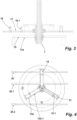
- Figure 1 shows an industrial mixing machine 1.
- the industrial mixing machine 1 has a frame 2 comprising a first support 3 and a second support 4, which are connected in their upper areas by a mixing crossbar 5.
- the mixing crossbar 5 has a mixing drive 6, with which a mixing head 7 mounted in Figure 1 not visible because it is hidden.
- the mixing tool is driven.
- the mixing machine 1 has a container entrance 8 located under the mixing crossbeam 5.
- a mixing container (not shown here), in which the mixture to be mixed is located, is driven and positioned by a worker into the container entrance 8.
- Such a mixing container driven into the container entrance 8 is a prepared mixing container, ready to be picked up by the mixing machine 1 in order to mix its contents.
- the mixing machine 1 To pick up the mixing container, the mixing machine 1 has two laterally arranged spindle drives 9, 9.1 with lifting plates 10, 10.1 connected to them, which grip under an outwardly projecting flange plate of the mixing container, so that the mixing container can be brought to the mixing head 7 and thus to the mixing tool 1 by means of the spindle drives 9, 9.1.
- the container entrance 8 has lateral guide rods 11, 11.1 mounted near the ground.
- the mixing cross member 5 is tilted about its longitudinal axis, mounted on the supports 3, 4, so that the mixing container is brought into an overhead position.
- the mixing drive 6 is activated, which mixes the mixture in the mixing container by means of a mixing tool mounted on the mixing head 7, not shown in detail here.
- the mixing machine 1 has a mixing tool storage area 12 on one of its side supports 4, in which mixing tools 13, 13.1 are stored at mixing tool storage locations 14, 14.1 when they are not mounted on the mixing head 7.
- the mixing tool storage locations 14, 14.1 have receiving pins 15, 15.1 with which the mixing tools 13, 13.1 are held at their pivot point.
- the mixing machine 1 is provided with a detection device to determine which mixing tool is currently mounted on the mixing head 7. To determine the mixing tool mounted on the mixing head 7, this can be determined directly on the mixing head 7 or it can be determined which mixing tool storage location 14, 14.1 in the mixing tool storage area 12 is occupied in order to draw conclusions from this as to which of the mixing tools 13, 13.1 is mounted on the mixing head 7.
- the Figures 2 to 9 show various designs for detecting the mixing tool, either on the mixing head 7 or in the mixing tool storage area 12. It is understood that, even if in the following explanations the detection takes place on the mixing head 7 or in the mixing tool storage area 12, mutatis mutandis the detection can also take place in the other area. Identical parts are referred to below with the same reference numerals. Only with regard to differently designed mixing tools is a separate letter used as a suffix for each design in relation to the mixing tool.
- Figure 2 shows a possible detection of mixing tools 13, 13.1, stored at mixing tool storage locations 14, 14.1 of the Figure 1 shown mixing tool storage area 12.
- the two mixing tools 13, 13.1 are stored at their mixing tool storage locations 14, 14.1 in this embodiment essentially in one plane.
- the distance between the mounting pins 15, 15.1 is smaller than the radius of the larger mixing tool 13 and larger than the radius of the smaller mixing tool 13.1.
- the larger mixing tool 13 can only be placed on a mixing tool storage location 14 (here the upper one) if a wing of the mixing tool 13, 13.1 is forced to be aligned with the mounting pins 15, 15.1.
- proximity sensors 16, 16.1 are aligned with the mounting pins 15, 15.1.
- the proximity sensors 16, 16.1 are spaced so far from the receiving pins 15, 15.1 that they are directed towards the end area of the respective mixing tool 13, 13.1. If the smaller mixing tool 14.1 were to be placed on the mixing tool storage location 14 actually assigned to the larger mixing tool 13, the proximity sensor 16 would not be triggered. In this way, mixing up the mixing tools 13, 13.1 with regard to their mixing tool storage locations 14, 14.1 is prevented by a clever combination of geometric factors and the arrangement of the sensors. This optimized design is a particularly cost-effective design that requires few additional parts.
- the proximity sensors 16, 16.1 can also - advantageously - be assigned to the detection device of the mixing machine 1, wherein the proximity sensors 16, 16.1 determine whether the respective mixing tool 13, 13.1 is held at its mixing tool storage location 14, 14.1.
- FIG 3 shows the mixing machine 1 in a different configuration:
- the mixing tool 13a is mounted on the mixing head 7, or on the shaft of the mixing drive 6.
- Ultrasonic sensors 18, 18.1 are arranged in the flange plate 17 associated with the mixing head 7. These ultrasonic sensors 18, 18.1 are arranged on different diameters in relation to the shaft of the mixing drive 6, thus in relation to the pivot point of the mixing tool 13a mounted on the mixing head 7; a first ultrasonic sensor 18 is aligned with a further diameter as a second ultrasonic sensor 18.1.
- the ultrasonic sensors measure starting from the flange plate 17 pointing downwards in the direction of the mixing tool 13a.
- the mixing tool 13a is rotated so that a wing 19 is arranged below the ultrasonic sensors 18, 18.1 and can be measured by them.
- the mixing tool 13a To rotate the mixing tool 13a, this can be done manually by a worker; it is also possible for the mixing tool 13a to be driven by the mixing drive 6 or a separate drive, which is not shown in detail here.
- the diameter of the mixing tool 13a By means of a corresponding signal from the ultrasonic sensors 18, 18.1, which report whether a mixing tool 13a is detected among them, the diameter of the mixing tool 13a can be determined in order to check whether the mounted mixing tool 13a fits the mixing container provided.
- FIG. 4 Another design shows Figure 4 .
- two mixing tools 13b, 13b.1 are shown arranged one above the other.
- the first mixing tool 13b has a larger diameter than the second mixing tool 13b.1.
- three light barriers 20, 20.1, 20.2 are arranged in this embodiment in such a way that their measuring direction is aligned with the diameter of the two mixing tools 13b, 13b.1.
- the measuring directions are aligned parallel and have different distances from the pivot point 21 of the mixing tools 13b, 13b.1.
- the measuring directions of two light barriers 20, 20.2 are aligned opposite each other with respect to the pivot point 21.
- the two outer light barriers 20, 20.2 are at such a distance from the pivot point 21 that they never detect the smaller mixing tool 13b.1.
- Figure 5 shows, in a further embodiment, the detection of mixing tools using magnets.
- Different mixing tools 13c, 13c.1, 13c.2 have magnets 22, 22.1, 22.2, 22.3, 22.4, 22.5 at different positions - resulting in a clear combination of distances.
- the detection device has Hall sensors 23, 23.1 arranged here on the flange plate 17, which are directed at the magnets 22.3, 22.5 of the mixing tool 13c.2 mounted here as an example.
- the individual magnets 22, 22.1, 22.2, 22.3, 22.4, 22.5 are detected one after the other depending on the angle of rotation of the mixing tool 13c.2. From this, it can be deduced which mixing tool 13c.2 is involved so that it can be determined whether the mounted mixing tool 13c.2 fits the mixing container provided.
- FIG. 6 shows a further embodiment based on RFID technology.
- the flange plate 17 has an RFID sensor 24; the mixing tool 13d has an RFID chip 25. If the mixing tool 13d is mounted on the mixing head 7, a sealing ring 26, for example, presses against the flange plate 17 in order to seal the area in which the RFID chip 25 is arranged and in particular to keep it free of dust. By reading the RFID chip using the RFID sensor, the corresponding information can be read out in order to draw conclusions about the mounted mixing tool 13d.
- FIG 7 shows a further embodiment, wherein the detection of the mixing tool 13e mounted here on the mixing head 7 is carried out by a detection contour inside the mixing tool 13e (in an enlarged view in Figure 7a with reference number 27).
- the detection contour 27 in this case is a Recess.
- Touch sensors 29, 29.1, 29.2 are arranged in the key 28 of the drive shaft of the mixing drive 6. While the two upper touch sensors 29, 29.1 detect the recess 27 of the detection contour, the lowest touch sensor 29.2 detects an elevation of the detection contour in this case. This is used to identify the mixing tool 13e.
- Figure 8 shows an embodiment in which mixing tools 13f, 13f.1 (which are again shown simultaneously in this view) are detected by a scanner 30.
- the scanner 30 scans an area 31 and determines the corresponding diameter of the mixing tool in this area (here marked with reference numerals 32, 32.1).
- a side view of this configuration shows Figure 8a . It can be seen that the scanner 30 is at the same height as the mixing tools 13f, 13f.1, so that the scanner 30 can detect the mixing tools 13f, 13f.1.
- Figure 9 shows a configuration in which the mixing tool 13g mounted on the mixing head 7 is recognized by means of a camera system 33 via optical imaging methods.
- the mixing tool 13-13g which is mounted on the mixing head 7, is recognized - for example according to one of the embodiments described above - it is determined whether the mixing tool 13-13g fits the provided mixing container, which in this embodiment is moved into the container entrance 8. In particular, it is checked whether the diameter of the mixing tool 13-13g fits the container opening, so that contact between the mixing tool 13-13g and the mixing container is avoided. If the test is positive, i.e. the mounted mixing tool 13-13g fits the provided mixing container, the mixing container is moved towards the flange plate 17 so that the mixing tool 13-13g dips into the container opening. The mixing process then begins.
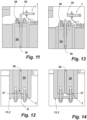
- FIG 10 shows a mixing tool 13.2 mounted on a connection of the mixing machine 1, namely on the drive shaft 34.
- the mixing tool 13.2 has a detection section E in the form of a pin, which is the detection section E protrudes from the material surrounding the detection section E.
- the detection section E penetrates the drive shaft 34, which is designed here as a hollow shaft.
- the drive shaft 34 is mounted radially on the outside on a bearing arrangement 35.
- a rod 36 designed here as a rod, is inserted into the center of the drive shaft 34.
- the rod 36 penetrates the drive shaft 34.
- the rod 36 is at least partially enclosed in the radial direction by the drive shaft 34 and is thus mounted and can be moved in translation.
- the detection section E acts on a distal end of the rod 36, on the so-called sensor section 37, here formed by the end face of the rod.
- the rod By mounting the mixing tool 13.2 on the drive shaft 34, the rod is displaced translationally, here in a vertical upward direction, into another position. The displacement takes place against the spring force of a return spring 38, against which the rod 36 is mounted in the displacement direction relative to the mixing machine 1.
- the measuring device 39 designed as a proximity sensor, the detection device of the mixing machine 1 connected to the measuring device 39 detects whether the rod 36, or the measuring section 40, i.e.
- the distal end of the rod 36 opposite the sensor section 37 protrudes from the drive shaft 34 to such an extent that it can be concluded that the detection section E of the mixing tool 13.2 acts on the sensor section 37 of the rod 36. In this way, it can be concluded that the mixing tool 13.2 is mounted.
- FIGS 11 to 14 show detailed pictures of two different mixing tools: a first mixing tool 13.2 ( Figures 11 and 12 ) and a different second mixing tool 13.3 (Figures 13 and 14), each connected to the mixing machine 1. Shown in the Figures 11 and 13 the upper part of the mixing machine 1 (which is also in Figure 10 shown), in the Figures 12 and 14 the lower area, namely the area to which the mixing tool 13.2, 13.3 is connected.
- the two mixing tools 13.2 and 13.3 differ in their maximum diameter. Accordingly, they also differ in their detection section: While the first mixing tool 13.2 has a detection section E, the second mixing tool 13.3 does not. Accordingly, the rod 36 is displaced translationally through the detection section E of the first mixing tool 13.2 in the drive shaft 34 (see Figure 11 ), while it is not moved with the second mixing tool 13.3 (see Figure 13 ). If the first mixing tool 13.2 is mounted, the measuring device 39 (designed as a proximity sensor) detects that the rod 36 is brought close to it; this is precisely what is required in the design of the Figures 13 and 14 (other mixing tool 13.3 mounted) is not the case. In this way, the two mixing tools 13.2 and 13.3 can be distinguished.
- the drive shaft 34 with the mixing tool 13.2, 13.3 mounted thereon can be easily set in a rotary motion without the measuring device 39 being affected in its measurement or additional electrical contacts, for example via slip ring contacts, having to be led from the connection of the mixing tool 13.2, 13.3.
- the rod 36 centrally in the center of the drive shaft 34, this also does not act as an eccentric imbalance that negatively affects the smooth operation of the mixing tool 13.2, 13.3.
Landscapes
- Chemical & Material Sciences (AREA)
- Chemical Kinetics & Catalysis (AREA)
- Engineering & Computer Science (AREA)
- General Engineering & Computer Science (AREA)
- Software Systems (AREA)
- Accessories For Mixers (AREA)
- Processing And Handling Of Plastics And Other Materials For Molding In General (AREA)
Claims (16)
- Mélangeur industriel (1) pour mélanger un matériau mixte dans des conteneurs-mélangeurs ouverts du côté raccordement, se différenciant les uns des autres par au moins une caractéristique de leur conception, chaque conteneur-mélangeur étant raccordable à la tête mélangeuse du mélangeur (1) afin de mélanger le matériau mixte qu'il contient et au moins deux outils mélangeurs (13, 13.1, 13a, 13b, 13b.1, 13c, 13c.1, 13c.2, 13d, 13e, 13f, 13f.1, 13g), se différenciant l'un de l'autre par au moins une caractéristique de leur conception pouvant étant montés sur une tête mélangeuse (7) du mélangeur (1), caractérisé en ce que le mélangeur (1) comporte :- un dispositif de reconnaissance configuré pour identifier si l'outil mélangeur (13, 13.1, 13a, 13b, 13b.1, 13c, 13c.1, 13c.2, 13d, 13e, 13f, 13f.1, 13g) actuellement monté sur la tête mélangeuse (7) est compatible avec le conteneur-mélangeur, lequel contient le matériau mixte à mélanger et doit être raccordé à la tête mélangeuse et- un équipement de sécurité en communication avec le dispositif de reconnaissance, qui empêche l'association de l'outil mélangeur (13, 13.1, 13a, 13b, 13b.1, 13c, 13c.1, 13c.2, 13d, 13e, 13f, 13f.1, 13g) avec l'ouverture du conteneur-mélangeur dès lors que le dispositif de reconnaissance détecte que l'outil mélangeur (13, 13.1, 13a, 13b, 13b.1, 13c, 13c.1, 13c.2, 13d, 13e, 13f, 13f.1, 13g) monté sur la tête mélangeuse (7) n'est pas compatible avec le conteneur-mélangeur.
- Mélangeur industriel selon la revendication 1, caractérisé en ce que le dispositif de reconnaissance est configuré pour reconnaître quel est l'outil mélangeur (13, 13.1, 13c, 13c.1, 13c.2, 13d, 13e, 13g) monté sur la tête mélangeuse (7).
- Mélangeur industriel selon l'une des revendications 1 ou 2, caractérisé en ce que le dispositif de reconnaissance dispose de capteurs et qu'un outil mélangeur (13, 13.1, 13a, 13b, 13b.1, 13c, 13c.1, 13c.2, 13d, 13e, 13f, 13f.1, 13g) dispose d'une identification distincte d'un autre outil mélangeur (13, 13.1, 13a, 13b, 13b.1, 13c, 13c.1, 13c.2, 13d, 13e, 13f, 13f.1, 13g), détectable par les capteurs.
- Mélangeur industriel selon l'une des revendications 1 à 3, caractérisé en ce que l'identification est un contour reconnaissable (27).
- Mélangeur industriel selon l'une des revendications 1 à 4, caractérisé en ce qu'une clavette (18) est disposée sur la tête mélangeuse (7) ou respectivement sur l'arbre entraînant l'outil mélangeur (13e), laquelle clavette (18), afin de transmettre un couple de l'arbre sur l'outil mélangeur (13e), butte par complémentarité de forme dans le sens périphérique quand elle est montée, sur une rainure à clavette située côté outil mélangeur et laquelle clavette (18) dispose d'au moins un capteur de contours (19, 19.1, 19.2).
- Mélangeur industriel selon l'une des revendications 1 à 5, caractérisé en ce que le dispositif de reconnaissance est configuré pour exploiter des signaux d'angle de rotation convertis de l'outil mélangeur.
- Mélangeur industriel selon l'une des revendications 3 à 6, caractérisé en ce que l'identification porte sur le diamètre (32, 32.1) de l'outil mélangeur (13, 13.1, 13a, 13b, 13b.1, 13f, 13f.1, 13g).
- Mélangeur industriel selon la revendication 7, caractérisé en ce que le dispositif de reconnaissance dispose d'au moins une barrière lumineuse (20, 20.1, 20.2) placée de manière excentrique par rapport au point de rotation (21) de l'outil mélangeur (13b, 13b.1) et dont l'orientation de la mesure est ajustée pour rester dans le diamètre de l'outil mélangeur (13b, 13b.1).
- Mélangeur industriel selon la revendication 8, caractérisé en ce qu'au moins deux barrières lumineuses (20, 20.1, 20.2) sont disposées de manière excentrique, orientées parallèlement par rapport au point de rotation (21) de l'outil mélangeur (13b, 13b.1), à distance l'une de l'autre et à une distance différente du point de rotation (21), la première barrière lumineuse (20) mesurant un premier diamètre d'outil mélangeur et la seconde barrière lumineuse (20.1), un second diamètre d'outil mélangeur différent du premier.
- Mélangeur industriel selon l'une des revendications 1 à 9, caractérisé en ce que les capteurs sont des capteurs à palpeur (29, 29.1, 29.2), des capteurs inductifs ou des capteurs à ultrasons (18, 18.1).
- Mélangeur industriel selon l'une des revendications 1 à 10, caractérisé en ce que le capteur du dispositif de reconnaissance est disposé dans la zone de la tête mélangeuse (7) sur le mélangeur (1).
- Mélangeur industriel selon l'une des revendications 1 à 11, caractérisé en ce que le mélangeur (1) dispose d'une zone de dépose (12) d'outil mélangeur, contre laquelle est entreposé au moins un outil mélangeur (13, 13.1) qui, pendant l'utilisation du mélangeur (1), n'est pas monté sur la tête mélangeuse (7) et que le dispositif de reconnaissance est configuré pour surveiller la zone de dépose (12) d'outil mélangeur, afin de déduire de l'occupation de la zone de dépose (12) d'outil mélangeur, quel est l'outil mélangeur (13, 13.1) monté sur la tête mélangeuse (7).
- Mélangeur industriel selon la revendication 12, caractérisé en ce que la zone de dépose (12) d'outil mélangeur dispose d'emplacements (14, 14.1) de dépose d'outils mélangeurs, lesquels sont précisément prévus pour un outil mélangeur (13, 13.1) bien défini.
- Mélangeur industriel selon la revendication 12 ou 13, caractérisé en ce que le dispositif de reconnaissance dispose d'un capteur de proximité (16, 16.1), qui est configuré pour détecter si une partie d'un outil mélangeur (13, 13.1) est à proximité.
- Procédé à réaliser avec un mélangeur industriel comportant les étapes suivantes :- Détection de l'outil mélangeur actuellement monté sur la tête mélangeuse,- Détection du conteneur mis à disposition,- Vérification si l'outil mélangeur détecté est compatible avec le conteneur mis à disposition et- si l'outil mélangeur détecté n'est pas compatible avec le conteneur mis à disposition, activation d'un dispositif de sécurité afin d'empêcher l'association de l'outil mélangeur avec l'ouverture du conteneur.
- Mélangeur industriel selon l'une des revendications 1 à 14, lequel mélangeur industriel exécute le procédé selon la revendication 15.
Priority Applications (2)
| Application Number | Priority Date | Filing Date | Title |
|---|---|---|---|
| CN202211384027.6A CN116196790A (zh) | 2021-11-30 | 2022-11-07 | 工业的混合机器 |
| US17/993,705 US12582950B2 (en) | 2021-11-30 | 2022-11-23 | Industrial mixing machine |
Applications Claiming Priority (3)
| Application Number | Priority Date | Filing Date | Title |
|---|---|---|---|
| DE202021106516.8U DE202021106516U1 (de) | 2021-11-30 | 2021-11-30 | Industrielle Mischmaschine |
| DE102021131517.4A DE102021131517A1 (de) | 2021-12-01 | 2021-12-01 | Industrielle Mischmaschine |
| DE202022100646.6U DE202022100646U1 (de) | 2022-02-04 | 2022-02-04 | Industrielle Mischmaschine |
Publications (3)
| Publication Number | Publication Date |
|---|---|
| EP4190436A1 EP4190436A1 (fr) | 2023-06-07 |
| EP4190436C0 EP4190436C0 (fr) | 2024-09-04 |
| EP4190436B1 true EP4190436B1 (fr) | 2024-09-04 |
Family
ID=83903171
Family Applications (1)
| Application Number | Title | Priority Date | Filing Date |
|---|---|---|---|
| EP22202208.9A Active EP4190436B1 (fr) | 2021-11-30 | 2022-10-18 | Mélangeur industriel |
Country Status (4)
| Country | Link |
|---|---|
| US (1) | US12582950B2 (fr) |
| EP (1) | EP4190436B1 (fr) |
| CN (1) | CN116196790A (fr) |
| ES (1) | ES2995973T3 (fr) |
Families Citing this family (1)
| Publication number | Priority date | Publication date | Assignee | Title |
|---|---|---|---|---|
| USD1006843S1 (en) * | 2022-06-21 | 2023-12-05 | Ekato Systems Gmbh | Industrial mixer |
Family Cites Families (22)
| Publication number | Priority date | Publication date | Assignee | Title |
|---|---|---|---|---|
| DE3543913A1 (de) | 1985-12-12 | 1987-06-19 | Herfeld Friedrich W | Mischvorrichtung |
| DE4422086C1 (de) * | 1994-06-24 | 1995-09-21 | Braun Ag | Küchenmaschine |
| KR101525372B1 (ko) * | 2005-06-28 | 2015-06-09 | 스트리커 코포레이션 | 슬립 모드 또는 활성 모드로 동작할 수 있는 동력이 있는 수술 도구용 제어 어셈블리 |
| DE102005040525A1 (de) * | 2005-08-26 | 2007-03-01 | BSH Bosch und Siemens Hausgeräte GmbH | Küchengerät mit Sicherheitssystem und Verfahren zum Betreiben eines Küchengeräts |
| DE202009001937U1 (de) | 2009-03-04 | 2009-04-30 | Mixaco Dr. Herfeld Gmbh & Co. Kg | Mischmaschine |
| DE202009004866U1 (de) | 2009-05-26 | 2010-10-14 | Dr. Herfeld Gmbh & Co. Kg | Kühlmischer |
| DE202013103591U1 (de) | 2013-08-09 | 2013-08-27 | Dr. Herfeld Gmbh & Co Kg | Inliner zum Auskleiden eines Mischcontainers sowie Anordnung umfassend einen Mischcontainer sowie einen darin eingesetzten Inliner |
| DE102013111158B3 (de) * | 2013-10-09 | 2014-11-13 | Dr. Herfeld Gmbh & Co. Kg | Verfahren zum Mischen eines Mischgutes innerhalb eines geschlossenen Mischraumes sowie industrieller Mischer |
| DE202014101787U1 (de) | 2014-04-15 | 2014-04-30 | Dr. Herfeld Gmbh & Co. Kg | Mischmaschine |
| US10624499B2 (en) * | 2014-07-30 | 2020-04-21 | North American Robotics Corporation | Systems and methods for pressure control in automated blending devices |
| DE202015103285U1 (de) | 2015-06-23 | 2016-09-26 | Dr. Herfeld Gmbh & Co. Kg | Mischcontainer sowie Entleerstation für einen solchen Mischcontainer |
| DE202015103284U1 (de) | 2015-06-23 | 2016-09-26 | Dr. Herfeld Gmbh & Co Kg | Mischmaschine sowie Inliner dafür |
| WO2017004661A1 (fr) * | 2015-07-08 | 2017-01-12 | Breville Pty Limited | Appareil de cuisine pour la détection de propriétés d'aliments et de boissons |
| US10702839B2 (en) * | 2016-02-29 | 2020-07-07 | Nik of Time, Inc. | Precision dispensing and mixing apparatus |
| DE102016012872A1 (de) * | 2016-10-12 | 2018-04-12 | Mti Mischtechnik International Gmbh | Verfahren und Vorrichtung zum Mischen von pulver- oder granulatförmigen Stoffen |
| US11039715B2 (en) * | 2017-07-05 | 2021-06-22 | Illinois Tool Works Inc. | Food processing machine adaptive to food load |
| EP3530348B1 (fr) | 2018-02-20 | 2021-09-08 | Dr. HERFELD GmbH & Co. KG | Machine à mélanger |
| US11224848B2 (en) | 2018-02-20 | 2022-01-18 | Dr. Herfeld Gmbh & Co. Kg | Mixing machine |
| US12178361B2 (en) * | 2018-12-04 | 2024-12-31 | Vita-Mix Management Corporation | Dynamic power control of torque in motor |
| DE202019104870U1 (de) | 2019-09-04 | 2019-09-18 | Dr. Herfeld Gmbh & Co. Kg | Mischmaschine |
| KR102326488B1 (ko) * | 2019-12-16 | 2021-11-17 | 대구가톨릭대학교산학협력단 | 용액의 점도를 측정하는 교반 장치 및 점도 측정 방법 |
| DE202021101371U1 (de) | 2021-03-18 | 2021-03-29 | Dr. Herfeld Gmbh & Co. Kg | Flanschdichtung sowie damit ausgerüsteter Mischcontainer und industrielle Mischmaschine |
-
2022
- 2022-10-18 EP EP22202208.9A patent/EP4190436B1/fr active Active
- 2022-10-18 ES ES22202208T patent/ES2995973T3/es active Active
- 2022-11-07 CN CN202211384027.6A patent/CN116196790A/zh active Pending
- 2022-11-23 US US17/993,705 patent/US12582950B2/en active Active
Also Published As
| Publication number | Publication date |
|---|---|
| ES2995973T3 (en) | 2025-02-11 |
| EP4190436C0 (fr) | 2024-09-04 |
| US20230166225A1 (en) | 2023-06-01 |
| EP4190436A1 (fr) | 2023-06-07 |
| US12582950B2 (en) | 2026-03-24 |
| CN116196790A (zh) | 2023-06-02 |
Similar Documents
| Publication | Publication Date | Title |
|---|---|---|
| EP2569592B1 (fr) | Sonde pour un appareil de mesure de coordonnées servant à la détermination de coordonnées dans l'espace sur un objet à mesurer | |
| DE69003149T2 (de) | Tastkopf. | |
| EP2394134B1 (fr) | Système palpeur pour un appareil de mesure de coordonnées | |
| DE3527546C1 (de) | Vorrichtung zum Verbinden einer Positionsmesseinrichtung mit zwei relativ zueinander beweglichen Objekten | |
| DE10140103C1 (de) | Zweiflanken-Wälzprüfgerät | |
| EP1660393A1 (fr) | Dispositif de controle d'une installation de convoyage | |
| EP4190436B1 (fr) | Mélangeur industriel | |
| EP3554708B1 (fr) | Procédé servant à identifier le type d'une unité piston-cylindre pouvant être remplacée pour un distributeur | |
| EP0952465A2 (fr) | Dispositif de marquage | |
| EP1394503A2 (fr) | Dispositif pour mesurer la profondeur d'un profil | |
| DE102019102212A1 (de) | Reifengreifer | |
| DE69316310T2 (de) | Aufhängungsvorrichtung einer Sonde zur Detektion und Lokalisation von eventuellen Fehlern im Inneren einer Bohrung | |
| DE19617023C1 (de) | Oberflächenmeßgerät | |
| EP3882505B1 (fr) | Dispositif de surveillance et procédé de fonctionnement d'un dispositif de surveillance | |
| WO2017001676A1 (fr) | Système de pipetage muni d'un dispositif de traitement d'images | |
| EP3062113B1 (fr) | Surveillance de rotation | |
| DE102021131517A1 (de) | Industrielle Mischmaschine | |
| DE202021106516U1 (de) | Industrielle Mischmaschine | |
| DE202022100646U1 (de) | Industrielle Mischmaschine | |
| DE3032520A1 (de) | Anordnung zur kontrolle der einsatzdauer von zylindrischen behaeltnissen | |
| DE68912281T2 (de) | Verfahren und Vorrichtung zum Wahrnehmen des Standes eines Ventils. | |
| EP2358622B1 (fr) | Boîtier pour une tête de mesure de nettoyeur de fil | |
| EP4146409A2 (fr) | Installation de contrôle conçue pour une pluralité de corps distincts à contrôler | |
| DE19961886B4 (de) | Lenkeinrichtung | |
| WO2002054009A1 (fr) | Coordinatometre ayant une tete palpeuse dotee d'un element de protection contre les projections |
Legal Events
| Date | Code | Title | Description |
|---|---|---|---|
| PUAI | Public reference made under article 153(3) epc to a published international application that has entered the european phase |
Free format text: ORIGINAL CODE: 0009012 |
|
| STAA | Information on the status of an ep patent application or granted ep patent |
Free format text: STATUS: THE APPLICATION HAS BEEN PUBLISHED |
|
| STAA | Information on the status of an ep patent application or granted ep patent |
Free format text: STATUS: REQUEST FOR EXAMINATION WAS MADE |
|
| AK | Designated contracting states |
Kind code of ref document: A1 Designated state(s): AL AT BE BG CH CY CZ DE DK EE ES FI FR GB GR HR HU IE IS IT LI LT LU LV MC ME MK MT NL NO PL PT RO RS SE SI SK SM TR |
|
| 17P | Request for examination filed |
Effective date: 20230516 |
|
| P01 | Opt-out of the competence of the unified patent court (upc) registered |
Effective date: 20230619 |
|
| RBV | Designated contracting states (corrected) |
Designated state(s): AL AT BE BG CH CY CZ DE DK EE ES FI FR GB GR HR HU IE IS IT LI LT LU LV MC ME MK MT NL NO PL PT RO RS SE SI SK SM TR |
|
| GRAP | Despatch of communication of intention to grant a patent |
Free format text: ORIGINAL CODE: EPIDOSNIGR1 |
|
| STAA | Information on the status of an ep patent application or granted ep patent |
Free format text: STATUS: GRANT OF PATENT IS INTENDED |
|
| GRAJ | Information related to disapproval of communication of intention to grant by the applicant or resumption of examination proceedings by the epo deleted |
Free format text: ORIGINAL CODE: EPIDOSDIGR1 |
|
| STAA | Information on the status of an ep patent application or granted ep patent |
Free format text: STATUS: REQUEST FOR EXAMINATION WAS MADE |
|
| INTG | Intention to grant announced |
Effective date: 20231220 |
|
| INTC | Intention to grant announced (deleted) | ||
| GRAP | Despatch of communication of intention to grant a patent |
Free format text: ORIGINAL CODE: EPIDOSNIGR1 |
|
| STAA | Information on the status of an ep patent application or granted ep patent |
Free format text: STATUS: GRANT OF PATENT IS INTENDED |
|
| INTG | Intention to grant announced |
Effective date: 20240227 |
|
| GRAS | Grant fee paid |
Free format text: ORIGINAL CODE: EPIDOSNIGR3 |
|
| GRAA | (expected) grant |
Free format text: ORIGINAL CODE: 0009210 |
|
| STAA | Information on the status of an ep patent application or granted ep patent |
Free format text: STATUS: THE PATENT HAS BEEN GRANTED |
|
| AK | Designated contracting states |
Kind code of ref document: B1 Designated state(s): AL AT BE BG CH CY CZ DE DK EE ES FI FR GB GR HR HU IE IS IT LI LT LU LV MC ME MK MT NL NO PL PT RO RS SE SI SK SM TR |
|
| REG | Reference to a national code |
Ref country code: GB Ref legal event code: FG4D Free format text: NOT ENGLISH |
|
| REG | Reference to a national code |
Ref country code: CH Ref legal event code: EP |
|
| REG | Reference to a national code |
Ref country code: IE Ref legal event code: FG4D Free format text: LANGUAGE OF EP DOCUMENT: GERMAN |
|
| REG | Reference to a national code |
Ref country code: DE Ref legal event code: R096 Ref document number: 502022001610 Country of ref document: DE |
|
| U01 | Request for unitary effect filed |
Effective date: 20240927 |
|
| P04 | Withdrawal of opt-out of the competence of the unified patent court (upc) registered |
Free format text: CASE NUMBER: APP_57499/2024 Effective date: 20241021 |
|
| U07 | Unitary effect registered |
Designated state(s): AT BE BG DE DK EE FI FR IT LT LU LV MT NL PT RO SE SI Effective date: 20241024 |
|
| U20 | Renewal fee for the european patent with unitary effect paid |
Year of fee payment: 3 Effective date: 20241002 |
|
| PG25 | Lapsed in a contracting state [announced via postgrant information from national office to epo] |
Ref country code: NO Free format text: LAPSE BECAUSE OF FAILURE TO SUBMIT A TRANSLATION OF THE DESCRIPTION OR TO PAY THE FEE WITHIN THE PRESCRIBED TIME-LIMIT Effective date: 20241204 |
|
| PG25 | Lapsed in a contracting state [announced via postgrant information from national office to epo] |
Ref country code: GR Free format text: LAPSE BECAUSE OF FAILURE TO SUBMIT A TRANSLATION OF THE DESCRIPTION OR TO PAY THE FEE WITHIN THE PRESCRIBED TIME-LIMIT Effective date: 20241205 |
|
| PG25 | Lapsed in a contracting state [announced via postgrant information from national office to epo] |
Ref country code: HR Free format text: LAPSE BECAUSE OF FAILURE TO SUBMIT A TRANSLATION OF THE DESCRIPTION OR TO PAY THE FEE WITHIN THE PRESCRIBED TIME-LIMIT Effective date: 20240904 |
|
| PG25 | Lapsed in a contracting state [announced via postgrant information from national office to epo] |
Ref country code: RS Free format text: LAPSE BECAUSE OF FAILURE TO SUBMIT A TRANSLATION OF THE DESCRIPTION OR TO PAY THE FEE WITHIN THE PRESCRIBED TIME-LIMIT Effective date: 20241204 |
|
| PG25 | Lapsed in a contracting state [announced via postgrant information from national office to epo] |
Ref country code: RS Free format text: LAPSE BECAUSE OF FAILURE TO SUBMIT A TRANSLATION OF THE DESCRIPTION OR TO PAY THE FEE WITHIN THE PRESCRIBED TIME-LIMIT Effective date: 20241204 Ref country code: NO Free format text: LAPSE BECAUSE OF FAILURE TO SUBMIT A TRANSLATION OF THE DESCRIPTION OR TO PAY THE FEE WITHIN THE PRESCRIBED TIME-LIMIT Effective date: 20241204 Ref country code: HR Free format text: LAPSE BECAUSE OF FAILURE TO SUBMIT A TRANSLATION OF THE DESCRIPTION OR TO PAY THE FEE WITHIN THE PRESCRIBED TIME-LIMIT Effective date: 20240904 Ref country code: GR Free format text: LAPSE BECAUSE OF FAILURE TO SUBMIT A TRANSLATION OF THE DESCRIPTION OR TO PAY THE FEE WITHIN THE PRESCRIBED TIME-LIMIT Effective date: 20241205 |
|
| REG | Reference to a national code |
Ref country code: ES Ref legal event code: FG2A Ref document number: 2995973 Country of ref document: ES Kind code of ref document: T3 Effective date: 20250211 |
|
| PG25 | Lapsed in a contracting state [announced via postgrant information from national office to epo] |
Ref country code: IS Free format text: LAPSE BECAUSE OF FAILURE TO SUBMIT A TRANSLATION OF THE DESCRIPTION OR TO PAY THE FEE WITHIN THE PRESCRIBED TIME-LIMIT Effective date: 20250104 |
|
| PG25 | Lapsed in a contracting state [announced via postgrant information from national office to epo] |
Ref country code: SM Free format text: LAPSE BECAUSE OF FAILURE TO SUBMIT A TRANSLATION OF THE DESCRIPTION OR TO PAY THE FEE WITHIN THE PRESCRIBED TIME-LIMIT Effective date: 20240904 |
|
| PG25 | Lapsed in a contracting state [announced via postgrant information from national office to epo] |
Ref country code: CZ Free format text: LAPSE BECAUSE OF FAILURE TO SUBMIT A TRANSLATION OF THE DESCRIPTION OR TO PAY THE FEE WITHIN THE PRESCRIBED TIME-LIMIT Effective date: 20240904 Ref country code: PL Free format text: LAPSE BECAUSE OF FAILURE TO SUBMIT A TRANSLATION OF THE DESCRIPTION OR TO PAY THE FEE WITHIN THE PRESCRIBED TIME-LIMIT Effective date: 20240904 |
|
| PG25 | Lapsed in a contracting state [announced via postgrant information from national office to epo] |
Ref country code: SK Free format text: LAPSE BECAUSE OF FAILURE TO SUBMIT A TRANSLATION OF THE DESCRIPTION OR TO PAY THE FEE WITHIN THE PRESCRIBED TIME-LIMIT Effective date: 20240904 |
|
| PG25 | Lapsed in a contracting state [announced via postgrant information from national office to epo] |
Ref country code: MC Free format text: LAPSE BECAUSE OF FAILURE TO SUBMIT A TRANSLATION OF THE DESCRIPTION OR TO PAY THE FEE WITHIN THE PRESCRIBED TIME-LIMIT Effective date: 20240904 |
|
| PLBE | No opposition filed within time limit |
Free format text: ORIGINAL CODE: 0009261 |
|
| STAA | Information on the status of an ep patent application or granted ep patent |
Free format text: STATUS: NO OPPOSITION FILED WITHIN TIME LIMIT |
|
| 26N | No opposition filed |
Effective date: 20250605 |
|
| U20 | Renewal fee for the european patent with unitary effect paid |
Year of fee payment: 4 Effective date: 20250909 |
|
| PG25 | Lapsed in a contracting state [announced via postgrant information from national office to epo] |
Ref country code: IE Free format text: LAPSE BECAUSE OF NON-PAYMENT OF DUE FEES Effective date: 20241018 |
|
| PGFP | Annual fee paid to national office [announced via postgrant information from national office to epo] |
Ref country code: TR Payment date: 20251015 Year of fee payment: 4 |
|
| PG25 | Lapsed in a contracting state [announced via postgrant information from national office to epo] |
Ref country code: CY Free format text: LAPSE BECAUSE OF FAILURE TO SUBMIT A TRANSLATION OF THE DESCRIPTION OR TO PAY THE FEE WITHIN THE PRESCRIBED TIME-LIMIT; INVALID AB INITIO Effective date: 20221018 |
|
| PGFP | Annual fee paid to national office [announced via postgrant information from national office to epo] |
Ref country code: ES Payment date: 20251114 Year of fee payment: 4 |
|
| PG25 | Lapsed in a contracting state [announced via postgrant information from national office to epo] |
Ref country code: HU Free format text: LAPSE BECAUSE OF FAILURE TO SUBMIT A TRANSLATION OF THE DESCRIPTION OR TO PAY THE FEE WITHIN THE PRESCRIBED TIME-LIMIT; INVALID AB INITIO Effective date: 20221018 |