EP4198238A1 - Amortisseur pour une butée destinée au stockage mobile d'un élément pivotant ou d'un élément d'extraction - Google Patents
Amortisseur pour une butée destinée au stockage mobile d'un élément pivotant ou d'un élément d'extraction Download PDFInfo
- Publication number
- EP4198238A1 EP4198238A1 EP21214294.7A EP21214294A EP4198238A1 EP 4198238 A1 EP4198238 A1 EP 4198238A1 EP 21214294 A EP21214294 A EP 21214294A EP 4198238 A1 EP4198238 A1 EP 4198238A1
- Authority
- EP
- European Patent Office
- Prior art keywords
- piston
- damper
- section
- fluid chamber
- sealing element
- Prior art date
- Legal status (The legal status is an assumption and is not a legal conclusion. Google has not performed a legal analysis and makes no representation as to the accuracy of the status listed.)
- Granted
Links
Images



Classifications
-
- E—FIXED CONSTRUCTIONS
- E05—LOCKS; KEYS; WINDOW OR DOOR FITTINGS; SAFES
- E05F—DEVICES FOR MOVING WINGS INTO OPEN OR CLOSED POSITION; CHECKS FOR WINGS; WING FITTINGS NOT OTHERWISE PROVIDED FOR, CONCERNED WITH THE FUNCTIONING OF THE WING
- E05F5/00—Braking devices, e.g. checks; Stops; Buffers
- E05F5/02—Braking devices, e.g. checks; Stops; Buffers specially for preventing the slamming of swinging wings during final closing movement, e.g. jamb stops
-
- E—FIXED CONSTRUCTIONS
- E05—LOCKS; KEYS; WINDOW OR DOOR FITTINGS; SAFES
- E05F—DEVICES FOR MOVING WINGS INTO OPEN OR CLOSED POSITION; CHECKS FOR WINGS; WING FITTINGS NOT OTHERWISE PROVIDED FOR, CONCERNED WITH THE FUNCTIONING OF THE WING
- E05F5/00—Braking devices, e.g. checks; Stops; Buffers
- E05F5/006—Braking devices, e.g. checks; Stops; Buffers for hinges having a cup-shaped fixing part, e.g. for attachment to cabinets or furniture
-
- E—FIXED CONSTRUCTIONS
- E05—LOCKS; KEYS; WINDOW OR DOOR FITTINGS; SAFES
- E05F—DEVICES FOR MOVING WINGS INTO OPEN OR CLOSED POSITION; CHECKS FOR WINGS; WING FITTINGS NOT OTHERWISE PROVIDED FOR, CONCERNED WITH THE FUNCTIONING OF THE WING
- E05F5/00—Braking devices, e.g. checks; Stops; Buffers
- E05F5/06—Buffers or stops limiting opening of swinging wings, e.g. floor or wall stops
- E05F5/08—Buffers or stops limiting opening of swinging wings, e.g. floor or wall stops with springs
-
- E—FIXED CONSTRUCTIONS
- E05—LOCKS; KEYS; WINDOW OR DOOR FITTINGS; SAFES
- E05F—DEVICES FOR MOVING WINGS INTO OPEN OR CLOSED POSITION; CHECKS FOR WINGS; WING FITTINGS NOT OTHERWISE PROVIDED FOR, CONCERNED WITH THE FUNCTIONING OF THE WING
- E05F5/00—Braking devices, e.g. checks; Stops; Buffers
- E05F5/06—Buffers or stops limiting opening of swinging wings, e.g. floor or wall stops
- E05F5/10—Buffers or stops limiting opening of swinging wings, e.g. floor or wall stops with piston brakes
-
- E—FIXED CONSTRUCTIONS
- E05—LOCKS; KEYS; WINDOW OR DOOR FITTINGS; SAFES
- E05F—DEVICES FOR MOVING WINGS INTO OPEN OR CLOSED POSITION; CHECKS FOR WINGS; WING FITTINGS NOT OTHERWISE PROVIDED FOR, CONCERNED WITH THE FUNCTIONING OF THE WING
- E05F1/00—Closers or openers for wings, not otherwise provided for in this subclass
- E05F1/08—Closers or openers for wings, not otherwise provided for in this subclass spring-actuated, e.g. for horizontally sliding wings
- E05F1/10—Closers or openers for wings, not otherwise provided for in this subclass spring-actuated, e.g. for horizontally sliding wings for swinging wings, e.g. counterbalance
- E05F1/12—Mechanisms in the shape of hinges or pivots, operated by springs
- E05F1/1246—Mechanisms in the shape of hinges or pivots, operated by springs with a coil spring perpendicular to the pivot axis
- E05F1/1253—Mechanisms in the shape of hinges or pivots, operated by springs with a coil spring perpendicular to the pivot axis with a compression spring
- E05F1/1261—Mechanisms in the shape of hinges or pivots, operated by springs with a coil spring perpendicular to the pivot axis with a compression spring for counterbalancing
-
- E—FIXED CONSTRUCTIONS
- E05—LOCKS; KEYS; WINDOW OR DOOR FITTINGS; SAFES
- E05Y—INDEXING SCHEME ASSOCIATED WITH SUBCLASSES E05D AND E05F, RELATING TO CONSTRUCTION ELEMENTS, ELECTRIC CONTROL, POWER SUPPLY, POWER SIGNAL OR TRANSMISSION, USER INTERFACES, MOUNTING OR COUPLING, DETAILS, ACCESSORIES, AUXILIARY OPERATIONS NOT OTHERWISE PROVIDED FOR, APPLICATION THEREOF
- E05Y2201/00—Constructional elements; Accessories therefor
- E05Y2201/20—Brakes; Disengaging means; Holders; Stops; Valves; Accessories therefor
- E05Y2201/23—Actuation thereof
- E05Y2201/232—Actuation thereof by automatically acting means
- E05Y2201/236—Actuation thereof by automatically acting means using force or torque
-
- E—FIXED CONSTRUCTIONS
- E05—LOCKS; KEYS; WINDOW OR DOOR FITTINGS; SAFES
- E05Y—INDEXING SCHEME ASSOCIATED WITH SUBCLASSES E05D AND E05F, RELATING TO CONSTRUCTION ELEMENTS, ELECTRIC CONTROL, POWER SUPPLY, POWER SIGNAL OR TRANSMISSION, USER INTERFACES, MOUNTING OR COUPLING, DETAILS, ACCESSORIES, AUXILIARY OPERATIONS NOT OTHERWISE PROVIDED FOR, APPLICATION THEREOF
- E05Y2201/00—Constructional elements; Accessories therefor
- E05Y2201/20—Brakes; Disengaging means; Holders; Stops; Valves; Accessories therefor
- E05Y2201/252—Type of friction
- E05Y2201/254—Fluid or viscous friction
- E05Y2201/256—Fluid or viscous friction with pistons or vanes
-
- E—FIXED CONSTRUCTIONS
- E05—LOCKS; KEYS; WINDOW OR DOOR FITTINGS; SAFES
- E05Y—INDEXING SCHEME ASSOCIATED WITH SUBCLASSES E05D AND E05F, RELATING TO CONSTRUCTION ELEMENTS, ELECTRIC CONTROL, POWER SUPPLY, POWER SIGNAL OR TRANSMISSION, USER INTERFACES, MOUNTING OR COUPLING, DETAILS, ACCESSORIES, AUXILIARY OPERATIONS NOT OTHERWISE PROVIDED FOR, APPLICATION THEREOF
- E05Y2201/00—Constructional elements; Accessories therefor
- E05Y2201/20—Brakes; Disengaging means; Holders; Stops; Valves; Accessories therefor
- E05Y2201/262—Type of motion, e.g. braking
- E05Y2201/264—Type of motion, e.g. braking linear
-
- E—FIXED CONSTRUCTIONS
- E05—LOCKS; KEYS; WINDOW OR DOOR FITTINGS; SAFES
- E05Y—INDEXING SCHEME ASSOCIATED WITH SUBCLASSES E05D AND E05F, RELATING TO CONSTRUCTION ELEMENTS, ELECTRIC CONTROL, POWER SUPPLY, POWER SIGNAL OR TRANSMISSION, USER INTERFACES, MOUNTING OR COUPLING, DETAILS, ACCESSORIES, AUXILIARY OPERATIONS NOT OTHERWISE PROVIDED FOR, APPLICATION THEREOF
- E05Y2201/00—Constructional elements; Accessories therefor
- E05Y2201/40—Motors; Magnets; Springs; Weights; Accessories therefor
- E05Y2201/47—Springs
- E05Y2201/474—Compression springs
-
- E—FIXED CONSTRUCTIONS
- E05—LOCKS; KEYS; WINDOW OR DOOR FITTINGS; SAFES
- E05Y—INDEXING SCHEME ASSOCIATED WITH SUBCLASSES E05D AND E05F, RELATING TO CONSTRUCTION ELEMENTS, ELECTRIC CONTROL, POWER SUPPLY, POWER SIGNAL OR TRANSMISSION, USER INTERFACES, MOUNTING OR COUPLING, DETAILS, ACCESSORIES, AUXILIARY OPERATIONS NOT OTHERWISE PROVIDED FOR, APPLICATION THEREOF
- E05Y2800/00—Details, accessories and auxiliary operations not otherwise provided for
- E05Y2800/10—Additional functions
- E05Y2800/12—Sealing
-
- E—FIXED CONSTRUCTIONS
- E05—LOCKS; KEYS; WINDOW OR DOOR FITTINGS; SAFES
- E05Y—INDEXING SCHEME ASSOCIATED WITH SUBCLASSES E05D AND E05F, RELATING TO CONSTRUCTION ELEMENTS, ELECTRIC CONTROL, POWER SUPPLY, POWER SIGNAL OR TRANSMISSION, USER INTERFACES, MOUNTING OR COUPLING, DETAILS, ACCESSORIES, AUXILIARY OPERATIONS NOT OTHERWISE PROVIDED FOR, APPLICATION THEREOF
- E05Y2800/00—Details, accessories and auxiliary operations not otherwise provided for
- E05Y2800/26—Form or shape
- E05Y2800/28—Form or shape tubular, annular
-
- E—FIXED CONSTRUCTIONS
- E05—LOCKS; KEYS; WINDOW OR DOOR FITTINGS; SAFES
- E05Y—INDEXING SCHEME ASSOCIATED WITH SUBCLASSES E05D AND E05F, RELATING TO CONSTRUCTION ELEMENTS, ELECTRIC CONTROL, POWER SUPPLY, POWER SIGNAL OR TRANSMISSION, USER INTERFACES, MOUNTING OR COUPLING, DETAILS, ACCESSORIES, AUXILIARY OPERATIONS NOT OTHERWISE PROVIDED FOR, APPLICATION THEREOF
- E05Y2900/00—Application of doors, windows, wings or fittings thereof
- E05Y2900/20—Application of doors, windows, wings or fittings thereof for furniture, e.g. cabinets
Definitions
- the invention relates to a fitting with at least one damper of the type to be described, the fitting being designed in particular as a hinge, as a furniture drive or as a drawer pull-out guide for moving a movable furniture part.
- dampers are used, for example, to dampen a movement of pivoting elements or pull-out elements (e.g. drawers, doors, flaps or windows) or of movably mounted furniture fittings, so that loud slamming and damage to the pivoting elements or pull-out elements is prevented.
- pivoting elements or pull-out elements e.g. drawers, doors, flaps or windows
- movably mounted furniture fittings so that loud slamming and damage to the pivoting elements or pull-out elements is prevented.
- the damping effect of a damper is generated by the flow resistance of a damping fluid located in a damper housing.
- the piston When pressure is applied, the piston is displaced within the fluid chamber, with the damping fluid flowing through piston openings and/or through a gap formed between the piston and an inner wall of the fluid chamber Gap and / or flows through at least one arranged on an inner wall of the fluid chamber groove from the high pressure side to the low pressure side.
- shock absorber chatter can occur.
- the damping fluid can no longer flow through the piston or past the piston to a sufficient extent.
- the increased pressure can then no longer be reduced by the damper, so that the piston and the piston rod attached to it come to an abrupt standstill or spring back.
- the damper housing can burst open due to the increased pressure and the hydraulic damping fluid can escape from the damper housing.
- the AT 10 342 U1 shows a furniture damper with a cylinder and with a piston that can be displaced in the cylinder, the piston having at least one overload opening for the passage of a damping fluid.
- a closure element that can be displaced relative to the piston is provided, by means of which the overload opening of the piston can be closed at the beginning of the damping stroke.
- the damping fluid can only flow through an annular gap formed between the piston and an inner wall of the cylinder.
- the closure element With increasing pressure, the closure element is expanded radially, so that the annular gap is reduced and the flow resistance for the piston is increased.
- the closure element can be stretched in the radial direction until the overload opening of the piston is released and a rapid pressure reduction is brought about in the cylinder.
- the annular closure element has a material cross-section which defines both the expansion properties and the rigidity of the closure element. If the material of the closure element is too soft, Although the closure element can rest sufficiently against the inner wall of the cylinder, the overload opening of the piston is then also opened too quickly. If the material of the closure element is made too hard, then the closure element only contacts the inner wall of the cylinder to an insufficient extent, with the overload opening of the piston being opened too late.
- a further disadvantage can be seen in the fact that production tolerances that occur on the inner wall of the cylinder and in the area of the overload opening can only be compensated for insufficiently by the annular closure element. Overall, the damper's range of applications is limited.
- the object of the present invention is therefore to specify a damper of the type mentioned at the outset while avoiding the disadvantages discussed above.
- the at least one sealing element has at least one, preferably essentially annular, second section, which is spaced apart from the inner wall of the fluid chamber and which, when a damping stroke is performed above a predetermined threshold value, exerts pressure on the piston relative to the is movable, preferably pivotable, tiltable and/or radially expandable on the first section that rests or can be placed on the inner wall of the fluid chamber.
- the at least one sealing element has a first section, the first section for sealing off the fluid chamber at a Inner wall of the fluid chamber abuts or can be applied to an inner wall of the fluid chamber in an embodiment of a damping stroke.
- the sealing element also has a second section, which can be moved, pivoted, tilted and/or radially expanded relative to the first section above a predetermined threshold value of a pressurization of the piston.
- the second section of the at least one sealing element can be pivoted, tilted and/or radially expanded above the predetermined threshold value of the pressurization of the piston in the direction of the inner wall of the fluid chamber, with at least one overload channel preferably arranged in the piston is openable.
- the at least one overload channel which is preferably arranged in the at least one piston, can be covered by the second section of the at least one sealing element when a damping stroke is performed below the specified threshold value of the pressure application on the piston, and above the specified threshold value of the pressure application on the piston by the second section of the at least one sealing element can be at least partially released.
- FIG. 1 shows a perspective view of a piece of furniture 1 with a stationary support 2 (e.g. in the form of a furniture body 2a), a movable pivoting element 3 or pull-out element (e.g. in the form of a movable furniture part 3a) and at least one fitting 4 (e.g. in the form of hinges 4a). movable mounting of the pivoting element 3 or pull-out element relative to the stationary carrier 2.
- a stationary support 2 e.g. in the form of a furniture body 2a
- a movable pivoting element 3 or pull-out element e.g. in the form of a movable furniture part 3a
- at least one fitting 4 e.g. in the form of hinges 4a
- the fittings 4 have a first fitting part 5 for attachment to the stationary support 2 and a second fitting part 6 for attachment to the pivoting element 3 or pull-out element, the first fitting part 5 and the second fitting part 6 being connected to one another in an articulated manner.
- the fitting 4 has at least one damper 9 (not visible here), through which a relative movement of the two fitting parts 5, 6 to one another can be damped.
- the damper 9 is a closing movement and / or an opening movement of the pivoting element 3 or pull-out element up to to the fully closed end position and/or fully open end position in relation to the stationary carrier 2 can be damped.
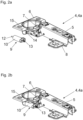
- Figure 2a shows the fitting 4 in the form of a hinge 4a for the movable mounting of the pivoting element 3 relative to the stationary support 2.
- the fitting 4 comprises a first fitting part 5 for attachment to the stationary support 2 and a second fitting part 6 for attachment to the pivoting element 3, the two fitting parts 5, 6 are pivotally connected to one another via at least one articulated lever 7, preferably at least two articulated levers 7.
- the first fitting part 5 has a hinge arm and/or that the second fitting part 6 has a hinge cup.
- the fitting 4 has at least one damper 9, through which a relative movement of the two fitting parts 5, 6 to one another can be damped.
- the at least one damper 9 comprises a damper housing 10 , for example cylindrical, with a piston rod 12 being mounted so as to be displaceable relative to the damper housing 10 .
- the second fitting part 6 has a hole 14, the piston rod 12 of the damper 9 being guided through the hole 14 in an assembled state.
- the damper 9 can be arranged via at least one fastening point 13 on an outer side of the second fitting part 6 .
- the damper 9 In an assembled state, the damper 9 is arranged below a fastening flange 15 of the second fitting part 6 , the second fitting part 6 together with the damper 9 being able to be arranged in regions within a single cylindrical bore of the pivoting element 3 .
- FIG Figure 2b shows the fitting 4 in the form of the hinge 4a according to FIG Figure 2a with the damper 9 in an assembled state.
- FIG 3a shows the damper 9 in a perspective cross section.
- the damper 9 comprises a damper housing 10, at least one fluid chamber 25 arranged in the damper housing 10, a damping fluid arranged in the fluid chamber 25, at least one piston 17 movably mounted in the fluid chamber 25, and at least one, preferably ring-shaped, sealing element 18, which has at least one first Section 18a rests against an inner wall 10a of the fluid chamber 25 or can be applied.
- the damping fluid can contain a hydraulic damping fluid (e.g. silicone oil) and optionally solid particles.
- a hydraulic damping fluid e.g. silicone oil
- optionally solid particles e.g. silicone oil
- the sealing element 18 has at least one, preferably essentially annular, second section 18b, which in normal operation of the damper 9 (ie below a predetermined threshold value of a pressurization of the piston 17) from the inner wall 10a of the fluid chamber 25, preferably forming a column 22 ( Figure 3b ), is spaced.
- the piston 17 has at least one overload channel 23, which is closed by the second section 18b of the sealing element 18 during normal operation of the damper 9 (i.e. below a predetermined threshold value of a pressurization of the piston 17).
- the overload channel 23 can have at least one passage 23a arranged in the piston 17, preferably a plurality of passages 23a.
- the damper 9 also has a restoring spring 19 (for example a compression spring designed as a helical spring), by means of which the piston 17 can be at least partially returned to an initial position after a damping stroke has taken place.
- the return spring 19 can be supported on an end surface 21 of the fluid chamber 25 and pushes the piston 17 in a direction opposite to the damping stroke.
- the damper 9 has at least one volume compensation device 20, by means of which a volume of the damping fluid that can be displaced by the piston rod 12 when it enters the fluid chamber 25 can be compensated.
- the fluid chamber 25 can be closed by a closure element 16 .
- Figure 3b shows the damper 9 according to FIG Figure 3a in a cross section, the sealing element 18 being in a state of rest.
- the sealing element 18 has a first portion 18a, which on the inner wall 10a of Fluid chamber 25 is present or can be applied.
- a second section 18b of the sealing element 18 is spaced apart from the inner wall 10a of the fluid chamber 25 to form a gap 22 .
- the first section 18a and the at least one second section 18b of the sealing element 18 are spaced apart from one another in a longitudinal direction (L) of the damper housing 10 .
- the first section 18a and the at least one second section 18b of the sealing element 18 essentially form a Z-shape in a longitudinal section and at least when the damper 9 is in a resting state.
- the sealing element 18 can be formed from a thermoplastic elastomer (TPE), for example.
- TPE thermoplastic elastomer
- first section 18a and the second section 18b of the sealing element 18 are formed together in one piece and are movably connected to one another, for example via a film hinge.
- the two sections 18a, 18b of the sealing element 18 could be in the form of separate components, in particular also made of different materials.
- the damper 9 has at least one flow channel 27, which is preferably arranged on the inner wall 10a of the fluid chamber 25, the damping fluid flowing through the flow channel 27 when a damping stroke is carried out.
- the at least one spring element 20c is combined in one piece with the at least one seal 20a and/or in one piece with the at least one support element 20b to form a common compensation part 33 .
- 3c 12 shows the damper 9 in an overload situation, in which case a damping stroke takes place with pressure being applied to the piston 17 above a predetermined threshold value.
- the second section 18b can be bent, tilted and/or radially expanded relative to the first section 18a of the sealing element 18 in a direction towards the inner wall 10a of the fluid chamber 25 .
- the gap 22 formed between the sealing element 18 and the inner wall 10a can be reduced and the overload channel 23 of the piston 17 can be opened at least partially.
- a larger quantity of the damping fluid can flow from the high-pressure side to the low-pressure side of the damper 9, so that the increased pressure of the damping fluid is reduced in the event of an overload.
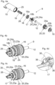
- Figure 4a shows the damper 9 in an exploded view.
- the damper housing 10 has at least one fluid chamber 25 for the displaceable mounting of the piston 17 . After a damping stroke has taken place, the piston 17 can be reset at least partially into an initial position by a force of the return spring 19 .
- a limiting element 26 is to be fastened to the piston 17 , the sealing element 18 being mounted in a mounted state between the limiting element 26 and the piston 17 so that it can be displaced to a limited extent. In this way it is achieved that the sealing element 18 can be spaced at a greater distance from the recesses 24a of the piston 17 during the return by the return spring 19 .
- the piston rod 12 when the piston rod 12 is returned, a larger quantity of damping fluid can flow from the high-pressure side to the low-pressure side, and the piston rod 12 can be returned quickly to an initial position.
- the sealing element 18 can be rotationally symmetrical, with the first section 18a having a larger diameter than the second section 18b.
- Figure 4b shows the damper 9, wherein the damper housing 10 is not shown for the purpose of a better overview.
- the sealing element 18 with the first section 18a and the second section 18b can be displaced to a limited extent in the axial direction between the piston 17 and the limiting element 26 .
- the piston 17 has at least one reset channel 24 with at least one recess 24a, preferably with a plurality of recesses 24a. According to one exemplary embodiment, it can be provided that the at least one recess 24 is arranged on a peripheral edge of the piston 17 .
- FIG. 4c shows the damper 9 according to FIG Figure 4b , wherein the sealing element 18 is not shown for the purpose of a better overview.
- the overload channels 23 of the piston 17 can be clearly seen in this figure, the overload channels 23 comprising at least one passage 23a arranged in the piston 17, preferably a plurality of passages 23a.
- the at least one passage 23a is arranged on a peripheral edge of the piston 17 .
- Figure 4d shows a portion of the piston 17 in a perspective view.
- the piston 17 has at least one axial channel 36, preferably several axial channels 36, for the passage of the damping fluid.
- the axial channels 36 form part of the return channel 24, through which a larger amount of damping fluid can get from a first side of the piston 17 to a second side during the return stroke.
- the at least one axial channel 36 can run parallel, conically or radially to the longitudinal direction (L) of the damper housing 10 .
- the piston 17 has a plurality of axial channels 36 which are arranged on a peripheral edge of the piston 17, preferably symmetrically.
- the piston 17 has a plurality of passages 23a, which can be arranged symmetrically on a peripheral edge of the piston 17.
- the passages 23a can be covered by the second section 18b of the sealing element 18 below a predetermined threshold value of the pressurization of the piston 17 and can be opened above the predetermined threshold value of the pressurization of the piston 17 by the second section 18b of the sealing element 18.
- the piston 17 has at least one disk element 35, on which the at least one sealing element 18 can be supported, at least during one execution of the damping stroke.
- Figure 5a shows the damper 9 in a cross section, the sealing element 18 with the two sections 18a, 18b being visible.
- the first section 18a of the sealing element 18 rests against the inner wall 10a of the fluid chamber 25 or can be placed against the inner wall 10a of the fluid chamber when a damping stroke is being carried out.
- the second section 18b of the sealing element 18 is spaced apart from the inner wall 10a in normal operation, forming a gap 22 .
- the damper 9 has at least one flow channel 27, which is preferably arranged on the inner wall 10a of the fluid chamber 25, the damping fluid flowing through the flow channel 27 when a damping stroke is carried out.
- Two or more flow channels 27 arranged on the inner wall 10a can also be provided.
- the at least one flow channel 27 can be designed as an elongated groove. According to one exemplary embodiment, it can be provided that a cross section of the at least one flow channel 27 changes, preferably continuously decreases, in the direction of the damping stroke.
- Figure 5b shows the in Figure 5a circled area in an enlarged view. If the piston 17 is moved below a predetermined threshold value, the overload channel 23 with the passage 23a is closed by the second section 18b of the sealing element 18. In such normal operation, the damping fluid flows, preferably exclusively, through the at least one flow channel 27.
- An axial gap 34 arranged between the piston 17 and the delimiting element 26a can be seen, through which the sealing element 18 is movably mounted relative to the piston 17.
- the sealing element 18 can be placed against the limiting element 26, with the size of the gap 34 being variable and so when the piston rod 12 is returned, a larger amount of damping fluid can flow from one side of the piston 17 to the other side.
- FIG. 1 shows the overload situation, in which case the piston 17 is moved with a pressurization above a predetermined threshold value.
- the radial gap 22 formed between the piston 17 and the inner wall 10a can be reduced by bending or tilting the second section 18b relative to the first section 18a, the overload channel 23 with the passage 23a being released through the second section 18b of the sealing element 18.
- the damping fluid can therefore flow along the arrow drawn from the high-pressure side to the low-pressure side.
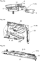
- Figures 6a-6c show different fittings 4 for the movable mounting of a movable furniture part 3a.
- Figure 6a shows a fitting 4 in the form of a hinge 4a, which has a first fitting part 5 for attachment to the stationary support 2 and a second fitting part 6 for attachment to the movable furniture part 3a.
- the first fitting part 5 and the second fitting part 6 are pivotally connected to one another by at least one articulated lever 7, preferably at least two articulated levers 7.
- the damper 9 with the damper housing 10 is placed on the first fitting part 5, with the damper housing 10 being pressed in towards the end of the closing movement of the hinge 4a by the second fitting part 6 relative to the fixed piston rod 12, so that the closing movement of the hinge 4a can be damped.
- Figure 6b shows a fitting 4 in the form of a furniture drive 4b for moving a movable furniture part 3a.
- the furniture drive 4b comprises a base body 28 for attachment to the stationary support 2 (e.g. on the furniture body 2a), an actuating arm arrangement 29 which is arranged on the base body 28 and can be connected to the movable furniture part 3a for moving the Movable furniture part 3a and an energy accumulator 30 for applying force to the actuating arm arrangement 29.
- the damper housing 10 of the damper 9 can be pressed in by a pivotable actuating arm 29a of the actuating arm arrangement 29 relative to the fixed piston rod 12, the closing movement of the actuating arm arrangement 29 being dampable.
- Figure 6c shows a fitting 4 in the form of a drawer pull-out guide 4c for moving a drawer relative to the furniture body 2.
- the drawer pull-out guide 4c comprises at least two guide rails 31, 32 that can be moved relative to one another, with a movement of a guide rail 31, 32 towards the end of the closing movement by the damper 9 with the Damper housing 10 can be damped.
Landscapes
- Fluid-Damping Devices (AREA)
Priority Applications (9)
| Application Number | Priority Date | Filing Date | Title |
|---|---|---|---|
| EP21214294.7A EP4198238B1 (fr) | 2021-12-14 | 2021-12-14 | Amortisseur pour une butée destinée au stockage mobile d'un élément pivotant ou d'un élément d'extraction |
| ES21214294T ES2990054T3 (es) | 2021-12-14 | 2021-12-14 | Amortiguador para un herraje para el montaje móvil de un elemento giratorio o extraíble |
| SI202130171T SI4198238T1 (sl) | 2021-12-14 | 2021-12-14 | Dušilnik za okovje za gibljivo namestitev vihtljivega elementa ali izvlečnega elementa |
| EP22830533.0A EP4448907B1 (fr) | 2021-12-14 | 2022-12-06 | Amortisseur pour une ferrure destinée au support mobile d'un élément pivotant ou d'un élément coulissant |
| JP2024535597A JP7721813B2 (ja) | 2021-12-14 | 2022-12-06 | 旋回エレメントまたは引出しエレメントを運動可能に支承するための金具用のダンパ |
| PCT/EP2022/084580 WO2023110537A1 (fr) | 2021-12-14 | 2022-12-06 | Amortisseur destiné à une ferrure servant au montage mobile d'un élément pivotant ou d'un élément télescopique |
| CN202280082804.3A CN118401735A (zh) | 2021-12-14 | 2022-12-06 | 用于可运动地支承枢转元件或拉出元件的配件的阻尼器 |
| KR1020247017264A KR102935849B1 (ko) | 2021-12-14 | 2022-12-06 | 피봇팅 요소 또는 인출 요소를 이동가능하게 장착하기 위한 피팅에 대한 댐퍼 |
| US18/734,689 US12529256B2 (en) | 2021-12-14 | 2024-06-05 | Damper for a fitting for movably mounting a pivoting element or a pull-out element |
Applications Claiming Priority (1)
| Application Number | Priority Date | Filing Date | Title |
|---|---|---|---|
| EP21214294.7A EP4198238B1 (fr) | 2021-12-14 | 2021-12-14 | Amortisseur pour une butée destinée au stockage mobile d'un élément pivotant ou d'un élément d'extraction |
Publications (2)
| Publication Number | Publication Date |
|---|---|
| EP4198238A1 true EP4198238A1 (fr) | 2023-06-21 |
| EP4198238B1 EP4198238B1 (fr) | 2024-06-12 |
Family
ID=78851295
Family Applications (2)
| Application Number | Title | Priority Date | Filing Date |
|---|---|---|---|
| EP21214294.7A Active EP4198238B1 (fr) | 2021-12-14 | 2021-12-14 | Amortisseur pour une butée destinée au stockage mobile d'un élément pivotant ou d'un élément d'extraction |
| EP22830533.0A Active EP4448907B1 (fr) | 2021-12-14 | 2022-12-06 | Amortisseur pour une ferrure destinée au support mobile d'un élément pivotant ou d'un élément coulissant |
Family Applications After (1)
| Application Number | Title | Priority Date | Filing Date |
|---|---|---|---|
| EP22830533.0A Active EP4448907B1 (fr) | 2021-12-14 | 2022-12-06 | Amortisseur pour une ferrure destinée au support mobile d'un élément pivotant ou d'un élément coulissant |
Country Status (8)
| Country | Link |
|---|---|
| US (1) | US12529256B2 (fr) |
| EP (2) | EP4198238B1 (fr) |
| JP (1) | JP7721813B2 (fr) |
| KR (1) | KR102935849B1 (fr) |
| CN (1) | CN118401735A (fr) |
| ES (1) | ES2990054T3 (fr) |
| SI (1) | SI4198238T1 (fr) |
| WO (1) | WO2023110537A1 (fr) |
Families Citing this family (1)
| Publication number | Priority date | Publication date | Assignee | Title |
|---|---|---|---|---|
| AT525400A1 (de) * | 2021-08-20 | 2023-03-15 | Blum Gmbh Julius | Dämpfer |
Citations (8)
| Publication number | Priority date | Publication date | Assignee | Title |
|---|---|---|---|---|
| US2912069A (en) * | 1955-12-21 | 1959-11-10 | Procedo G M B H | Noiseless piston device |
| KR200382473Y1 (ko) * | 2005-01-19 | 2005-04-20 | 석정희 | 도어의 자동 닫힘장치 |
| EP1563763A1 (fr) * | 2004-02-17 | 2005-08-17 | Miguel Angel Rioja Calvo | Dispositif amortisseur pour meubles |
| WO2007143760A1 (fr) * | 2006-06-13 | 2007-12-21 | Fulterer Gesellschaft M.B.H. | Amortisseur pour meubles |
| AT10342U1 (de) | 2004-09-17 | 2009-01-15 | Blum Gmbh Julius | Fluiddämpfer |
| US8220602B2 (en) * | 2004-06-16 | 2012-07-17 | Alfit Ag | Device for damping or decelerating movable parts or pieces of furniture |
| AT12633U1 (de) * | 2010-08-27 | 2012-09-15 | Blum Gmbh Julius | Dämpfvorrichtung mit überlastsicherung |
| CN105889394A (zh) * | 2015-02-17 | 2016-08-24 | 吴宗信 | 阻尼器 |
Family Cites Families (22)
| Publication number | Priority date | Publication date | Assignee | Title |
|---|---|---|---|---|
| AT12633B (fr) | 1901-09-21 | 1903-07-25 | Andreas Radovanovic | |
| JPS5632152U (fr) * | 1979-08-20 | 1981-03-28 | ||
| JPS5632152A (en) | 1979-08-24 | 1981-04-01 | Canon Inc | Image stabilizing method |
| DE20219411U1 (de) * | 2002-05-27 | 2003-10-16 | Mepla-Werke Lautenschläger GmbH & Co. KG, 64354 Reinheim | Dämpfungsvorrichtung für bewegliche Möbelteile von Möbelstücken |
| WO2003100287A1 (fr) | 2002-05-27 | 2003-12-04 | MEPLA-WERKE LAUTENSCHLäGER GMBH & CO. KG | Dispositif d'amortissement de pieces mobiles de meubles |
| DE10313659B3 (de) * | 2003-03-26 | 2004-09-30 | Zimmer, Günther Stephan | Pneumatische Verzögerungsvorrichtung zum Abbremsen beweglicher Möbelteile |
| TWI225533B (en) * | 2003-05-20 | 2004-12-21 | Jr-Hung Li | A cabinet door bumper |
| KR100814074B1 (ko) | 2007-03-07 | 2008-03-14 | 석정희 | 도어 개폐용 댐핑장치 |
| CN201027890Y (zh) * | 2007-05-01 | 2008-02-27 | 伍志勇 | 家具的阻尼器 |
| DE202009004752U1 (de) * | 2009-04-28 | 2010-09-09 | Druck- und Spritzgußwerk Hettich GmbH & Co. KG | Dämpfer für Möbel |
| ES2735000T3 (es) * | 2012-06-15 | 2019-12-13 | Faringosi Hinges Srl | Amortiguador para bisagras |
| CN203308270U (zh) * | 2013-06-04 | 2013-11-27 | 广东泰明金属制品有限公司 | 家具铰链的阻尼器装置 |
| KR101408768B1 (ko) * | 2014-03-12 | 2014-06-18 | 삼성정밀공업 주식회사 | 압력조절수단을 내장한 가구힌지용 가변형 완충댐퍼 |
| DE102015015170B3 (de) * | 2015-11-26 | 2016-12-15 | Günther Zimmer | Zylinder-Kolben-Einheit mit Ausgleichsdichtelement |
| US10527122B2 (en) * | 2017-02-03 | 2020-01-07 | Beijingwest Industries Co., Ltd. | Hydraulic damper with a hydraulic compression stop arrangement |
| DE102017114475A1 (de) * | 2017-06-29 | 2019-01-03 | Druck- und Spritzgußwerk Hettich GmbH & Co. KG | Dämpfer |
| AT520128B1 (de) | 2017-07-13 | 2025-02-15 | Blum Gmbh Julius | Möbelbeschlag mit wenigstens einem Möbeldämpfer |
| TWI645811B (zh) | 2017-11-06 | 2019-01-01 | 川湖科技股份有限公司 | 可活動傢俱件及其緩衝裝置 |
| DE102017010876B4 (de) * | 2017-11-24 | 2023-06-01 | Günther Zimmer | Zylinder-Kolben-Einheit mit lastabhängiger Drossel |
| GB2576177A (en) * | 2018-08-07 | 2020-02-12 | Titus D O O Dekani | Improvements in dampers |
| CN212249643U (zh) | 2020-03-20 | 2020-12-29 | 广东东泰五金精密制造有限公司 | 一种用于家具的阻尼器结构 |
| EP4460647A4 (fr) * | 2021-12-01 | 2025-12-03 | Samet Kalip Ve Madeni Esya San Ve Tic A S | Amortisseur hydraulique pour portes et tiroirs de meubles |
-
2021
- 2021-12-14 EP EP21214294.7A patent/EP4198238B1/fr active Active
- 2021-12-14 SI SI202130171T patent/SI4198238T1/sl unknown
- 2021-12-14 ES ES21214294T patent/ES2990054T3/es active Active
-
2022
- 2022-12-06 EP EP22830533.0A patent/EP4448907B1/fr active Active
- 2022-12-06 WO PCT/EP2022/084580 patent/WO2023110537A1/fr not_active Ceased
- 2022-12-06 JP JP2024535597A patent/JP7721813B2/ja active Active
- 2022-12-06 KR KR1020247017264A patent/KR102935849B1/ko active Active
- 2022-12-06 CN CN202280082804.3A patent/CN118401735A/zh active Pending
-
2024
- 2024-06-05 US US18/734,689 patent/US12529256B2/en active Active
Patent Citations (8)
| Publication number | Priority date | Publication date | Assignee | Title |
|---|---|---|---|---|
| US2912069A (en) * | 1955-12-21 | 1959-11-10 | Procedo G M B H | Noiseless piston device |
| EP1563763A1 (fr) * | 2004-02-17 | 2005-08-17 | Miguel Angel Rioja Calvo | Dispositif amortisseur pour meubles |
| US8220602B2 (en) * | 2004-06-16 | 2012-07-17 | Alfit Ag | Device for damping or decelerating movable parts or pieces of furniture |
| AT10342U1 (de) | 2004-09-17 | 2009-01-15 | Blum Gmbh Julius | Fluiddämpfer |
| KR200382473Y1 (ko) * | 2005-01-19 | 2005-04-20 | 석정희 | 도어의 자동 닫힘장치 |
| WO2007143760A1 (fr) * | 2006-06-13 | 2007-12-21 | Fulterer Gesellschaft M.B.H. | Amortisseur pour meubles |
| AT12633U1 (de) * | 2010-08-27 | 2012-09-15 | Blum Gmbh Julius | Dämpfvorrichtung mit überlastsicherung |
| CN105889394A (zh) * | 2015-02-17 | 2016-08-24 | 吴宗信 | 阻尼器 |
Also Published As
| Publication number | Publication date |
|---|---|
| EP4448907B1 (fr) | 2026-04-08 |
| US12529256B2 (en) | 2026-01-20 |
| JP2024543693A (ja) | 2024-11-21 |
| EP4198238B1 (fr) | 2024-06-12 |
| KR102935849B1 (ko) | 2026-03-09 |
| SI4198238T1 (sl) | 2024-09-30 |
| KR20240090897A (ko) | 2024-06-21 |
| CN118401735A (zh) | 2024-07-26 |
| JP7721813B2 (ja) | 2025-08-12 |
| WO2023110537A1 (fr) | 2023-06-22 |
| US20240318490A1 (en) | 2024-09-26 |
| EP4448907A1 (fr) | 2024-10-23 |
| ES2990054T3 (es) | 2024-11-28 |
Similar Documents
| Publication | Publication Date | Title |
|---|---|---|
| WO2006029421A1 (fr) | Amortisseur fluidique | |
| EP2796650A1 (fr) | Charnière de meuble | |
| EP1884614B1 (fr) | Agencement de charnière | |
| EP2010741A2 (fr) | Amortisseur pour meubles | |
| EP1756446B1 (fr) | Systeme d'amortissement ou de freinage de pieces mobiles de meubles | |
| EP1907657A1 (fr) | Element d'amortissement | |
| EP4178395B1 (fr) | Amortisseur de meuble | |
| EP1255013B1 (fr) | Ferrure pour meubles avec dispositif amortisseur et freinage | |
| EP4198238B1 (fr) | Amortisseur pour une butée destinée au stockage mobile d'un élément pivotant ou d'un élément d'extraction | |
| DE3937306C2 (fr) | ||
| AT508069B1 (de) | Möbelscharnier | |
| AT520128B1 (de) | Möbelbeschlag mit wenigstens einem Möbeldämpfer | |
| DE19734466C1 (de) | Blockierbares Kolben-Zylinderaggregat | |
| WO2017152195A1 (fr) | Amortisseur pour meuble | |
| DE20302120U1 (de) | Flüssigkeitsdämpfer | |
| DE19820404A1 (de) | Blockierbares Kolben-Zylinderaggregat | |
| EP3683395A1 (fr) | Dispositif d'amortissement des mouvements d'une pièce de mobilier et dispositif de guidage | |
| EP1703058B1 (fr) | Ferrure pour un meuble d'angle, en particulier un meuble d'angle de cuisine | |
| AT17731U1 (de) | Möbeldämpfer | |
| DE60006389T2 (de) | Gasfeder | |
| WO2023019281A2 (fr) | Amortisseur | |
| AT18223U1 (de) | Möbelscharnier | |
| DE2714529A1 (de) | Daempfungsvorrichtung fuer schiebefenster | |
| AT17733U1 (de) | Möbeldämpfer | |
| DE202005020351U1 (de) | Hydraulikpuffer |
Legal Events
| Date | Code | Title | Description |
|---|---|---|---|
| PUAI | Public reference made under article 153(3) epc to a published international application that has entered the european phase |
Free format text: ORIGINAL CODE: 0009012 |
|
| STAA | Information on the status of an ep patent application or granted ep patent |
Free format text: STATUS: THE APPLICATION HAS BEEN PUBLISHED |
|
| AK | Designated contracting states |
Kind code of ref document: A1 Designated state(s): AL AT BE BG CH CY CZ DE DK EE ES FI FR GB GR HR HU IE IS IT LI LT LU LV MC MK MT NL NO PL PT RO RS SE SI SK SM TR |
|
| STAA | Information on the status of an ep patent application or granted ep patent |
Free format text: STATUS: REQUEST FOR EXAMINATION WAS MADE |
|
| 17P | Request for examination filed |
Effective date: 20230705 |
|
| RBV | Designated contracting states (corrected) |
Designated state(s): AL AT BE BG CH CY CZ DE DK EE ES FI FR GB GR HR HU IE IS IT LI LT LU LV MC MK MT NL NO PL PT RO RS SE SI SK SM TR |
|
| P01 | Opt-out of the competence of the unified patent court (upc) registered |
Effective date: 20230803 |
|
| STAA | Information on the status of an ep patent application or granted ep patent |
Free format text: STATUS: EXAMINATION IS IN PROGRESS |
|
| 17Q | First examination report despatched |
Effective date: 20231211 |
|
| GRAP | Despatch of communication of intention to grant a patent |
Free format text: ORIGINAL CODE: EPIDOSNIGR1 |
|
| STAA | Information on the status of an ep patent application or granted ep patent |
Free format text: STATUS: GRANT OF PATENT IS INTENDED |
|
| INTG | Intention to grant announced |
Effective date: 20240404 |
|
| GRAS | Grant fee paid |
Free format text: ORIGINAL CODE: EPIDOSNIGR3 |
|
| GRAA | (expected) grant |
Free format text: ORIGINAL CODE: 0009210 |
|
| STAA | Information on the status of an ep patent application or granted ep patent |
Free format text: STATUS: THE PATENT HAS BEEN GRANTED |
|
| AK | Designated contracting states |
Kind code of ref document: B1 Designated state(s): AL AT BE BG CH CY CZ DE DK EE ES FI FR GB GR HR HU IE IS IT LI LT LU LV MC MK MT NL NO PL PT RO RS SE SI SK SM TR |
|
| REG | Reference to a national code |
Ref country code: GB Ref legal event code: FG4D Free format text: NOT ENGLISH |
|
| REG | Reference to a national code |
Ref country code: CH Ref legal event code: EP |
|
| REG | Reference to a national code |
Ref country code: DE Ref legal event code: R096 Ref document number: 502021003987 Country of ref document: DE |
|
| REG | Reference to a national code |
Ref country code: IE Ref legal event code: FG4D Free format text: LANGUAGE OF EP DOCUMENT: GERMAN |
|
| PG25 | Lapsed in a contracting state [announced via postgrant information from national office to epo] |
Ref country code: BG Free format text: LAPSE BECAUSE OF FAILURE TO SUBMIT A TRANSLATION OF THE DESCRIPTION OR TO PAY THE FEE WITHIN THE PRESCRIBED TIME-LIMIT Effective date: 20240612 |
|
| PG25 | Lapsed in a contracting state [announced via postgrant information from national office to epo] |
Ref country code: FI Free format text: LAPSE BECAUSE OF FAILURE TO SUBMIT A TRANSLATION OF THE DESCRIPTION OR TO PAY THE FEE WITHIN THE PRESCRIBED TIME-LIMIT Effective date: 20240612 Ref country code: HR Free format text: LAPSE BECAUSE OF FAILURE TO SUBMIT A TRANSLATION OF THE DESCRIPTION OR TO PAY THE FEE WITHIN THE PRESCRIBED TIME-LIMIT Effective date: 20240612 |
|
| REG | Reference to a national code |
Ref country code: LT Ref legal event code: MG9D |
|
| PG25 | Lapsed in a contracting state [announced via postgrant information from national office to epo] |
Ref country code: GR Free format text: LAPSE BECAUSE OF FAILURE TO SUBMIT A TRANSLATION OF THE DESCRIPTION OR TO PAY THE FEE WITHIN THE PRESCRIBED TIME-LIMIT Effective date: 20240913 |
|
| REG | Reference to a national code |
Ref country code: NL Ref legal event code: MP Effective date: 20240612 |
|
| PG25 | Lapsed in a contracting state [announced via postgrant information from national office to epo] |
Ref country code: LV Free format text: LAPSE BECAUSE OF FAILURE TO SUBMIT A TRANSLATION OF THE DESCRIPTION OR TO PAY THE FEE WITHIN THE PRESCRIBED TIME-LIMIT Effective date: 20240612 |
|
| PG25 | Lapsed in a contracting state [announced via postgrant information from national office to epo] |
Ref country code: NO Free format text: LAPSE BECAUSE OF FAILURE TO SUBMIT A TRANSLATION OF THE DESCRIPTION OR TO PAY THE FEE WITHIN THE PRESCRIBED TIME-LIMIT Effective date: 20240912 Ref country code: LV Free format text: LAPSE BECAUSE OF FAILURE TO SUBMIT A TRANSLATION OF THE DESCRIPTION OR TO PAY THE FEE WITHIN THE PRESCRIBED TIME-LIMIT Effective date: 20240612 Ref country code: HR Free format text: LAPSE BECAUSE OF FAILURE TO SUBMIT A TRANSLATION OF THE DESCRIPTION OR TO PAY THE FEE WITHIN THE PRESCRIBED TIME-LIMIT Effective date: 20240612 Ref country code: GR Free format text: LAPSE BECAUSE OF FAILURE TO SUBMIT A TRANSLATION OF THE DESCRIPTION OR TO PAY THE FEE WITHIN THE PRESCRIBED TIME-LIMIT Effective date: 20240913 Ref country code: FI Free format text: LAPSE BECAUSE OF FAILURE TO SUBMIT A TRANSLATION OF THE DESCRIPTION OR TO PAY THE FEE WITHIN THE PRESCRIBED TIME-LIMIT Effective date: 20240612 Ref country code: BG Free format text: LAPSE BECAUSE OF FAILURE TO SUBMIT A TRANSLATION OF THE DESCRIPTION OR TO PAY THE FEE WITHIN THE PRESCRIBED TIME-LIMIT Effective date: 20240612 Ref country code: RS Free format text: LAPSE BECAUSE OF FAILURE TO SUBMIT A TRANSLATION OF THE DESCRIPTION OR TO PAY THE FEE WITHIN THE PRESCRIBED TIME-LIMIT Effective date: 20240912 |
|
| PG25 | Lapsed in a contracting state [announced via postgrant information from national office to epo] |
Ref country code: NL Free format text: LAPSE BECAUSE OF FAILURE TO SUBMIT A TRANSLATION OF THE DESCRIPTION OR TO PAY THE FEE WITHIN THE PRESCRIBED TIME-LIMIT Effective date: 20240612 |
|
| REG | Reference to a national code |
Ref country code: ES Ref legal event code: FG2A Ref document number: 2990054 Country of ref document: ES Kind code of ref document: T3 Effective date: 20241128 |
|
| PG25 | Lapsed in a contracting state [announced via postgrant information from national office to epo] |
Ref country code: NL Free format text: LAPSE BECAUSE OF FAILURE TO SUBMIT A TRANSLATION OF THE DESCRIPTION OR TO PAY THE FEE WITHIN THE PRESCRIBED TIME-LIMIT Effective date: 20240612 |
|
| PG25 | Lapsed in a contracting state [announced via postgrant information from national office to epo] |
Ref country code: PT Free format text: LAPSE BECAUSE OF FAILURE TO SUBMIT A TRANSLATION OF THE DESCRIPTION OR TO PAY THE FEE WITHIN THE PRESCRIBED TIME-LIMIT Effective date: 20241014 |
|
| PG25 | Lapsed in a contracting state [announced via postgrant information from national office to epo] |
Ref country code: PT Free format text: LAPSE BECAUSE OF FAILURE TO SUBMIT A TRANSLATION OF THE DESCRIPTION OR TO PAY THE FEE WITHIN THE PRESCRIBED TIME-LIMIT Effective date: 20241014 |
|
| PG25 | Lapsed in a contracting state [announced via postgrant information from national office to epo] |
Ref country code: PL Free format text: LAPSE BECAUSE OF FAILURE TO SUBMIT A TRANSLATION OF THE DESCRIPTION OR TO PAY THE FEE WITHIN THE PRESCRIBED TIME-LIMIT Effective date: 20240612 |
|
| PG25 | Lapsed in a contracting state [announced via postgrant information from national office to epo] |
Ref country code: EE Free format text: LAPSE BECAUSE OF FAILURE TO SUBMIT A TRANSLATION OF THE DESCRIPTION OR TO PAY THE FEE WITHIN THE PRESCRIBED TIME-LIMIT Effective date: 20240612 |
|
| PG25 | Lapsed in a contracting state [announced via postgrant information from national office to epo] |
Ref country code: IS Free format text: LAPSE BECAUSE OF FAILURE TO SUBMIT A TRANSLATION OF THE DESCRIPTION OR TO PAY THE FEE WITHIN THE PRESCRIBED TIME-LIMIT Effective date: 20241012 |
|
| PG25 | Lapsed in a contracting state [announced via postgrant information from national office to epo] |
Ref country code: CZ Free format text: LAPSE BECAUSE OF FAILURE TO SUBMIT A TRANSLATION OF THE DESCRIPTION OR TO PAY THE FEE WITHIN THE PRESCRIBED TIME-LIMIT Effective date: 20240612 |
|
| PG25 | Lapsed in a contracting state [announced via postgrant information from national office to epo] |
Ref country code: SK Free format text: LAPSE BECAUSE OF FAILURE TO SUBMIT A TRANSLATION OF THE DESCRIPTION OR TO PAY THE FEE WITHIN THE PRESCRIBED TIME-LIMIT Effective date: 20240612 Ref country code: RO Free format text: LAPSE BECAUSE OF FAILURE TO SUBMIT A TRANSLATION OF THE DESCRIPTION OR TO PAY THE FEE WITHIN THE PRESCRIBED TIME-LIMIT Effective date: 20240612 |
|
| PG25 | Lapsed in a contracting state [announced via postgrant information from national office to epo] |
Ref country code: SM Free format text: LAPSE BECAUSE OF FAILURE TO SUBMIT A TRANSLATION OF THE DESCRIPTION OR TO PAY THE FEE WITHIN THE PRESCRIBED TIME-LIMIT Effective date: 20240612 |
|
| PG25 | Lapsed in a contracting state [announced via postgrant information from national office to epo] |
Ref country code: SM Free format text: LAPSE BECAUSE OF FAILURE TO SUBMIT A TRANSLATION OF THE DESCRIPTION OR TO PAY THE FEE WITHIN THE PRESCRIBED TIME-LIMIT Effective date: 20240612 Ref country code: SK Free format text: LAPSE BECAUSE OF FAILURE TO SUBMIT A TRANSLATION OF THE DESCRIPTION OR TO PAY THE FEE WITHIN THE PRESCRIBED TIME-LIMIT Effective date: 20240612 Ref country code: RO Free format text: LAPSE BECAUSE OF FAILURE TO SUBMIT A TRANSLATION OF THE DESCRIPTION OR TO PAY THE FEE WITHIN THE PRESCRIBED TIME-LIMIT Effective date: 20240612 Ref country code: PL Free format text: LAPSE BECAUSE OF FAILURE TO SUBMIT A TRANSLATION OF THE DESCRIPTION OR TO PAY THE FEE WITHIN THE PRESCRIBED TIME-LIMIT Effective date: 20240612 Ref country code: IS Free format text: LAPSE BECAUSE OF FAILURE TO SUBMIT A TRANSLATION OF THE DESCRIPTION OR TO PAY THE FEE WITHIN THE PRESCRIBED TIME-LIMIT Effective date: 20241012 Ref country code: EE Free format text: LAPSE BECAUSE OF FAILURE TO SUBMIT A TRANSLATION OF THE DESCRIPTION OR TO PAY THE FEE WITHIN THE PRESCRIBED TIME-LIMIT Effective date: 20240612 Ref country code: CZ Free format text: LAPSE BECAUSE OF FAILURE TO SUBMIT A TRANSLATION OF THE DESCRIPTION OR TO PAY THE FEE WITHIN THE PRESCRIBED TIME-LIMIT Effective date: 20240612 |
|
| REG | Reference to a national code |
Ref country code: DE Ref legal event code: R097 Ref document number: 502021003987 Country of ref document: DE |
|
| PG25 | Lapsed in a contracting state [announced via postgrant information from national office to epo] |
Ref country code: DK Free format text: LAPSE BECAUSE OF FAILURE TO SUBMIT A TRANSLATION OF THE DESCRIPTION OR TO PAY THE FEE WITHIN THE PRESCRIBED TIME-LIMIT Effective date: 20240612 |
|
| PLBE | No opposition filed within time limit |
Free format text: ORIGINAL CODE: 0009261 |
|
| STAA | Information on the status of an ep patent application or granted ep patent |
Free format text: STATUS: NO OPPOSITION FILED WITHIN TIME LIMIT |
|
| 26N | No opposition filed |
Effective date: 20250313 |
|
| PG25 | Lapsed in a contracting state [announced via postgrant information from national office to epo] |
Ref country code: MC Free format text: LAPSE BECAUSE OF FAILURE TO SUBMIT A TRANSLATION OF THE DESCRIPTION OR TO PAY THE FEE WITHIN THE PRESCRIBED TIME-LIMIT Effective date: 20240612 |
|
| REG | Reference to a national code |
Ref country code: CH Ref legal event code: PL |
|
| PG25 | Lapsed in a contracting state [announced via postgrant information from national office to epo] |
Ref country code: LU Free format text: LAPSE BECAUSE OF NON-PAYMENT OF DUE FEES Effective date: 20241214 |
|
| PG25 | Lapsed in a contracting state [announced via postgrant information from national office to epo] |
Ref country code: SE Free format text: LAPSE BECAUSE OF FAILURE TO SUBMIT A TRANSLATION OF THE DESCRIPTION OR TO PAY THE FEE WITHIN THE PRESCRIBED TIME-LIMIT Effective date: 20240612 |
|
| REG | Reference to a national code |
Ref country code: BE Ref legal event code: MM Effective date: 20241231 |
|
| PG25 | Lapsed in a contracting state [announced via postgrant information from national office to epo] |
Ref country code: BE Free format text: LAPSE BECAUSE OF NON-PAYMENT OF DUE FEES Effective date: 20241231 |
|
| PG25 | Lapsed in a contracting state [announced via postgrant information from national office to epo] |
Ref country code: FR Free format text: LAPSE BECAUSE OF NON-PAYMENT OF DUE FEES Effective date: 20241231 |
|
| PG25 | Lapsed in a contracting state [announced via postgrant information from national office to epo] |
Ref country code: CH Free format text: LAPSE BECAUSE OF NON-PAYMENT OF DUE FEES Effective date: 20241231 |
|
| PG25 | Lapsed in a contracting state [announced via postgrant information from national office to epo] |
Ref country code: IE Free format text: LAPSE BECAUSE OF NON-PAYMENT OF DUE FEES Effective date: 20241214 |
|
| PGFP | Annual fee paid to national office [announced via postgrant information from national office to epo] |
Ref country code: AT Payment date: 20260113 Year of fee payment: 5 |
|
| PGFP | Annual fee paid to national office [announced via postgrant information from national office to epo] |
Ref country code: IT Payment date: 20251218 Year of fee payment: 5 |
|
| PGFP | Annual fee paid to national office [announced via postgrant information from national office to epo] |
Ref country code: TR Payment date: 20251126 Year of fee payment: 5 |
|
| PGFP | Annual fee paid to national office [announced via postgrant information from national office to epo] |
Ref country code: SI Payment date: 20251124 Year of fee payment: 5 |
|
| PGFP | Annual fee paid to national office [announced via postgrant information from national office to epo] |
Ref country code: ES Payment date: 20260122 Year of fee payment: 5 |
|
| PGFP | Annual fee paid to national office [announced via postgrant information from national office to epo] |
Ref country code: DE Payment date: 20251229 Year of fee payment: 5 |