EP4198342A1 - Mehrganggetriebe für ein fahrzeug, fahrzeug und verfahren zum betrieb eines mehrganggetriebes - Google Patents
Mehrganggetriebe für ein fahrzeug, fahrzeug und verfahren zum betrieb eines mehrganggetriebes Download PDFInfo
- Publication number
- EP4198342A1 EP4198342A1 EP21214870.4A EP21214870A EP4198342A1 EP 4198342 A1 EP4198342 A1 EP 4198342A1 EP 21214870 A EP21214870 A EP 21214870A EP 4198342 A1 EP4198342 A1 EP 4198342A1
- Authority
- EP
- European Patent Office
- Prior art keywords
- gear
- gear wheel
- clutch
- shaft
- output shaft
- Prior art date
- Legal status (The legal status is an assumption and is not a legal conclusion. Google has not performed a legal analysis and makes no representation as to the accuracy of the status listed.)
- Granted
Links
Images


Classifications
-
- F—MECHANICAL ENGINEERING; LIGHTING; HEATING; WEAPONS; BLASTING
- F16—ENGINEERING ELEMENTS AND UNITS; GENERAL MEASURES FOR PRODUCING AND MAINTAINING EFFECTIVE FUNCTIONING OF MACHINES OR INSTALLATIONS; THERMAL INSULATION IN GENERAL
- F16H—GEARING
- F16H3/00—Toothed gearings for conveying rotary motion with variable gear ratio or for reversing rotary motion
- F16H3/44—Toothed gearings for conveying rotary motion with variable gear ratio or for reversing rotary motion using gears having orbital motion
- F16H3/62—Gearings having three or more central gears
- F16H3/66—Gearings having three or more central gears composed of a number of gear trains without drive passing from one train to another
- F16H3/666—Gearings having three or more central gears composed of a number of gear trains without drive passing from one train to another with intermeshing orbital gears
-
- F—MECHANICAL ENGINEERING; LIGHTING; HEATING; WEAPONS; BLASTING
- F16—ENGINEERING ELEMENTS AND UNITS; GENERAL MEASURES FOR PRODUCING AND MAINTAINING EFFECTIVE FUNCTIONING OF MACHINES OR INSTALLATIONS; THERMAL INSULATION IN GENERAL
- F16H—GEARING
- F16H3/00—Toothed gearings for conveying rotary motion with variable gear ratio or for reversing rotary motion
- F16H3/02—Toothed gearings for conveying rotary motion with variable gear ratio or for reversing rotary motion without gears having orbital motion
- F16H3/04—Toothed gearings for conveying rotary motion with variable gear ratio or for reversing rotary motion without gears having orbital motion with internally-toothed gears
-
- F—MECHANICAL ENGINEERING; LIGHTING; HEATING; WEAPONS; BLASTING
- F16—ENGINEERING ELEMENTS AND UNITS; GENERAL MEASURES FOR PRODUCING AND MAINTAINING EFFECTIVE FUNCTIONING OF MACHINES OR INSTALLATIONS; THERMAL INSULATION IN GENERAL
- F16H—GEARING
- F16H3/00—Toothed gearings for conveying rotary motion with variable gear ratio or for reversing rotary motion
- F16H3/02—Toothed gearings for conveying rotary motion with variable gear ratio or for reversing rotary motion without gears having orbital motion
- F16H3/08—Toothed gearings for conveying rotary motion with variable gear ratio or for reversing rotary motion without gears having orbital motion exclusively or essentially with continuously meshing gears, that can be disengaged from their shafts
- F16H3/085—Toothed gearings for conveying rotary motion with variable gear ratio or for reversing rotary motion without gears having orbital motion exclusively or essentially with continuously meshing gears, that can be disengaged from their shafts with more than one output shaft
-
- F—MECHANICAL ENGINEERING; LIGHTING; HEATING; WEAPONS; BLASTING
- F16—ENGINEERING ELEMENTS AND UNITS; GENERAL MEASURES FOR PRODUCING AND MAINTAINING EFFECTIVE FUNCTIONING OF MACHINES OR INSTALLATIONS; THERMAL INSULATION IN GENERAL
- F16H—GEARING
- F16H2200/00—Transmissions for multiple ratios
- F16H2200/003—Transmissions for multiple ratios characterised by the number of forward speeds
- F16H2200/0052—Transmissions for multiple ratios characterised by the number of forward speeds the gear ratios comprising six forward speeds
-
- F—MECHANICAL ENGINEERING; LIGHTING; HEATING; WEAPONS; BLASTING
- F16—ENGINEERING ELEMENTS AND UNITS; GENERAL MEASURES FOR PRODUCING AND MAINTAINING EFFECTIVE FUNCTIONING OF MACHINES OR INSTALLATIONS; THERMAL INSULATION IN GENERAL
- F16H—GEARING
- F16H2200/00—Transmissions for multiple ratios
- F16H2200/003—Transmissions for multiple ratios characterised by the number of forward speeds
- F16H2200/0065—Transmissions for multiple ratios characterised by the number of forward speeds the gear ratios comprising nine forward speeds
-
- F—MECHANICAL ENGINEERING; LIGHTING; HEATING; WEAPONS; BLASTING
- F16—ENGINEERING ELEMENTS AND UNITS; GENERAL MEASURES FOR PRODUCING AND MAINTAINING EFFECTIVE FUNCTIONING OF MACHINES OR INSTALLATIONS; THERMAL INSULATION IN GENERAL
- F16H—GEARING
- F16H2200/00—Transmissions for multiple ratios
- F16H2200/003—Transmissions for multiple ratios characterised by the number of forward speeds
- F16H2200/0073—Transmissions for multiple ratios characterised by the number of forward speeds the gear ratios comprising eleven forward speeds
-
- F—MECHANICAL ENGINEERING; LIGHTING; HEATING; WEAPONS; BLASTING
- F16—ENGINEERING ELEMENTS AND UNITS; GENERAL MEASURES FOR PRODUCING AND MAINTAINING EFFECTIVE FUNCTIONING OF MACHINES OR INSTALLATIONS; THERMAL INSULATION IN GENERAL
- F16H—GEARING
- F16H2200/00—Transmissions for multiple ratios
- F16H2200/20—Transmissions using gears with orbital motion
- F16H2200/2002—Transmissions using gears with orbital motion characterised by the number of sets of orbital gears
- F16H2200/2007—Transmissions using gears with orbital motion characterised by the number of sets of orbital gears with two sets of orbital gears
-
- F—MECHANICAL ENGINEERING; LIGHTING; HEATING; WEAPONS; BLASTING
- F16—ENGINEERING ELEMENTS AND UNITS; GENERAL MEASURES FOR PRODUCING AND MAINTAINING EFFECTIVE FUNCTIONING OF MACHINES OR INSTALLATIONS; THERMAL INSULATION IN GENERAL
- F16H—GEARING
- F16H3/00—Toothed gearings for conveying rotary motion with variable gear ratio or for reversing rotary motion
- F16H3/006—Toothed gearings for conveying rotary motion with variable gear ratio or for reversing rotary motion power being selectively transmitted by parallel flow paths, e.g. dual clutch transmissions
Definitions
- the present disclosure relates to a multi-speed transmission for a vehicle.
- the transmission has an extension in an axial direction and comprises a first input shaft, a second input shaft, a first output shaft, a second output shaft, a first intermediate shaft and a second intermediate shaft.
- the disclosure further relates to a vehicle comprising a multi-speed transmission, and a method for operating a multi-speed transmission.
- Multi-speed transmissions are used in vehicle applications for providing different gear ratios between at least one power unit and one or more driving wheels of a vehicle.
- the transmission is part of a vehicle powertrain system and is configured for providing the different gear ratios depending on differing driving conditions of the vehicle.
- the at least one power unit may for example be arranged as one or more electric motors, one or more internal combustion engines, or combinations of electric motors and internal combustion engines.
- the transmission may be arranged within the vehicle in a suitable position for efficient power transfer between the at least one power unit and the one or more driving wheels.
- One common issue with transmission systems that can deliver different speed ratios is that they require relatively large space in the vehicle. This is not desired from a packing and weight perspective, and further due to the complex designs of multi-speed transmissions they involve a high number of components leading to reduced efficiency and high costs.
- An object of the present disclosure is to provide a multi-speed transmission for a vehicle, a vehicle comprising a multi-speed transmission, and a method for operating a multi-speed transmission, where the previously mentioned problems are avoided.
- This object is at least partly achieved by the features of the independent claims.
- the dependent claims contain further developments of the multi-speed transmission for a vehicle, and the method for operating a multi-speed transmission.
- the disclosure concerns a multi-speed transmission for a vehicle, where the transmission has an extension in an axial direction and comprises a first input shaft, a second input shaft, a first output shaft, a second output shaft, a first intermediate shaft and a second intermediate shaft.
- the transmission further comprises an annulus internally toothed first ring gear drivingly connected to the second input shaft and an annulus internally toothed second ring gear releasably connected to the first ring gear.
- the first intermediate shaft comprises a first gear wheel in engagement with the first ring gear and a second gear wheel in engagement with the second ring gear.
- the second intermediate shaft comprises a third gear wheel in engagement with the first ring gear and a fourth gear wheel in engagement with the second ring gear.
- the first output shaft comprises a fifth gear wheel in engagement with second gear wheel
- the second output shaft comprises a sixth gear wheel in engagement with the fourth gear wheel.
- the first ring gear, the first gear wheel, and the third gear wheel are arranged in a first axial plane.
- the second ring gear, the second gear wheel, and the fifth gear wheel are arranged in a second axial plane.
- the second ring gear, the fourth gear wheel, and the sixth gear wheel are arranged in a third axial plane.
- the first intermediate shaft and the second intermediate shaft with the respective gear wheels are arranged inside the first ring gear and the second ring gear for enabling the compact layout of the transmission.
- the few components involved is providing a compact multi-speed transmission that is simple in design, and the multi-speed transmission with these features are enabling reduced required space, weight, cost, and improved system efficiency.
- a plurality of different gear ratios between torque input into the transmission and torque output from the transmission can be easily achieved.
- the first ring gear and the second ring gear are concentrically arranged in relation to each other and separated in the axial direction.
- the first ring gear and the second ring gear are releasably connected to each other via a first clutch.
- the first intermediate shaft comprises a second clutch arranged between the first gear wheel and the second gear wheel, and the first gear wheel and the second gear wheel are releasably connected to each other via the second clutch.
- the second intermediate shaft comprises a third clutch arranged between the third gear wheel and the fourth gear wheel, and the third gear wheel and the fourth gear wheel are releasably connected to each other via the third clutch.
- the first clutch is used for selectively connecting the first ring gear and the second ring gear to each other, and for disconnecting first ring gear and the second ring gear from each other. By selectively connecting or disconnecting the first clutch, torque transfer with different gear ratios is enabled.
- the second clutch and the third clutch can each be arranged in connected and disconnected states, and by selectively connecting or disconnecting the clutches torque transfer with different gear ratios is efficiently enabled.
- the first input shaft and the first output shaft are connected to each other and formed as a common shaft structure extending in the axial direction.
- torque can be transferred directly from the first input shaft to the first output shaft for providing a gear ratio.
- the first axial plane, the second axial plane, and the third axial plane are arranged in a parallel relationship to each other and separated in the axial direction of the transmission.
- the ring gears and the gear wheels are separated in the axial direction into the different parallel planes for enabling the simple and efficient construction of the transmission.
- the first input shaft, the second input shaft, the first output shaft, the second output shaft, the first intermediate shaft and the second intermediate shaft are arranged in a parallel relationship to each other in the axial direction of the transmission.
- the parallel relationship of the shafts is providing a simple construction with efficient engagement between the components involved, enabling the compact design of the transmission.
- the first input shaft and the second input shaft are concentrically arranged in relation to each other.
- the first input shaft is arranged as an inner shaft and the second input shaft as an outer shaft concentrically outside the first input shaft.
- the first output shaft and the second output shaft are concentrically arranged in relation to each other.
- the first output shaft is arranged as an inner shaft and the second output shaft as an outer shaft concentrically outside the first output shaft.
- the first input shaft may be arranged as an inner shaft and the second input shaft as an outer hollow shaft concentrically outside the first input shaft.
- the first input shaft and the second input shaft are arranged to rotate independently of each other and a dual clutch or similar arrangement connected to the input shafts may be used for transferring torque from at least one power unit to one of the first input shaft and the second input shaft.
- the first output shaft may be arranged as an inner shaft and the second output shaft as an outer hollow shaft concentrically outside the first output shaft.
- Each of the first output shaft and the second output shaft is arranged for transferring torque to one or more driving wheels of the vehicle.
- the first gear wheel and the third gear wheel are arranged on radially opposite sides of the first input gear shaft and the first output gear shaft.
- the second gear wheel and the fourth gear wheel are arranged on radially opposite sides of the first input gear shaft and the first output gear shaft.
- the second output shaft further comprises a seventh gear wheel in engagement with the fourth gear wheel via an idler gear.
- the second output shaft comprises a fourth clutch arranged for selectively connecting one of the sixth gear wheel and the seventh gear wheel to the second output shaft and disconnecting the other of the sixth gear wheel and the seventh gear wheel from the second output shaft.
- the disclosure further concerns a vehicle comprising a multi-speed transmission, as described above.
- the disclosure further concerns a method for operating a multi-speed transmission for a vehicle.
- the transmission has an extension in an axial direction and comprises a first input shaft, a second input shaft, a first output shaft, a second output shaft, a first intermediate shaft and a second intermediate shaft.
- the transmission further comprises an annulus internally toothed first ring gear drivingly connected to the second input shaft and an annulus internally toothed second ring gear releasably connected to the first ring gear.
- the first intermediate shaft comprises a first gear wheel in engagement with the first ring gear and a second gear wheel in engagement with the second ring gear.
- the second intermediate shaft comprises a third gear wheel in engagement with the first ring gear and a fourth gear wheel in engagement with the second ring gear.
- the first output shaft comprises a fifth gear wheel in engagement with the second gear wheel
- the second output shaft comprises a sixth gear wheel in engagement with the fourth gear wheel.
- the first ring gear, the first gear wheel, and the third gear wheel are arranged in a first axial plane.
- the second ring gear, the second gear wheel, and the fifth gear wheel are arranged in a second axial plane.
- the second ring gear, the fourth gear wheel, and the sixth gear wheel are arranged in a third axial plane.
- the first ring gear and the second ring gear are releasably connected to each other via a first clutch
- the first gear wheel and the second gear wheel are releasably connected to each other via a second clutch arranged on the first intermediate shaft
- the third gear wheel and the fourth gear wheel are releasably connected to each other via a third clutch arranged on the second intermediate shaft.
- the method comprises the steps: operating the first clutch, the second clutch, and the third clutch between connected and disconnected modes for providing different gear ratios of the multi-speed transmission.
- the multi-speed transmission is constructed with very few components, and a compact and efficient multi-speed transmission providing the different gear ratios is therefore achieved.
- the first intermediate shaft and the second intermediate shaft with the respective gearwheels are arranged inside the first ring gear and the second ring gear for enabling the compact layout of the transmission.
- the few components involved is providing a low volume construction that is simple in design, and the multi-speed transmission with these features are enabling reduced required space, weight, cost, and improved system efficiency.
- the clutches can be arranged in connected and disconnected states, and by selectively connecting or disconnecting the clutches torque transfer with different gear ratios is efficiently enabled.
- a control unit is used for selecting the connection or disconnection of the clutches, for delivering a correct gear ratio depending on driving conditions of the vehicle.
- the method further comprises the steps: receiving a command for operating the transmission with a first gear ratio; transferring torque from the first input shaft directly to the first output shaft for providing the first gear ratio.
- the command is received from the control unit and is suitably based on the driving conditions of the vehicle.
- the method further comprises the steps: receiving a command for operating the transmission with a second gear ratio or a seventh gear ratio; connecting the first clutch, disconnecting the second clutch, and disconnecting the third clutch; transferring torque from the second input shaft to the first output shaft via the first ring gear, the second ring gear, the second gear wheel, and the fifth gear wheel, for providing the second gear ratio, or transferring torque from the second input shaft to the second output shaft via the first ring gear, the second ring gear, the fourth gear wheel, and the sixth gear wheel, for providing the seventh gear ratio.
- the command is received from the control unit and is suitably based on the driving conditions of the vehicle.
- the method further comprises the steps: receiving a command for operating the transmission with a third gear ratio or a fourth gear ratio; disconnecting the first clutch, connecting the second clutch, and disconnecting the third clutch; and transferring torque from the second input shaft to the second output shaft via the first ring gear, the first gear wheel, the second gear wheel, the second ring gear, the fourth gear wheel, and the sixth gear wheel, for providing the third gear ratio, or transferring torque from the second input shaft to the first output shaft via the first ring gear, the first gear wheel, the second gear wheel, and the fifth gear wheel, for providing the fourth gear ratio.
- the command is received from the control unit and is suitably based on the driving conditions of the vehicle.
- the method further comprises the steps: receiving a command for operating the transmission with a fifth gear ratio or a sixth gear ratio; disconnecting the first clutch, disconnecting the second clutch, and connecting the third clutch; and transferring torque from the second input shaft to the second output shaft via the first ring gear, the third gear wheel, the fourth gear wheel, and the sixth gear wheel, for providing the fifth gear ratio, or transferring torque from the second input shaft to the first output shaft via the first ring gear, the third gear wheel, the fourth gear wheel, the second ring gear, the second gear wheel, and the fifth gear wheel, for providing the sixth gear ratio.
- the command is received from the control unit and is suitably based on the driving conditions of the vehicle.
- the method further comprises the steps: receiving a command for operating the transmission with an eighth gear ratio; disconnecting the first clutch, disconnecting the second clutch, and disconnecting the third clutch; transferring torque from the first input shaft to the second output shaft via the fifth gear wheel, the second gear wheel, the second ring gear, the fourth gear wheel, and the sixth gear wheel, for providing the eight gear ratio.
- the method further comprises the steps: receiving a command for operating the transmission with a ninth gear ratio; disconnecting the first clutch, connecting the second clutch, and connecting the third clutch; transferring torque from the first input shaft to the second output shaft via the fifth gear wheel, the second gear wheel, the first gear wheel, the first ring gear, the third gear wheel, the fourth gear wheel, and the sixth gear wheel, for providing the ninth gear ratio.
- the command is received from the control unit and is suitably based on the driving conditions of the vehicle.
- Figure 1 schematically shows a multi-speed transmission T for a vehicle.
- the transmission T may form part of a vehicle powertrain system and is configured for providing different gear ratios.
- the transmission T is suitably arranged in the vehicle powertrain system between at least one power unit, and one or more driving wheels of the vehicle.
- the at least one power unit may for example be arranged as one or more electric motors, one or more internal combustion engines, or combinations of electric motors and internal combustion engines.
- the transmission T may be arranged within the vehicle in any suitable position for efficient power transfer between the at least one power unit and the one or more driving wheels.
- the multi-speed transmission T has an extension in an axial direction A and comprises a first input shaft 1a and a second input shaft 1b.
- the respective input shafts are drivingly connected to the at least one power unit for providing a driving torque to the transmission T.
- the first input shaft 1a and the second input shaft 1b are concentrically arranged in relation to each other, and as shown in the figure, the first input shaft 1a is arranged as an inner shaft and the second input shaft 1b as an outer shaft concentrically outside the first input shaft 1a.
- the first input shaft 1a and the second input shaft 1b are arranged to rotate independently of each other and a dual clutch or similar arrangement of the powertrain system connected to the input shafts may be used for transferring torque from the at least one power unit to one of the first input shaft 1a and the second input shaft 1b.
- the transmission T comprises a first output shaft 2a and a second output shaft 2b.
- the respective output shafts are drivingly connected to the one or more driving wheels for providing a driving torque from the transmission T.
- the first output shaft 2a and the second output shaft 2b are concentrically arranged in relation to each other, and as shown in the figure, the first output shaft 2a is arranged as an inner shaft and the second output shaft 2b as an outer shaft concentrically outside the first output shaft 2a.
- Each of the first output shaft 2a and the second output shaft 2b is arranged for transferring torque to the one or more driving wheels of the vehicle, and any suitable connection between the respective output shafts and the one or more driving wheels may be used.
- the transmission T further comprises a first intermediate shaft 3a and a second intermediate shaft 3b.
- the first input shaft 1a, the second input shaft 1b, the first output shaft 2a, the second output shaft 2b, the first intermediate shaft 3a and the second intermediate shaft 3b, are arranged in a parallel relationship to each other in the axial direction A of the transmission T.
- the first input shaft 1a and the first output shaft 2a are connected to each other and formed as a common shaft structure extending in the axial direction A.
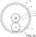
- the transmission T further comprises an annulus internally toothed first ring gear 4a drivingly connected to the second input shaft 1b and an annulus internally toothed second ring gear 4b releasably connected to the first ring gear 4a, as illustrated in figure 1 .
- the first ring gear 4a and the second ring gear 4b are concentrically arranged in relation to each other and separated in the axial direction A.
- the first ring gear 4a and the second ring gear 4b are releasably connected to each other via a first clutch C1.
- the first clutch C1 may be of any suitable type that is selectively operated, allowing the ring gears to either be connected to each other or disconnected from each other depending on the state of the first clutch C1, such as for example a multidisc clutch for a compact transmission design. Due to the relatively large diameters of the first ring gear 4a and the second ring gear 4b, the first clutch C1 may be arranged as a dry clutch. Alternatively, the first clutch C1 is arranged as a wet clutch.
- first ring gear 4a and the second ring gear 4b When the first ring gear 4a and the second ring gear 4b are connected to each other by the first clutch C1, they are rotating as a common unit with the same rotational speed. When the first ring gear 4a and the second ring gear 4b are disconnected from each other, they are free to rotate relative to each other. When disconnected, the ring gears may rotate with the same rotational speed or with different rotational speeds, and further, one of the ring gears may be rotating and the other may be non-rotating, depending on the design and construction of the transmission T. As shown in the embodiment illustrated in the figures, the second ring gear 4b has a larger diameter that the first ring gear 4a. It should however be understood that the ring gears may have other configurations or sizes, such as for example the same diameter, or the first ring gear may instead have a larger diameter.
- the first intermediate shaft 3a and the second intermediate shaft 3b are arranged inside the first ring gear 4a and the second ring gear 4b for a compact layout of the transmission T.
- the first intermediate shaft 3a comprises a first gear wheel 5a in engagement with the first ring gear 4a and a second gear wheel 5b in engagement with the second ring gear 4b.
- the first gear wheel 5a and the second gear wheel 5b are arranged as externally toothed gears for engagement with the respective internally toothed ring gears.
- the second intermediate shaft 3b comprises a third gear wheel 5c in engagement with the first ring gear 4a and a fourth gear wheel 5d in engagement with the second ring gear 4b.
- the third gear wheel 5c and the fourth gear wheel 5d are arranged as externally toothed gears for engagement with the respective internally toothed ring gears.
- the first output shaft 2a comprises a fifth gear wheel 5e in engagement with the second gear wheel 5b
- the second output shaft 2b comprises a sixth gear wheel 5f in engagement with the fourth gear wheel 5d.
- the fifth gear wheel 5e is arranged as an externally toothed gear for engagement with the second gear wheel 5b
- the sixth gear wheel 5f is arranged as an externally toothed gear for engagement with the fourth gear wheel 5d.
- the ring gears and the gear wheels may have any suitable toothed configuration for secure interaction and torque transfer.
- the first gear wheel 5a and the third gear wheel 5c are arranged on radially opposite sides of the first input gear shaft 1a and the first output gear shaft 2a
- the second gear wheel 5b and the fourth gear wheel 5d are arranged on radially opposite sides of the first input gear shaft 1a and the first output gear shaft 2a.
- one example embodiment of the multi-speed transmission is exemplified. It should be understood that the ring gears and the gear wheels could have other configurations or sizes, such as for example other relationships between diameters.
- the first ring gear 4a, the first gear wheel 5a, and the third gear wheel 5c are arranged in a first axial plane P A1 .
- the second ring gear 4b, the second gear wheel 5b, and the fifth gear wheel 5e are arranged in a second axial plane P A2 .
- the second ring gear 4b, the fourth gear wheel 5d, and the sixth gear wheel 5f are arranged in a third axial plane P A3 .
- the first axial plane P A1 , the second axial plane P A2 , and the third axial plane P A3 are spaced apart from each other in the axial direction A.
- the second axial plane P A2 is arranged between the first axial plane P A1 and the third axial plane P A3 .
- the first axial plane P A1 , the second axial plane P A2 , and the third axial plane P A3 are arranged in a parallel relationship to each other and separated in the axial direction A of the transmission T.
- the first intermediate shaft 3a comprises a second clutch C2.
- the second clutch C2 is arranged between the first gear wheel 5a and the second gear wheel 5b.
- the first gear wheel 5a and the second gear wheel 5b may be selectively connected to each other or disconnected from each other depending on the state of the second clutch C2.
- the first gear wheel 5a and the second gear wheel 5b are releasably connected to each other via the second clutch C2.
- the second clutch C2 may be of any suitable design, such as for example a dog clutch, a friction clutch, or a synchronizer clutch assembly. When the second clutch C2 is connected, the first gear wheel 5a and the second gear wheel 5b are rotating in the same rotational direction with the same rotational speed.
- the first gear wheel 5a and the second gear wheel 5b are disconnected from each other and they are free to rotate relative to each other.
- the gear wheels may rotate with the same rotational speed or with different rotational speeds, and further, one of the gearwheels may be rotating and the other may be non-rotating.
- the second intermediate shaft 3b comprises a third clutch C3.
- the third clutch C3 is arranged between the third gear wheel 5c and the fourth gear wheel 5d.
- the third gear wheel 5c and the fourth gear wheel 5d may be selectively connected to each other or disconnected from each other depending on the state of the third clutch C3.
- the third gear wheel 5c and the fourth gear wheel 5d are releasably connected to each other via the third clutch C3.
- the third clutch C3 may be of any suitable design, such as for example a dog clutch, a friction clutch, or a synchronizer clutch assembly. When the third clutch C3 is connected, the third gear wheel 5c and the fourth gear wheel 5d are rotating in the same rotational direction with the same rotational speed.
- the third gear wheel 5c and the fourth gear wheel 5d are disconnected from each other and they are free to rotate relative to each other.
- the gear wheels may rotate with the same rotational speed or with different rotational speeds, and further, one of the gearwheels may be rotating and the other may be non-rotating.
- the multi-speed transmission T may further comprise non-illustrated shafts, bearing structures, housing structures and other components, for enabling the functionality of the transmission.
- the multi-speed transmission T suitably comprises a control unit 6 for controlling the operation of the transmission system, as schematically indicated in for example figure 1 .
- the control unit may control actuators or other components needed for enabling the different operational modes of the transmission T via the clutches.
- the control unit is thus used for selecting the connection or disconnection of the respective clutches, for delivering a correct gear ratio depending on driving conditions of the vehicle.
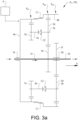
- FIG 3a a layout view of the multi-speed transmission T in a first operational step OS 1 providing a first gear ratio G 1 is schematically illustrated.
- a command may be received from the control unit 6 for operating the transmission T with the first gear ratio G 1 , by: transferring torque from the first input shaft 1a directly to the first output shaft 2a for providing the first gear ratio G 1 .
- the torque transfer path is illustrated with arrows in the figure.
- the first clutch C1, the second clutch C2, and the third clutch C3 may be arranged in any suitable state, since no torque transfer is taking place via the clutches.
- This operational step is providing a driving gear, where the rotational direction of the output shaft is the same as the rotational direction of the input shaft.
- FIG 3b a layout view of the multi-speed transmission T in a second operational step OS 2 providing a second gear ratio G 2 is schematically illustrated.
- a command may be received from the control unit 6 for operating the transmission T with the second gear ratio G 2 , by: connecting the first clutch C1, disconnecting the second clutch C2, and disconnecting the third clutch C3; transferring torque from the second input shaft 1b to the first output shaft 2a via the first ring gear 4a, the second ring gear 4b, the second gear wheel 5b, and the fifth gear wheel 5e, for providing the second gear ratio G 2 .
- the torque transfer path is illustrated with arrows in the figure.
- This operational step is providing a driving gear, where the rotational direction of the output shaft is opposite the rotational direction of the input shaft.
- FIG 3c a layout view of the multi-speed transmission T in a third operational step OS 3 providing a third gear ratio G 3 is schematically illustrated.
- a command may be received from the control unit 6 for operating the transmission T with the third gear ratio G 3 , by: disconnecting the first clutch C1, connecting the second clutch C2, and disconnecting the third clutch C3; transferring torque from the second input shaft 1b to the second output shaft 2b via the first ring gear 4a, the first gear wheel 5a, the second gear wheel 5b, the second ring gear 4b, the fourth gear wheel 5d, and the sixth gear wheel 5f, for providing the third gear ratio G 3 .
- the torque transfer path is illustrated with arrows in the figure.
- This operational step is providing a driving gear, where the rotational direction of the output shaft is opposite the rotational direction of the input shaft.
- FIG 3d a layout view of the multi-speed transmission T in a fourth operational step OS 4 providing a fourth gear ratio G 4 is schematically illustrated.
- a command may be received from the control unit 6 for operating the transmission T with the fourth gear ratio G 4 , by: disconnecting the first clutch C1, connecting the second clutch C2, and disconnecting the third clutch C3; transferring torque from the second input shaft 1b to the first output shaft 2a via the first ring gear 4a, the first gear wheel 5a, the second gear wheel 5b, and the fifth gear wheel 5e for providing the fourth gear ratio G 4 .
- the torque transfer path is illustrated with arrows in the figure.
- This operational step is providing a driving gear, where the rotational direction of the output shaft is opposite the rotational direction of the input shaft.
- FIG 3e a layout view of the multi-speed transmission T in a fifth operational step OS 5 providing a fifth gear ratio G 5 is schematically illustrated.
- a command may be received from the control unit 6 for operating the transmission T with the fifth gear ratio G 5 , by: disconnecting the first clutch C1, disconnecting the second clutch C2, and connecting the third clutch C3; transferring torque from the second input shaft 1b to the second output shaft 2b via the first ring gear 4a, the third gear wheel 5c, the fourth gear wheel 5d, and the sixth gear wheel 5f, for providing the fifth gear ratio G 5 .
- the torque transfer path is illustrated with arrows in the figure.
- This operational step is providing a driving gear, where the rotational direction of the output shaft is opposite the rotational direction of the input shaft.
- FIG 3f a layout view of the multi-speed transmission T in a sixth operational step OS 6 providing a sixth gear ratio G 6 is schematically illustrated.
- a command may be received from the control unit 6 for operating the transmission T with the sixth gear ratio G 6 , by: disconnecting the first clutch C1, disconnecting the second clutch C2, and connecting the third clutch C3; and transferring torque from the second input shaft 1b to the first output shaft 2a via the first ring gear 4a, the third gear wheel 5c, the fourth gear wheel 5d, the second ring gear 4b, the second gear wheel 5b, and the fifth gear wheel 5e, for providing the sixth gear ratio G 6 .
- the torque transfer path is illustrated with arrows in the figure.
- This operational step is providing a driving gear, where the rotational direction of the output shaft is opposite the rotational direction of the input shaft.
- FIG 3g a layout view of the multi-speed transmission T in a seventh operational step OS 7 providing a seventh gear ratio G 7 is schematically illustrated.
- a command may be received from the control unit 6 for operating the transmission T with the seventh gear ratio G 7 , by: connecting the first clutch C1, disconnecting the second clutch C2, and disconnecting the third clutch C3; and transferring torque from the second input shaft 1b to the second output shaft 2b via the first ring gear 4a, the second ring gear 4b, the fourth gear wheel 5d, and the sixth gear wheel 5f, for providing the seventh gear ratio G 7 .
- the torque transfer path is illustrated with arrows in the figure.
- This operational step is providing a driving gear, where the rotational direction of the output shaft is opposite the rotational direction of the input shaft.
- FIG 3h a layout view of the multi-speed transmission T in an eight operational step OS 8 providing an eight gear ratio G 8 is schematically illustrated.
- a command may be received from the control unit 6 for operating the transmission T with the eight gear ratio G 8 , by: disconnecting the first clutch C1, disconnecting the second clutch C2, and disconnecting the third clutch C3; and transferring torque from the first input shaft 1a to the second output shaft 2b via the fifth gear wheel 5e, the second gear wheel 5b, the second ring gear 4b, the fourth gear wheel 5d, and the sixth gear wheel 5f, for providing the eight gear ratio G 8 .
- the torque transfer path is illustrated with arrows in the figure.
- This operational step is providing a driving gear, where the rotational direction of the output shaft is the same as the rotational direction of the input shaft.
- FIG 3i a layout view of the multi-speed transmission T in a ninth operational step OS 9 providing a ninth gear ratio Gg is schematically illustrated.
- a command may be received from the control unit 6 for operating the transmission T with the ninth gear ratio G 9 , by: disconnecting the first clutch C1, connecting the second clutch C2, and connecting the third clutch C3; and transferring torque from the first input shaft 1a to the second output shaft 2b via the fifth gear wheel 5e, the second gear wheel 5b, the first gear wheel 5a, the first ring gear 4a, the third gear wheel 5c, the fourth gear wheel 5d, and the sixth gear wheel 5f, for providing the ninth gear ratio G 9 .
- the torque transfer path is illustrated with arrows in the figure.
- This operational step is providing a driving gear, where the rotational direction of the output shaft is the same as the rotational direction of the input shaft.
- FIG 4 An alternative embodiment of the multi-speed transmission is illustrated in figure 4 .
- the second output shaft 2b of the multi speed transmission T is comprising the sixth gear wheel 5f and further a seventh gear wheel 5g.
- the sixth gear wheel 5f is drivingly engaging the fourth gear wheel 5d in the same way as in the embodiments described above
- the seventh gear wheel 5g is drivingly engaging the fourth gear wheel 5d via an idler gear 7.
- the idler gear 7 is thus arranged between the fourth gear wheel 5d and the seventh gear wheel 5h.
- the sixth gear wheel 5f and the seventh gear wheel 5g are connected to the second output shaft 2b via a fourth clutch C4, where the fourth clutch C4 is selectively connecting the sixth gear wheel 5f or the seventh gear wheel 5g to the second output shaft 2b.
- the fourth clutch C4 is connecting the sixth gear wheel 5f to the second output shaft 2b
- the seventh gear wheel 5g is disconnected from the second output shaft 2b. In this way, the seventh gear wheel 5g is free to rotate about second output shaft 2b when the sixth gear wheel 5f is connected to the second output shaft 2b.
- the fourth clutch C4 When the fourth clutch C4 is connecting the sixth gear wheel 5f to the second output shaft 2b, the second ring gear 4b, the fourth gear wheel 5d, and the sixth gear wheel 5f are forming the third axial plane P A3 .
- the fourth clutch C4 When the fourth clutch C4 is connecting the seventh gear wheel 5g to the second output shaft 2b, the sixth gear wheel 5f is disconnected from the second output shaft 2b. In this way, the sixth gear wheel 5f is free to rotate about second output shaft 2b when the seventh gear wheel 5g is connected to the second output shaft 2b.
- the fourth clutch C4 When the fourth clutch C4 is connecting the seventh gear wheel 5g to the second output shaft 2b, the second ring gear 4b, the fourth gear wheel 5d, the idler gear 7, and the seventh gear wheel 5g are forming the third axial plane P A3 .
- the sixth gear wheel 5f and the seventh gear wheel 5g are connected to the second driving shaft with suitable bearings and a suitable clutch arrangement forming the fourth clutch C4, such as a synchronizing clutch configured for slidingly connect one of the gear wheels to the second output shaft 2b, or other similar clutch arrangement.
- a layout view of the multi-speed transmission T in a tenth operational step OS 10 providing a tenth gear ratio G 10 is schematically illustrated.
- a command may be received from the control unit 6 for operating the transmission T with the tenth gear ratio G 10 , by: disconnecting the first clutch C1, disconnecting the second clutch C2, disconnecting the third clutch C3, and connecting the seventh gear wheel 5g to the second output shaft 2b with the fourth clutch C4; and transferring torque from the first input shaft 1a to the second output shaft 2b via the fifth gear wheel 5e, the second gear wheel 5b, the second ring gear 4b, the fourth gear wheel 5d, the idler gear 7, and the seventh gear wheel 5g, for providing the tenth gear ratio G 10 .
- the torque transfer path is illustrated with arrows in the figure.
- This operational step is providing a driving gear, where the rotational direction of the output shaft is opposite the rotational direction of the input shaft. If instead connecting the sixth gear wheel 5f to the second output shaft 2b with the fourth clutch C4, the transmission T is operated in the same way as illustrated in figure 3h .
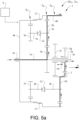
- FIG 5b a layout view of the multi-speed transmission T in an eleventh operational step OS 11 providing an eleventh gear ratio G 11 is schematically illustrated.
- a command may be received from the control unit 6 for operating the transmission T with the eleventh gear ratio G 11 , by: disconnecting the first clutch C1, connecting the second clutch C2, connecting the third clutch C3, and connecting the seventh gear wheel 5g to the second output shaft 2b with the fourth clutch C4; and transferring torque from the first input shaft 1a to the second output shaft 2b via the fifth gear wheel 5e, the second gear wheel 5b, the first gear wheel 5a, the first ring gear 4a, the third gear wheel 5c, the fourth gear wheel 5d, the idler gear 7, and the seventh gear wheel 5g, for providing the eleventh gear ratio G 11 .
- the torque transfer path is illustrated with arrows in the figure.
- This operational step is providing a driving gear, where the rotational direction of the output shaft is opposite the rotational direction of the input shaft. If instead connecting the sixth gear wheel 5f to the second output shaft 2b with the fourth clutch C4, the transmission T is operated in the same way as illustrated in figure 3i .
- a non-transitory computer-readable storage medium storing one or more programs configured to be executed by one or more processors of the transmission system or the control unit of the transmission system, the one or more programs comprising instructions for performing the method according to any one of the above-discussed embodiments.
- a cloud computing system can be configured to perform any of the method aspects presented herein.
- the cloud computing system may comprise distributed cloud computing resources that jointly perform the method aspects presented herein under control of one or more computer program products.
- the processor may be connected to one or more communication interfaces and/or sensor interfaces for receiving and/transmitting data with external entities such as e.g. sensors arranged on the vehicle surface, an off-site server, or a cloud-based server.
- the processor or processors of the transmission system or the control unit associated with the transmission system may be or include any number of hardware components for conducting data or signal processing or for executing computer code stored in memory.
- the system may have an associated memory, and the memory may be one or more devices for storing data and/or computer code for completing or facilitating the various methods described in the present description.
- the memory may include volatile memory or non-volatile memory.
- the memory may include database components, object code components, script components, or any other type of information structure for supporting the various activities of the present description. According to an exemplary embodiment, any distributed or local memory device may be utilized with the systems and methods of this description.
- the memory is communicably connected to the processor (e.g., via a circuit or any other wired, wireless, or network connection) and includes computer code for executing one or more processes described herein.
Landscapes
- Engineering & Computer Science (AREA)
- General Engineering & Computer Science (AREA)
- Mechanical Engineering (AREA)
- Structure Of Transmissions (AREA)
Priority Applications (4)
| Application Number | Priority Date | Filing Date | Title |
|---|---|---|---|
| EP21214870.4A EP4198342B1 (de) | 2021-12-15 | 2021-12-15 | Mehrganggetriebe für ein fahrzeug, fahrzeug und verfahren zum betrieb eines mehrganggetriebes |
| PCT/CN2022/134932 WO2023109498A1 (en) | 2021-12-15 | 2022-11-29 | A multi-speed transmission for a vehicle, a vehicle, and a method for operating a multi-speed transmission |
| CN202280082316.2A CN118401768A (zh) | 2021-12-15 | 2022-11-29 | 用于车辆的多级变速器、车辆和用于操作多级变速器的方法 |
| US18/666,722 US12203535B2 (en) | 2021-12-15 | 2024-05-16 | Multi-speed transmission for a vehicle, a vehicle, and a method for operating a multi-speed transmission |
Applications Claiming Priority (1)
| Application Number | Priority Date | Filing Date | Title |
|---|---|---|---|
| EP21214870.4A EP4198342B1 (de) | 2021-12-15 | 2021-12-15 | Mehrganggetriebe für ein fahrzeug, fahrzeug und verfahren zum betrieb eines mehrganggetriebes |
Publications (2)
| Publication Number | Publication Date |
|---|---|
| EP4198342A1 true EP4198342A1 (de) | 2023-06-21 |
| EP4198342B1 EP4198342B1 (de) | 2025-08-06 |
Family
ID=79024123
Family Applications (1)
| Application Number | Title | Priority Date | Filing Date |
|---|---|---|---|
| EP21214870.4A Active EP4198342B1 (de) | 2021-12-15 | 2021-12-15 | Mehrganggetriebe für ein fahrzeug, fahrzeug und verfahren zum betrieb eines mehrganggetriebes |
Country Status (4)
| Country | Link |
|---|---|
| US (1) | US12203535B2 (de) |
| EP (1) | EP4198342B1 (de) |
| CN (1) | CN118401768A (de) |
| WO (1) | WO2023109498A1 (de) |
Citations (3)
| Publication number | Priority date | Publication date | Assignee | Title |
|---|---|---|---|---|
| JPS63104299U (de) * | 1986-12-26 | 1988-07-06 | ||
| DE19821164A1 (de) * | 1998-05-12 | 1999-11-18 | Volkswagen Ag | Doppelkupplungsgetriebe |
| DE102017223373B4 (de) * | 2017-12-20 | 2019-08-01 | Zf Friedrichshafen Ag | Getriebe und Antriebsstrang umfassend ein Getriebe für einen Außenbordantrieb |
Family Cites Families (6)
| Publication number | Priority date | Publication date | Assignee | Title |
|---|---|---|---|---|
| US4122731A (en) | 1977-03-18 | 1978-10-31 | Gardner-Denver Company | Multispeed gear transmission with plural inputs to internal gear |
| US8425371B2 (en) | 2009-08-05 | 2013-04-23 | GM Global Technology Operations LLC | Multi-speed transmission having three planetary gear sets |
| KR101234641B1 (ko) * | 2010-11-12 | 2013-02-19 | 현대자동차주식회사 | 차량용 자동 변속기의 기어 트레인 |
| KR101496943B1 (ko) | 2011-10-20 | 2015-03-03 | 김영일 | 변속장치 |
| KR101348464B1 (ko) | 2012-11-28 | 2014-01-07 | 현대다이모스(주) | 내접형 변속기 |
| KR102600056B1 (ko) * | 2018-08-22 | 2023-11-07 | 현대자동차 주식회사 | 하이브리드 차량용 동력전달장치 |
-
2021
- 2021-12-15 EP EP21214870.4A patent/EP4198342B1/de active Active
-
2022
- 2022-11-29 WO PCT/CN2022/134932 patent/WO2023109498A1/en not_active Ceased
- 2022-11-29 CN CN202280082316.2A patent/CN118401768A/zh active Pending
-
2024
- 2024-05-16 US US18/666,722 patent/US12203535B2/en active Active
Patent Citations (3)
| Publication number | Priority date | Publication date | Assignee | Title |
|---|---|---|---|---|
| JPS63104299U (de) * | 1986-12-26 | 1988-07-06 | ||
| DE19821164A1 (de) * | 1998-05-12 | 1999-11-18 | Volkswagen Ag | Doppelkupplungsgetriebe |
| DE102017223373B4 (de) * | 2017-12-20 | 2019-08-01 | Zf Friedrichshafen Ag | Getriebe und Antriebsstrang umfassend ein Getriebe für einen Außenbordantrieb |
Also Published As
| Publication number | Publication date |
|---|---|
| EP4198342B1 (de) | 2025-08-06 |
| US20240301941A1 (en) | 2024-09-12 |
| WO2023109498A1 (en) | 2023-06-22 |
| US12203535B2 (en) | 2025-01-21 |
| CN118401768A (zh) | 2024-07-26 |
Similar Documents
| Publication | Publication Date | Title |
|---|---|---|
| US9512905B2 (en) | Multi-speed transmission | |
| US9541168B2 (en) | Multi-speed transmission | |
| US9518638B2 (en) | Multi-speed transmission | |
| US9625007B2 (en) | Multi-speed transmission | |
| US20160116027A1 (en) | Multi-speed transmission | |
| US9927009B2 (en) | Multi-speed transmission | |
| US20160040754A1 (en) | Multi-speed transmission | |
| US20170016516A1 (en) | Multi-speed transmission | |
| EP3487723B1 (de) | Schubkraftunterdrückung bei einem zapfwellenantrieb | |
| CN104595433A (zh) | 多级变速器 | |
| US20180223966A1 (en) | Multi-speed transmission | |
| US10344836B2 (en) | Vehicle transmission | |
| KR102474801B1 (ko) | 전기 자동차용 2단 변속기 | |
| EP3193042B1 (de) | Doppelkupplungsgetriebe | |
| EP4198342B1 (de) | Mehrganggetriebe für ein fahrzeug, fahrzeug und verfahren zum betrieb eines mehrganggetriebes | |
| US10309492B2 (en) | Planetary gear train of automatic transmission for vehicle | |
| US10480623B2 (en) | Automatic transmission for a vehicle | |
| US11703124B2 (en) | Actuator system for a vehicle transmission, a vehicle comprising an actuator system, and a method for operating an actuator system | |
| US9810287B2 (en) | Multi-speed transmission | |
| US20190085947A1 (en) | Planetary Gear Train of Automatic Transmission for Vehicles | |
| US11320033B2 (en) | Differential assembly for shifting | |
| US20170067544A1 (en) | Multi-speed transmission | |
| US10330177B2 (en) | Planetary gear train of automatic transmission for vehicle | |
| JPH07280046A (ja) | 入力方向により速度比をコントロールする差動歯車機構 | |
| JP2018168931A (ja) | 変速機 |
Legal Events
| Date | Code | Title | Description |
|---|---|---|---|
| PUAI | Public reference made under article 153(3) epc to a published international application that has entered the european phase |
Free format text: ORIGINAL CODE: 0009012 |
|
| STAA | Information on the status of an ep patent application or granted ep patent |
Free format text: STATUS: REQUEST FOR EXAMINATION WAS MADE |
|
| 17P | Request for examination filed |
Effective date: 20211215 |
|
| AK | Designated contracting states |
Kind code of ref document: A1 Designated state(s): AL AT BE BG CH CY CZ DE DK EE ES FI FR GB GR HR HU IE IS IT LI LT LU LV MC MK MT NL NO PL PT RO RS SE SI SK SM TR |
|
| GRAP | Despatch of communication of intention to grant a patent |
Free format text: ORIGINAL CODE: EPIDOSNIGR1 |
|
| STAA | Information on the status of an ep patent application or granted ep patent |
Free format text: STATUS: GRANT OF PATENT IS INTENDED |
|
| INTG | Intention to grant announced |
Effective date: 20250310 |
|
| GRAS | Grant fee paid |
Free format text: ORIGINAL CODE: EPIDOSNIGR3 |
|
| GRAA | (expected) grant |
Free format text: ORIGINAL CODE: 0009210 |
|
| STAA | Information on the status of an ep patent application or granted ep patent |
Free format text: STATUS: THE PATENT HAS BEEN GRANTED |
|
| AK | Designated contracting states |
Kind code of ref document: B1 Designated state(s): AL AT BE BG CH CY CZ DE DK EE ES FI FR GB GR HR HU IE IS IT LI LT LU LV MC MK MT NL NO PL PT RO RS SE SI SK SM TR |
|
| REG | Reference to a national code |
Ref country code: GB Ref legal event code: FG4D |
|
| REG | Reference to a national code |
Ref country code: CH Ref legal event code: EP |
|
| REG | Reference to a national code |
Ref country code: IE Ref legal event code: FG4D |
|
| REG | Reference to a national code |
Ref country code: DE Ref legal event code: R096 Ref document number: 602021035511 Country of ref document: DE |
|
| REG | Reference to a national code |
Ref country code: NL Ref legal event code: MP Effective date: 20250806 |
|
| PG25 | Lapsed in a contracting state [announced via postgrant information from national office to epo] |
Ref country code: IS Free format text: LAPSE BECAUSE OF FAILURE TO SUBMIT A TRANSLATION OF THE DESCRIPTION OR TO PAY THE FEE WITHIN THE PRESCRIBED TIME-LIMIT Effective date: 20251206 |
|
| PGFP | Annual fee paid to national office [announced via postgrant information from national office to epo] |
Ref country code: DE Payment date: 20251104 Year of fee payment: 5 |
|
| PGFP | Annual fee paid to national office [announced via postgrant information from national office to epo] |
Ref country code: GB Payment date: 20251114 Year of fee payment: 5 |
|
| PG25 | Lapsed in a contracting state [announced via postgrant information from national office to epo] |
Ref country code: NO Free format text: LAPSE BECAUSE OF FAILURE TO SUBMIT A TRANSLATION OF THE DESCRIPTION OR TO PAY THE FEE WITHIN THE PRESCRIBED TIME-LIMIT Effective date: 20251106 |
|
| REG | Reference to a national code |
Ref country code: LT Ref legal event code: MG9D |
|
| PG25 | Lapsed in a contracting state [announced via postgrant information from national office to epo] |
Ref country code: PT Free format text: LAPSE BECAUSE OF FAILURE TO SUBMIT A TRANSLATION OF THE DESCRIPTION OR TO PAY THE FEE WITHIN THE PRESCRIBED TIME-LIMIT Effective date: 20251209 |
|
| PG25 | Lapsed in a contracting state [announced via postgrant information from national office to epo] |
Ref country code: FI Free format text: LAPSE BECAUSE OF FAILURE TO SUBMIT A TRANSLATION OF THE DESCRIPTION OR TO PAY THE FEE WITHIN THE PRESCRIBED TIME-LIMIT Effective date: 20250806 |
|
| PG25 | Lapsed in a contracting state [announced via postgrant information from national office to epo] |
Ref country code: NL Free format text: LAPSE BECAUSE OF FAILURE TO SUBMIT A TRANSLATION OF THE DESCRIPTION OR TO PAY THE FEE WITHIN THE PRESCRIBED TIME-LIMIT Effective date: 20250806 Ref country code: HR Free format text: LAPSE BECAUSE OF FAILURE TO SUBMIT A TRANSLATION OF THE DESCRIPTION OR TO PAY THE FEE WITHIN THE PRESCRIBED TIME-LIMIT Effective date: 20250806 |
|
| PGFP | Annual fee paid to national office [announced via postgrant information from national office to epo] |
Ref country code: FR Payment date: 20251117 Year of fee payment: 5 |
|
| PG25 | Lapsed in a contracting state [announced via postgrant information from national office to epo] |
Ref country code: SE Free format text: LAPSE BECAUSE OF FAILURE TO SUBMIT A TRANSLATION OF THE DESCRIPTION OR TO PAY THE FEE WITHIN THE PRESCRIBED TIME-LIMIT Effective date: 20250806 |
|
| PG25 | Lapsed in a contracting state [announced via postgrant information from national office to epo] |
Ref country code: LV Free format text: LAPSE BECAUSE OF FAILURE TO SUBMIT A TRANSLATION OF THE DESCRIPTION OR TO PAY THE FEE WITHIN THE PRESCRIBED TIME-LIMIT Effective date: 20250806 |
|
| PG25 | Lapsed in a contracting state [announced via postgrant information from national office to epo] |
Ref country code: PL Free format text: LAPSE BECAUSE OF FAILURE TO SUBMIT A TRANSLATION OF THE DESCRIPTION OR TO PAY THE FEE WITHIN THE PRESCRIBED TIME-LIMIT Effective date: 20250806 Ref country code: BG Free format text: LAPSE BECAUSE OF FAILURE TO SUBMIT A TRANSLATION OF THE DESCRIPTION OR TO PAY THE FEE WITHIN THE PRESCRIBED TIME-LIMIT Effective date: 20250806 |
|
| PG25 | Lapsed in a contracting state [announced via postgrant information from national office to epo] |
Ref country code: RS Free format text: LAPSE BECAUSE OF FAILURE TO SUBMIT A TRANSLATION OF THE DESCRIPTION OR TO PAY THE FEE WITHIN THE PRESCRIBED TIME-LIMIT Effective date: 20251106 |
|
| PG25 | Lapsed in a contracting state [announced via postgrant information from national office to epo] |
Ref country code: ES Free format text: LAPSE BECAUSE OF FAILURE TO SUBMIT A TRANSLATION OF THE DESCRIPTION OR TO PAY THE FEE WITHIN THE PRESCRIBED TIME-LIMIT Effective date: 20250806 |
|
| REG | Reference to a national code |
Ref country code: AT Ref legal event code: MK05 Ref document number: 1822151 Country of ref document: AT Kind code of ref document: T Effective date: 20250806 |
|
| PG25 | Lapsed in a contracting state [announced via postgrant information from national office to epo] |
Ref country code: RO Free format text: LAPSE BECAUSE OF FAILURE TO SUBMIT A TRANSLATION OF THE DESCRIPTION OR TO PAY THE FEE WITHIN THE PRESCRIBED TIME-LIMIT Effective date: 20250806 |
|
| PG25 | Lapsed in a contracting state [announced via postgrant information from national office to epo] |
Ref country code: SM Free format text: LAPSE BECAUSE OF FAILURE TO SUBMIT A TRANSLATION OF THE DESCRIPTION OR TO PAY THE FEE WITHIN THE PRESCRIBED TIME-LIMIT Effective date: 20250806 |
|
| PG25 | Lapsed in a contracting state [announced via postgrant information from national office to epo] |
Ref country code: DK Free format text: LAPSE BECAUSE OF FAILURE TO SUBMIT A TRANSLATION OF THE DESCRIPTION OR TO PAY THE FEE WITHIN THE PRESCRIBED TIME-LIMIT Effective date: 20250806 |
|
| PG25 | Lapsed in a contracting state [announced via postgrant information from national office to epo] |
Ref country code: AT Free format text: LAPSE BECAUSE OF FAILURE TO SUBMIT A TRANSLATION OF THE DESCRIPTION OR TO PAY THE FEE WITHIN THE PRESCRIBED TIME-LIMIT Effective date: 20250806 |
|
| PG25 | Lapsed in a contracting state [announced via postgrant information from national office to epo] |
Ref country code: IT Free format text: LAPSE BECAUSE OF FAILURE TO SUBMIT A TRANSLATION OF THE DESCRIPTION OR TO PAY THE FEE WITHIN THE PRESCRIBED TIME-LIMIT Effective date: 20250806 |