EP4208069B1 - Filterpatrone - Google Patents
Filterpatrone Download PDFInfo
- Publication number
- EP4208069B1 EP4208069B1 EP21769468.6A EP21769468A EP4208069B1 EP 4208069 B1 EP4208069 B1 EP 4208069B1 EP 21769468 A EP21769468 A EP 21769468A EP 4208069 B1 EP4208069 B1 EP 4208069B1
- Authority
- EP
- European Patent Office
- Prior art keywords
- filter
- filter cartridge
- circle
- wall
- tank
- Prior art date
- Legal status (The legal status is an assumption and is not a legal conclusion. Google has not performed a legal analysis and makes no representation as to the accuracy of the status listed.)
- Active
Links
Images


Classifications
-
- A—HUMAN NECESSITIES
- A47—FURNITURE; DOMESTIC ARTICLES OR APPLIANCES; COFFEE MILLS; SPICE MILLS; SUCTION CLEANERS IN GENERAL
- A47J—KITCHEN EQUIPMENT; COFFEE MILLS; SPICE MILLS; APPARATUS FOR MAKING BEVERAGES
- A47J31/00—Apparatus for making beverages
- A47J31/44—Parts or details or accessories of beverage-making apparatus
- A47J31/60—Cleaning devices
- A47J31/605—Water filters
-
- B—PERFORMING OPERATIONS; TRANSPORTING
- B01—PHYSICAL OR CHEMICAL PROCESSES OR APPARATUS IN GENERAL
- B01D—SEPARATION
- B01D27/00—Cartridge filters of the throw-away type
- B01D27/08—Construction of the casing
-
- B—PERFORMING OPERATIONS; TRANSPORTING
- B01—PHYSICAL OR CHEMICAL PROCESSES OR APPARATUS IN GENERAL
- B01D—SEPARATION
- B01D29/00—Filters with filtering elements stationary during filtration, e.g. pressure or suction filters, not covered by groups B01D24/00 - B01D27/00; Filtering elements therefor
- B01D29/11—Filters with filtering elements stationary during filtration, e.g. pressure or suction filters, not covered by groups B01D24/00 - B01D27/00; Filtering elements therefor with bag, cage, hose, tube, sleeve or like filtering elements
- B01D29/114—Filters with filtering elements stationary during filtration, e.g. pressure or suction filters, not covered by groups B01D24/00 - B01D27/00; Filtering elements therefor with bag, cage, hose, tube, sleeve or like filtering elements arranged for inward flow filtration
-
- B—PERFORMING OPERATIONS; TRANSPORTING
- B01—PHYSICAL OR CHEMICAL PROCESSES OR APPARATUS IN GENERAL
- B01D—SEPARATION
- B01D29/00—Filters with filtering elements stationary during filtration, e.g. pressure or suction filters, not covered by groups B01D24/00 - B01D27/00; Filtering elements therefor
- B01D29/96—Filters with filtering elements stationary during filtration, e.g. pressure or suction filters, not covered by groups B01D24/00 - B01D27/00; Filtering elements therefor in which the filtering elements are moved between filtering operations; Particular measures for removing or replacing the filtering elements; Transport systems for filters
-
- B—PERFORMING OPERATIONS; TRANSPORTING
- B01—PHYSICAL OR CHEMICAL PROCESSES OR APPARATUS IN GENERAL
- B01D—SEPARATION
- B01D35/00—Filtering devices having features not specifically covered by groups B01D24/00 - B01D33/00, or for applications not specifically covered by groups B01D24/00 - B01D33/00; Auxiliary devices for filtration; Filter housing constructions
- B01D35/02—Filters adapted for location in special places, e.g. pipe-lines, pumps, stop-cocks
- B01D35/027—Filters adapted for location in special places, e.g. pipe-lines, pumps, stop-cocks rigidly mounted in or on tanks or reservoirs
- B01D35/0276—Filtering elements with a vertical rotation or symmetry axis mounted on tanks or reservoirs
-
- B—PERFORMING OPERATIONS; TRANSPORTING
- B01—PHYSICAL OR CHEMICAL PROCESSES OR APPARATUS IN GENERAL
- B01D—SEPARATION
- B01D35/00—Filtering devices having features not specifically covered by groups B01D24/00 - B01D33/00, or for applications not specifically covered by groups B01D24/00 - B01D33/00; Auxiliary devices for filtration; Filter housing constructions
- B01D35/14—Safety devices specially adapted for filtration; Devices for indicating clogging
- B01D35/153—Anti-leakage or anti-return valves
-
- C—CHEMISTRY; METALLURGY
- C02—TREATMENT OF WATER, WASTE WATER, SEWAGE, OR SLUDGE
- C02F—TREATMENT OF WATER, WASTE WATER, SEWAGE, OR SLUDGE
- C02F1/00—Treatment of water, waste water, or sewage
- C02F1/001—Processes for the treatment of water whereby the filtration technique is of importance
- C02F1/003—Processes for the treatment of water whereby the filtration technique is of importance using household-type filters for producing potable water, e.g. pitchers, bottles, faucet mounted devices
-
- C—CHEMISTRY; METALLURGY
- C02—TREATMENT OF WATER, WASTE WATER, SEWAGE, OR SLUDGE
- C02F—TREATMENT OF WATER, WASTE WATER, SEWAGE, OR SLUDGE
- C02F1/00—Treatment of water, waste water, or sewage
- C02F1/28—Treatment of water, waste water, or sewage by sorption
- C02F1/283—Treatment of water, waste water, or sewage by sorption using coal, charred products, or inorganic mixtures containing them
-
- B—PERFORMING OPERATIONS; TRANSPORTING
- B01—PHYSICAL OR CHEMICAL PROCESSES OR APPARATUS IN GENERAL
- B01D—SEPARATION
- B01D2201/00—Details relating to filtering apparatus
- B01D2201/40—Special measures for connecting different parts of the filter
- B01D2201/4023—Means for connecting filter housings to supports
-
- B—PERFORMING OPERATIONS; TRANSPORTING
- B01—PHYSICAL OR CHEMICAL PROCESSES OR APPARATUS IN GENERAL
- B01D—SEPARATION
- B01D2201/00—Details relating to filtering apparatus
- B01D2201/40—Special measures for connecting different parts of the filter
- B01D2201/4046—Means for avoiding false mounting of different parts
- B01D2201/4053—Means for avoiding false mounting of different parts using keys
-
- C—CHEMISTRY; METALLURGY
- C02—TREATMENT OF WATER, WASTE WATER, SEWAGE, OR SLUDGE
- C02F—TREATMENT OF WATER, WASTE WATER, SEWAGE, OR SLUDGE
- C02F2201/00—Apparatus for treatment of water, waste water or sewage
- C02F2201/002—Construction details of the apparatus
- C02F2201/004—Seals, connections
-
- C—CHEMISTRY; METALLURGY
- C02—TREATMENT OF WATER, WASTE WATER, SEWAGE, OR SLUDGE
- C02F—TREATMENT OF WATER, WASTE WATER, SEWAGE, OR SLUDGE
- C02F2201/00—Apparatus for treatment of water, waste water or sewage
- C02F2201/002—Construction details of the apparatus
- C02F2201/006—Cartridges
-
- C—CHEMISTRY; METALLURGY
- C02—TREATMENT OF WATER, WASTE WATER, SEWAGE, OR SLUDGE
- C02F—TREATMENT OF WATER, WASTE WATER, SEWAGE, OR SLUDGE
- C02F2307/00—Location of water treatment or water treatment device
- C02F2307/10—Location of water treatment or water treatment device as part of a potable water dispenser, e.g. for use in homes or offices
-
- C—CHEMISTRY; METALLURGY
- C02—TREATMENT OF WATER, WASTE WATER, SEWAGE, OR SLUDGE
- C02F—TREATMENT OF WATER, WASTE WATER, SEWAGE, OR SLUDGE
- C02F2307/00—Location of water treatment or water treatment device
- C02F2307/12—Location of water treatment or water treatment device as part of household appliances such as dishwashers, laundry washing machines or vacuum cleaners
Definitions
- the invention relates to a filter cartridge according to the preamble of claim 1.
- Filter cartridges are regularly used in water-carrying household machines with a water tank, especially in beverage machines such as coffee machines, tea machines, etc., to improve the water quality in accordance with the intended application.
- Filter media for water softening such as ion exchange resin, or for taste improvement, such as activated carbon, are often used in such filter cartridges.
- the dosed addition of additives, e.g. for health or taste improvement, such as the addition of minerals or vitamins, etc., is already provided for in combination with filter media.
- Water tanks of such machines regularly have tank connection elements on the tank bottom with an annular tank sealing surface for the tight connection of a filter connection element of the filter cartridge provided for such a water tank, which enclose a tank passage opening in the tank bottom for the flow of water from the filter cartridge and the water tank to the household machine.
- the tank connection elements In order to prevent unsuitable filter cartridges from being used, the tank connection elements have already been provided with coding elements so that only filter cartridges that match these coding elements can be used.
- connection device for permanent connection to a tank bottom, which has pocket-shaped connecting elements for connection to the tank bottom. These are connected with tank-side fixing means in such a way that they can no longer be removed from the tank without causing damage. A filter cartridge can then be inserted into this connection device in an exchangeable manner, the connection device and the filter cartridge having hexagonal coding structures.
- the object of the invention is therefore to further develop such a filter cartridge in such a way that the aforementioned disadvantages are avoided and the fixation of the filter cartridge is improved.
- a filter cartridge according to the invention is provided with a filter housing, the wall of which separates an inside of the housing from an outside of the housing, wherein an open filter inlet opening is provided for the entry of water from the water supply without further connection elements, which is accordingly connected to the inside of the tank when used in a water tank in the operating position of the filter cartridge.
- a device for conducting water is provided in the interior of the filter housing following the filter inlet opening, which comprises at least one filter chamber having at least one filter medium and ends in a filter outlet opening for sucking water out of the filter cartridge.
- a filter connection element is provided with an annular filter connection piece, which has an annular filter fixing surface for fixing relative to a tank-side tank fixing surface.
- such a filter cartridge differs from filter cartridges of filter devices whose housings are tightly connected to water pipes of a water network with pressure-resistant connections and are thus integrated into the water network.
- a filter cartridge according to the invention is provided with a filter fixing surface, the course of which along the circumference of the annular filter connection piece has a varying radius with respect to a central axis, so that the filter fixing surface comprises radial bulges and/or radial indentations, wherein the bulges and/or indentations have a round course, so that corners or edges are avoided.
- This form of filter fixing surface fits onto a corresponding form of tank fixing surface, whereby the curvatures that change from outside to inside and vice versa along the circumference make it difficult or even impossible to clamp a seal that is not adapted in shape onto a fixed tank-side contact surface.
- the shape of the filter fixing surface according to the invention facilitates deformation of the filter connection piece in the area of the filter fixing surface, since the radial bulges and/or indentations form the shape of an annular spring, the circumference of which can be expanded or compressed in a resilient manner.
- Such deformation facilitated by the varying radius, makes it possible to improve the mechanical clamping and thus the fixing, for example in comparison with a circular shape or a polygonal shape.
- This filter fixing surface is advantageously also provided as a filter sealing surface.
- the spring effect of the ring spring also improves the sealing effect, since the spring pressure presses the filter sealing surface flat against the associated tank sealing surface. Since the described shape of the filter fixing surface also avoids corners or edges, this shape improves the sealing function in addition to the spring effect.
- the resilient deformability of the filter fixing surface can be improved by the ring-shaped filter connection piece of the filter connection element having the filter fixing surface having an annular wall with an inner wall side and an outer wall side in the area of the filter fixing surface, which parallel or inclined to each other.
- the outside and/or the inside of the annular wall encloses or forms the filter fixing surface.
- this wall is designed as a ring spring overall.
- the ring-shaped wall then forms a ring spring with parallel or mutually inclined circumferential sides.
- the ring-shaped filter connection piece of the filter connection element can have an outer and/or an inner wall that is beveled relative to the vertical, so that the outer wall and the inner wall converge from top to bottom with respect to the operating position of the filter cartridge.
- the bevelled outer wall can have an outer and/or the bevelled inner wall can have an inner filter fixing surface in order to form a fixing and, if necessary, sealing positive connection with the corresponding tank sealing surface.
- the arrangement of the bulges and indentations of the filter fixing surface is rotationally symmetrical over the circumference. This results in a return force of the ring spring that is evenly distributed around the circumference, with a more stable fixation and sealing of the filter cartridge in the installed position.
- a rotationally symmetrical design of the filter fixing surface is achieved when the bulges and/or indentations are designed to oscillate periodically around a circular line. This allows different angular positions of the filter cartridge, which makes it easier to connect.
- other technical functions can also be provided depending on the angle.
- a more stable fixation of the filter cartridge in the installation position is achieved by arranging the bulges and indentations of the filter fixing surface at equal angles around the circumference.
- the ring spring formed in this way can deform evenly around the circumference in both the area of the bulges and the area of the indentations.
- the bulges and indentations of the filter fixing surface can form a wave shape along a circular line, whereby the wave shape consists of an alternating sequence of convex circular segments forming the bulges and concave circular segments forming the indentations.
- the course following a circular line results in a radially directed spring effect.
- the spring effect of the ring spring can be further improved if the concave and convex circular segments are tangentially connected at turning points at the transition between concave and convex curvatures.
- the arc length of the convex circle segments is longer than the arc length of the concave circle segments.
- the swept angle of the convex The angle of the circular segments is therefore larger than the angle of the concave circular segments.
- the convex and concave circle segments have the same segment radius. This results in a comparable force distribution within the segments during deformation.
- the circle segments can be arranged so that the convex and concave circle segments lie within an outer enveloping circle and outside an inner enveloping circle, with the circle centers of the convex circle segments lying within the inner enveloping circle and the circle centers of the concave circle centers lying outside the outer enveloping circle.
- This shape results in a flat course compared to the enveloping circles or a center line between the enveloping circles, which makes it easier to expand or shrink the ring spring.
- the radius of the convex and/or concave circle segments is between 20% and 35% of the radius of the outer enveloping circle.
- the spring effect of such a spring ring is further enhanced if the wall thickness between the outside of the wall and the inner wall running parallel or inclined to it is between 7% and 10% of the radius of the outer enveloping circle.
- the filter fixing surface can form an outer surface of the annular filter connection piece of the filter connection element, which faces away from a central axis of the filter outlet opening.
- a filter connection piece is able to exert a resilient contact pressure outwards essentially over the entire circumference when inserted into a water tank-side opening with a correspondingly radially inward-facing tank fixing surface in order to achieve the desired fixing effect.
- a resilient contact pressure inwards can be exerted essentially over the entire circumference by a radially inward-facing filter fixing surface in order to achieve the desired fixing effect.
- a filter fixing surface is provided on both the inside and the outside of the filter connection piece, one or both of which simultaneously form a filter sealing surface.
- a filter connection piece can be introduced into a tank-side ring slot, the side walls of which each form a tank fixing surface and/or tank sealing surface.
- the annular filter connection piece of the filter connection element having the filter fixing surface consists, at least in the region of at least one filter fixing surface provided as a filter sealing surface, of a plastic that is more dimensionally stable at operating temperature than an elastomer.
- the filter connection piece of the filter cartridge is still able to exert a spring-loaded contact pressure on a tank-side tank fixing surface via the filter fixing surface in order to ensure that the filter cartridge is firmly seated.
- a fixation can take place, for example, on the inside and/or outside of the filter connection piece.
- such a filter connection piece can easily deform an elastomer seal on the water tank side so that it fits tightly against the filter fixing surface that forms the filter sealing surface. This deformation could also take place on the inside and/or outside of the filter connection piece.
- a deformable elastomer seal is provided either inside or outside or is designed in such a way that it has an annular slot into which the filter connection piece can be inserted.
- one or more other functions can be achieved in addition to the fixing and sealing functions.
- This can, for example, be a hydraulic function, such as a valve function or the like.
- the sealing effect of the filter sealing surface with the tank sealing surface is improved as above if the bulges and/or indentations have a rounded shape so that corners or edges are avoided.
- a constellation that works very well has been shown to include six bulges and six indentations along a circular line with a diameter of less than 3 cm.
- the filter inlet opening of the filter cartridge can be designed as an annular sieve opening on the outside of the filter connection piece, whereby the filter cartridge in the water tank is open to the water contained therein.
- the filter cartridge is improved if a guide structure is provided within the filter connection piece to guide and accommodate a centering element on the water tank side. This allows the filter cartridge to be aligned in the axial direction when inserted into the associated water tank and to be fixed in this alignment in the operating position.
- the filter cartridge can be guided into at least one angular position with the axial movement when inserted into the water tank and can be additionally fixed there via this guide structure in interaction with the associated centering element on the water tank side.
- the guide structure can have several guide grooves distributed around the circumference.
- the filter cartridge can be guided well into the desired angular position if the wall of the guide grooves is rounded in such a way that the width of the groove tapers from bottom to top in relation to the operating position.
- the guidance of the filter cartridge can also be improved if the wall of the guide grooves is rounded in such a way that the width of the groove tapers radially from the inside to the outside.
- the combination of the two tapered groove shapes results in a kind of funnel effect for a rib of a centering element on the water tank side that enters such a groove.
- the groove shapes mentioned can be formed, for example, by means of internal curvatures in a wall of the guide structure connecting the guide grooves.
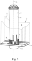
- Fig.1 illustrates the usual design of a water tank 1 of a drinks machine, such as a coffee machine, e.g. a fully automatic coffee machine according to the state of the art.
- the water tank 1 comprises a tank base 2 and water tank side walls 3, partially shown with dashed lines.
- a filter cartridge 4 with a filter housing 5 is inserted into the water tank 1.
- the connection between the tank base 2 and the filter cartridge 4 is realized via tank connection elements 6 on the water tank side and filter connection elements 7 on the filter side.
- the filter cartridge 4 is located in the interior 8 of the water tank 1, ie during operation it is completely or partially immersed in the water stored in the water tank 1.
- a round section of the tank bottom 2 is shown, with a fastening ring 10 and a centering element 11 being provided for insertion into a recess 12 of the tank bottom 2.
- the fastening ring 10 also carries an elastomer seal 16.
- the fastening ring 10 and the centering element 11 are installed in the tank bottom 2.
- the pins 15 can penetrate the centering element and thus form coding elements for coding the water tank relative to the associated machine connection, from which the tank valve body 13 must be actuated when inserting the water tank.
- the elastomer seal 16 forming the water tank seal 17 is a ring seal which has a varying radius R along its circumference relative to a central axis A, so that the inner surface of the water tank seal 17 forming a tank sealing surface 18 comprises radial indentations 19 and radial bulges 20.
- the first tank sealing surface 18 also serves as the first tank fixing surface.
- FIG.5 the connection area 21 of a suitable filter cartridge 22 is shown.
- a filter connection piece 23 forms an inner ring which is surrounded by an outer ring 24 with axially extending projections 25 and recesses 26. Between the inner ring 23 and the outer ring 24 there is an annular inlet screen 27 through which water enters the filter cartridge.
- the outer surface 28 and the inner surface 68 of the filter connection piece 23 are also provided with bulges 29 and indentations 30 to match the tank sealing surface 18.
- the outer surface 28 and/or the inner surface 68 of the filter connection piece 23 can also serve as a filter fixing surface.
- a guide structure 31 of the filter cartridge 22 for receiving the centering element 11 is shown.
- the guide structure has guide grooves 32 which are aligned with the edges 33 of a polygon ring 34, in this case with six guide grooves aligned with six edges of a hexagonal ring.
- the cutting plane passes through this polygon ring 34.
- inner curvatures 35 which lie between the edges 33 and the guide grooves 32.
- the inner curvatures 35 form the side walls 36 of the guide grooves 32. Due to this curved shape, the walls 36 of the guide grooves 32 taper both in the axial direction upwards (relative to the operating position) and in the radial direction from the inside to the outside. In the interface, viewed from above according to Fig.8 the cutting plane runs at a height at which the guide grooves 32 are clearly formed.
- a riser pipe 37 is connected centrally inside, through which the water entering the filter cartridge 22 is guided upwards to the filter section.
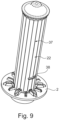
- Fig.9 the entire filter cartridge 22 is shown.
- a filter housing 37 which has an optional lateral dosing opening 38 and the described bottom-side water connection.
- the optional dosing opening 38 is only provided in the case of a design of the filter cartridge which is designed for the dispensing of additives, e.g. minerals, vitamins or the like, from a dosing chamber housed in the filter housing 37 into the water supply. Since such a dosing chamber within the filter housing 37 is closed to the filter section, it has no further significance with regard to filtration.
- a filter cartridge according to the invention can therefore also be designed without this dosing chamber and its dosing opening 38.
- the operating position to which the information above and below in this description refers is recognizable.
- Fig.10 a perspective view of the centering element 11 can be seen.
- the centering element is provided with a base plate 39 which, when mounted, lies in a receptacle of the elastomer seal and engages behind the edge of the latter.
- a centering mandrel 40 protrudes upwards from the base plate 39 and has an annular outer surface 41 which also forms a second tank fixing surface.
- This outer surface 41 has a radius that varies along the circumference relative to the central axis A, so that this outer surface 41 also includes radial indentations 42 and bulges 43.
- the outer surface 41 is thus adapted to a corresponding shape of the filter connection piece 9.
- the indentations 42 and protrusions 43 of this outer surface 41 are also designed to oscillate periodically around a circular line and have a rounded shape.
- six indentations 42 and six protrusions 43 are provided along a circular line with a diameter of less than 3 cm, in accordance with the design of the embodiment shown of the filter cartridge 22.
- the adjustment of the outer surface 41 is or the second tank fixing surface accordingly.
- All adjustments to the outer surface 41 of the centering mandrel 11 mean that, when installed, only an annular slot between the outer surface 41 and the elastomer seal 16 is open for inserting the filter connection piece 23. This provides further protection against the use of an unsuitable filter cartridge. In addition, this makes it possible to support the filter connection piece 23 on its inside on the outer surface 41 of the centering mandrel 11. In this way, the contact pressure of the filter connection piece on the elastomer seal 16 can be increased evenly over the entire circumferential shape using the varying shape.
- At least one upwardly projecting tooth 44 is provided above the annular outer surface.
- the one or more teeth 44 are attached to a step 45 of the centering mandrel 40.
- Further elevations 46 which follow the shape of the outer surface 41, opposite the step 45 are attached at a distance from the teeth 44 so that a gap 47 remains between the teeth and the elevations 46.
- the tooth or teeth 44 and/or the elevations 46 can prevent the use of an axial seal to bypass the coding.
- a passage opening 48 is also provided which, when the centering element 11 is mounted, leads to a tank passage opening. The filtered water of a filter cartridge 22 can be drained from the water tank through this passage opening 48.
- One or more bottom openings 49 are provided below the outer surface 41 in the base plate 39. Unfiltered water from the water tank can flow through these bottom openings. Below the elevations 46 and within the wall supporting the outer surface 41, there is a cavity 50 for receiving the tank valve body 13.
- guide ribs 51 are provided, which can be bevelled on their upper side as in the embodiment shown.
- the guide bevels 52 thus formed help to insert the guide ribs 51 into the guide grooves 32 of a filter cartridge 22.
- the guide bevels 52 of the guide ribs 51 in the attached filter cartridge 22 are clearly visible.
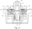
- FIG. 11 , 11a , 11b , 12 and 12a the assembled components of the water tank 1 for connecting a filter cartridge without and with filter cartridge 22 are shown.
- the fastening ring 10 is provided with a locking projection 53 with which it can lock onto the tank base 2 by engaging behind a base rib 54 of the water tank.
- the elastomer seal 16 has a base section 55 which engages under the fastening ring 10 and thus holds the elastomer seal 16 with the fastening ring 10 on the tank base 2.
- the elastomer seal 16 has a sealing surface, which in this case is implemented by a sealing bead 56.
- a circumferential sealing surface can be provided at various points.
- a ring seal 57 is provided which is formed on top of the elastomer seal 16 and seals with the fastening ring in a sealing groove 58 of the latter.
- the elastomer seal 16 comprises an outer ring 59 and an inner ring 60, which are formed and connected in one piece.
- the outer ring 59 and the inner ring 60 both follow in their shape along the circumference the varying radius of the fastening ring 10, the filter connection piece 23 and the elastomer seal 16 and the indentations and bulges formed thereby.
- the outer ring 59 is stepped and carries the ring seal 57 and the sealing bead 56.
- the outer ring 59 is also provided with one or more bypass openings 61 through which unfiltered water can enter the annular gap 62 between the outer ring 59 and the inner ring 60 in the flow direction P1.
- the bypass opening 61 of the elastomer seal 16 is located in the assembled state immediately adjacent to a bypass opening 63 in the fastening ring 11, which can also be found in the Fig.1 and 3 can be seen. Unfiltered water from the annular gap 62 from the water tank 1 can flow through the bypass opening 63 in the direction of P2 into the corresponding beverage machine.
- the inner ring 60 has a sealing lip 64 on its underside, which is opposite a sealing surface 65 on the outer ring 59.
- the annular gap 62 between the outer ring 59 and the inner ring 60 is open at the bottom, as in Fig. 11 can be seen, so that the unfiltered water guided in the bypass can flow out of the annular gap 62 in the flow direction P2.
- the inner side 66 of the inner ring 60 which forms the water tank seal 17, is bevelled inwards as it runs downwards.
- the design of the bypass is shown in the enlargements according to the Fig. 11a and b are highlighted.
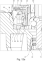
- the elastomer seal 16 When inserting a filter cartridge 22 with the filter connection piece 23, the elastomer seal 16 is deformed so that the inner side 66 is pressed outwards and runs essentially vertically along the filter connection piece.
- the sealing lip 64 is pressed onto the opposite sealing surface 65 and thus the annular gap 62 and thus also the bypass through the bypass openings 61, 63 are closed.
- the deformation creates a contact pressure that presses the tank sealing surface 17 onto the filter sealing surface 28 and at the same time presses the sealing lip 64 onto the sealing surface 65. This state is in Fig. 12 and Fig. 12a shown.
- the tank valve body 13 is in both Fig. 11 as well as in Fig. 12 by a stop (not shown in detail) of the associated machine against a return spring 67 into the cavity 50 and thus in the open position that corresponds to the inserted water tank. If the water tank is removed from the machine, the tank valve body 13 closes under the pressure of the return spring 67.
- the tank sealing surface 18 is formed by the inner side 66 of the elastomer seal 16 and at the same time represents a first tank fixing surface 18.
- a first filter fixing surface 28 formed by the filter sealing surface 28 rests on this side when the filter cartridge 5, 22 is inserted under a contact pressure which deforms the elastomer seal 16 in such a way that a fixing and sealing form fit is achieved.
- a second filter fixing surface 68 (see Fig.5 ) which is formed by the inner surface of the filter connection piece 23.
- This form fit is also formed under a contact pressure.
- the second filter fixing surface 68 can also act as a second filter sealing surface.
- the filter connection piece according to the front view Fig. 13 and the detail enlargement according to Fig. 13a shows the described waveform with bulges 29 and indentations 30.
- the annular wall 69 of the filter connection piece 23 with a wall thickness W has the first filter fixing surface 28 on the wall outer side 71 and the second filter fixing surface 68 on the wall inner side 72.
- the wall outer side 71 and the wall inner side 72 run parallel in the view shown, but are beveled towards each other in the axial direction, which will be explained further below.
- the waveform is therefore further illustrated using a dashed center line 73.
- the center line 73 runs in a wave-like manner between an outer enveloping circle 74, the radius of which has the largest value of the varying radius, and an inner enveloping circle 75, the radius of which has the smallest radius of the varying radius of the wave shape.
- the bulges 29 and indentations 30 of the center line 73 form wave crests in the form of convex circular segments 76 and wave troughs in the form of concave circular segments 77.
- all circular segments 76, 77 have the same segment radius S.
- the center points 78, 79 of the circular segments 76, 77 lie for the convex circular segments 76 within the inner enveloping circle 75.
- the convex circle segments 76 and the concave circle segments 77 merge tangentially into one another and are evenly distributed over the circumference, resulting in a rotationally symmetrical shape.
- six convex circle segments 76 and six concave circle segments 77 are provided, which alternate at an angular distance of 30°, ie the convex circle segments 76 are separated from one another by an angle ⁇ of 60° and the concave circle segments 77 are likewise separated.
- the center line runs in a relatively flat, curved, wave-like manner around the center circle line 80.
- the center line 73 intersects the center circle line 80 at an obtuse angle ⁇ .
- the arc length of the bulges 29 is significantly longer than the arc length of the indentations 30, whereby the angle ⁇ swept by the segment arc of the bulges 29 is significantly larger than the angle ⁇ swept by the indentations 30.
- This shape improves the spring effect of the filter connection piece 23.
- the drawing also shows circular segments 81 whose segment centers 82 lie directly on the center line 73.
- This course which is not realized in this embodiment, has significantly smaller segment radii and a substantially perpendicular course to the center line 73.
- a good spring effect has been shown for radii and wall thicknesses where the radius of the inner envelope circle 75 is between 5% and 15% of the radius of the outer envelope circle 74 and the radius of the convex and/or concave circular segments is between 20% and 35% of the radius of the outer enveloping circle 74.
- the wall thickness W between the outer wall side 71 and the inner wall side 72, which runs parallel or inclined thereto (relative to the operating position), is preferably between 5% and 15% of the radius of the outer enveloping circle 74.
- the outer enveloping circle 74 has a radius of approximately 11 mm and the inner enveloping circle 75 has a radius of approximately 9.75 mm.
- the segment radius of the convex and concave circle segments is approximately 3.08 mm and the wall thickness between the outer wall side 71 and the inner wall side 72, which runs parallel or inclined thereto, is approximately 0.9 mm.
- Fig. 14 it can be seen that the outer 71 and/or the inner wall 72 of the filter connection piece 23, which depending on the embodiment also form one or two filter sealing surfaces 28, are bevelled relative to the vertical by the angle ⁇ 1 or ⁇ 2, so that they converge from top to bottom in relation to the operating position of the filter cartridge 4, 22.
- This bevel or bevels by the angle(s) ⁇ 1 and/or ⁇ 2 form an insertion aid when inserting the connection piece 23 into the annular gap between the elastomer seal 16 and the outer surface 41 of the water tank 1.
Landscapes
- Chemical & Material Sciences (AREA)
- Chemical Kinetics & Catalysis (AREA)
- Engineering & Computer Science (AREA)
- Water Supply & Treatment (AREA)
- Hydrology & Water Resources (AREA)
- Environmental & Geological Engineering (AREA)
- Life Sciences & Earth Sciences (AREA)
- Organic Chemistry (AREA)
- Food Science & Technology (AREA)
- Water Treatment By Sorption (AREA)
- Separation Using Semi-Permeable Membranes (AREA)
- Retarders (AREA)
- Lubrication Details And Ventilation Of Internal Combustion Engines (AREA)
- Liquid Crystal Substances (AREA)
Description
- Die Erfindung betrifft eine Filterpatrone nach dem Oberbegriff des Anspruchs 1.
- In wasserführenden Haushaltsmaschinen mit einem Wassertank, insbesondere in Getränkemaschinen, wie Kaffeemaschinen, Teemaschinen, etc., werden regelmäßig Filterpatronen eingesetzt, um die Wasserqualität entsprechend der vorgesehenen Anwendung zu verbessern. Häufig werden in solchen Filterpatronen Filtermedien zur Wasserenthärtung, wie z.B. Ionentauscherharz, oder zur Geschmacksverbesserung, wie z.B. Aktivkohle, verwendet. Auch die dosierte Zugabe von Zusatzstoffen, z.B. für die Gesundheit oder Geschmacksverbesserung, wie die Zugabe von Mineralien oder Vitaminen, etc., wird bereits in Kombination mit Filtermedien vorgesehen.
- Wassertanks derartiger Maschinen nach dem Stand der Technik weisen regelmäßig am Tankboden Tankanschlusselemente mit einer ringförmige Tankdichtfläche zum dichten Anschluss eines Filteranschlusselementes der für einen solchen Wassertank vorgesehenen Filterpatrone auf, die eine Tankdurchgangsöffnung im Tankboden zum Durchfluss des Wassers aus der Filterpatrone und dem Wassertank zur Haushaltsmaschine umschließen.
- Solche Wassertanks und Filterpatronen sind beispielsweise in den Druckschriften
DE 10 2004 050 877 A1 ,EP 1 867 626 A1 undDE 197 17 056 C2 beschrieben. - Um zu verhindern, dass ungeeignete Filterpatronen zum Einsatz kommen, wurden die Tankanschlusselementen bereits mit Kodierungselementen versehen, so dass nur zu diesen Kodierungselementen passende Filterpatronen zum Einsatz kommen können.
- Die Druckschrift
EP 2 138 078 A1 offenbart eine Anschlussvorrichtung zur dauerhaften Verbindung mit einem Tankboden, der zur Verbindung mit dem Tankboden taschenförmige Verbindungselemente aufweist. Diese werden mit tankseitigen Fixiermitteln so verbunden, dass sie nicht mehr zerstörungsfrei vom Tank lösbar sind. In diese Anschlussvorrichtung ist sodann eine Filterpatrone austauschbar einzusetzen, wobei die Anschlussvorrichtung und die Filterpatrone sechskantförmige Kodierstrukturen aufweisen. - In bestimmten Ausführungen, die beispielsweise in den Druckschriften
WO 2008/017492 A2 ,EP 2 433 906 B1 ,EP 2 063 972 B1 ,EP 2 049 220 B1 ,EP 2 049 221 B1 undEP 2 049 218 B1 offenbart sind, wurde auch eine polygonale Form der Dichtungen und Tankdichtflächen zur Kodierung verwendet, so dass mit der Dichtung selbst neben der Dichtfunktion auch eine zusätzliche Kodierungs- und Fixierfunktion ausgeübt wird. - Diese Ausführungen haben den Nachteil, dass sich durch die eckige Kontur die Fixierfunktion auf die Ecken beschränkt und gegenüber einer runden Kontur zugleich die Dichtfunktion erschwert ist.
- Aufgabe der Erfindung ist es daher, eine solche Filterpatrone derart weiterzubilden, dass die genannte Nachteile vermieden und die Fixierung der Filterpatrone verbessert wird.
- Diese Aufgabe wird ausgehend von einer Filterpatrone nach dem Oberbegriff des Anspruchs 1 durch dessen kennzeichnende Merkmale gelöst.
- Im Folgenden werden allgemein der Filterpatrone zuzuordnende Elemente mit dem zuordnenden Wortanfang "Filter" und dem Wassertank zuzuordnende Elemente mit dem zuordnenden Wortanfang "Tank" versehen. Merkmale vorteilhafter Ausführungen und Weiterbildungen der Erfindung werden im Folgenden so beschrieben, dass sie nicht zwingend vorhanden sind, jedoch vorhanden sein können.
- Eine erfindungsgemäße Filterpatrone ist mit einem Filtergehäuse versehen, dessen Wandung eine Gehäuseinnenseite von einer Gehäuseaußenseite trennt, wobei eine offene Filtereinlassöffnung für den Wassereintritt aus dem Wasservorrat ohne weitere Anschlusselemente vorgesehen ist, die dementsprechend beim Einsatz in einem Wassertank in Betriebsposition der Filterpatrone mit dem Tankinneren verbunden ist. Bezogen auf die Strömungsrichtung im Betrieb ist im Anschluss an die Filtereinlassöffnung eine Vorrichtung zur Wasserleitung im Inneren des Filtergehäuses vorgesehen, die wenigstens eine, wenigstens ein Filtermedium aufweisende Filterkammer umfasst und in einer Filterauslassöffnung zum Absaugen von Wasser aus der Filterpatrone endet. Ein Filteranschlusselement ist mit einem ringförmigen Filteranschlussstutzen vorgesehen, der eine ringförmige Filterfixierfläche zur Fixierung gegenüber einer tankseitigen Tankfixierfläche aufweist.
- Eine solche Filterpatrone unterscheidet sich durch diese Ausgestaltung von Filterpatronen von Filtervorrichtungen, deren Gehäuse mit druckfesten Anschlüssen dicht an Wasserleitungen eines Wassernetzes angeschlossen und so in das Wassernetz eingebunden werden.
- Eine erfindungsgemäße Filterpatrone wird mit einer Filterfixierfläche versehen, deren Verlauf entlang dem Umfang des ringförmigen Filteranschlussstutzens einen variierenden Radius gegenüber einer zentralen Achse aufweist, so dass die Filterfixierfläche radiale Ausbuchtungen und/oder radiale Einbuchtungen umfasst, wobei die Ausbuchtungen und/oder Einbuchtungen einen runden Verlauf aufweisen, so dass Ecken oder Kanten vermieden werden.
- Hierdurch wird die Fixierfunktion verbessert und es bestehen weitere Möglichkeiten der Kodierung. Diese Form der Filterfixierfläche passt auf eine korrespondierende Form einer Tankfixierfläche, wobei durch die im Verlauf des Umfangs von außen nach innen und umgekehrt wechselnden Krümmungen das Aufspannen einer in der Form nicht angepassten Dichtung auf eine feste tankseitige Anlagefläche erschwert oder ganz verhindert ist.
- Die erfindungsgemäße Form der Filterfixierfläche erleichtert eine Verformung des Filteranschlussstutzens im Bereich der Filterfixierfläche, da die radialen Ausbuchtungen und/oder Einbuchtungen die Form einer Ringfeder ausbilden, deren Umfang federnd geweitet oder zusammengedrückt werden kann. Durch eine solche durch den variierenden Radius erleichterte Verformung ist eine Verbesserung der mechanischen Klemmung und damit der Fixierung beispielsweise im Vergleich mit einer Kreisform oder einer Polygonform möglich.
- Vorteilhafterweise wird diese Filterfixierfläche zugleich als Filterdichtfläche vorgesehen. Dabei verbessert die Federwirkung der Ringfeder auch die Dichtwirkung, da durch den Federdruck die Filterdichtfläche an die zugehörige Tankdichtfläche flächig angedrückt wird. Da durch die beschriebene Form der Filterfixierfläche auch Ecken oder Kanten vermieden werden, verbessert diese Form die Dichtfunktion zusätzlich zur federnden Wirkung.
- Die federnde Verformbarkeit der Filterfixierfläche kann dadurch verbessert werden, dass der die Filterfixierfläche aufweisende ringförmige Filteranschlussstutzen des Filteranschlusselementes im Bereich der Filterfixierfläche eine ringförmige Wand mit einer Wandinnenseite und einer Wandaußenseite aufweist, die parallel oder zueinander geneigt verlaufen. Je nachdem ob der Anschlussstutzen auf eine Tankfixierfläche aufgesteckt oder in eine Tankfixierfläche eingesteckt wird, umfasst oder bildet die Wandaußenseite und/oder die Wandinnenseite der ringförmigen Wand die Filterfixierfläche.
- Da in dieser Ausbildung die der Filterfixierfläche gegenüberliegende Seite der Wand die gleiche Form mit entsprechend größerem oder kleinerem Umfang aufweist, ist diese Wand insgesamt als Ringfeder ausgebildet. Die ringförmige Wand bildet dann eine Ringfeder mit parallelen oder zueinander geneigten Umfangsseiten.
- Weiterhin kann der ringförmige Filteranschlussstutzen des Filteranschlusselementes eine Außen- und/oder eine Innenwand aufweisen, die gegenüber der Vertikalen abgeschrägt ist, so dass die Außenwand und die Innenwand bezogen auf die Betriebsposition der Filterpatrone von oben nach unten zusammenlaufen. Hierdurch ergibt sich eine Führungshilfe, die das Einführen des Anschlussstutzens in einen Spalt zwischen zwei passend geformten tankseitigen Flächen erleichtert, wobei die tankseitigen Flächen wenigstens teilweise eine innere und/oder äußere Tankdichtfläche bilden können.
- Dementsprechend kann die abgeschrägte Außenwand eine äußere und/oder die abgeschrägte Innenwand eine innere Filterfixierfläche aufweisen, um mit der korrespondierenden Tankdichtfläche einen fixierenden und ggf. dichtenden Formschluss einzugehen.
- In einer Weiterbildung der Erfindung ist die Anordnung der Ausbuchtungen und Einbuchtungen der Filterfixierfläche drehsymmetrisch über den Umfang ausgebildet. Dadurch ergibt sich eine gleichmäßig über den Umfang verteilte Rückstellkraft der Ringfeder mit einer stabileren Fixierung und Dichtung der Filterpatrone in montierter Position. Eine drehsymmetrische Ausbildung der Filterfixierfläche ergibt sich dann, wenn die Ausbuchtungen und/oder Einbuchtungen periodisch um eine Kreislinie oszillierend ausgebildet sind. Dadurch sind verschiedene Winkelpositionen der Filterpatrone möglich, wodurch deren Anschluss erleichtert wird. Zudem können auch weitere technische Funktionen winkelabhängig vorgesehen werden.
- Eine stabilere Fixierung der Filterpatrone in der Einbauposition wird dadurch erreicht, dass die Anordnung der Ausbuchtungen und Einbuchtungen der Filterfixierfläche mit gleichen Winkeln über den Umfang ausgebildet ist. Die so gebildete Ringfeder kann sich so gleichmäßig über den Umfang sowohl im Bereich der Ausbuchtungen als auch im Bereich der Einbuchtungen verformen.
- Die Ausbuchtungen und Einbuchtungen der Filterfixierfläche können eine Wellenform entlang einer Kreislinie bilden, wobei die Wellenform aus einer alternierenden Abfolge von konvexen, die Ausbuchtungen bildenden Kreissegmenten und konkaven, die Einbuchtungen bildenden Kreissegmenten besteht. Durch den einer Kreislinie folgenden Verlauf ergibt sich eine radial gerichtete Federwirkung.
- Die Federwirkung der Ringfeder kann weiter verbessert werden, wenn die konkaven und konvexen Kreissegmente in Wendepunkten beim Übergang zwischen konkaven und konvexen Krümmungen tangential verbunden sind.
- In einer bestimmten Ausführung der Erfindung ist die Bogenlänge der konvexen Kreissegmente länger, als die Bogenlänge der konkaven Kreissegmente. Der überstrichene Winkel der konvexen Kreissegmente ist also größer als der überstrichene Winkel der konkaven Kreissegmente. Dadurch verläuft der tangentiale Übergang zwischen den Krümmungen schräg gegenüber einem Mittelkreis der Ringfeder, so dass in den Übergängen keine radial nach innen oder außen gerichtete Kraft bei der Verformung entsteht.
- In einer bestimmten Ausführungsform weisen die konvexen und die konkaven Kreissegmente den gleichen Segmentradius auf. Dadurch ergibt sich innerhalb der Segmente eine vergleichbare Kraftverteilung bei der Verformung.
- Die Kreissegmente können so angeordnet werden, dass die konvexen und die konkaven Kreissegmente innerhalb eines äußeren Hüllkreises und außerhalb eines inneren Hüllkreises liegen, wobei die Kreismittelpunkte der konvexen Kreissegmente innerhalb des inneren Hüllkreises und die Kreismittelpunkte der konkaven Kreismittelpunkte außerhalb des äußeren Hüllkreises liegen. Diese Form ergibt einen flachen Verlauf gegenüber den Hüllkreisen bzw. einer Mittellinie zwischen den Hüllkreisen verlaufende Kreissegmente, wodurch das Weiten oder Schrumpfen der Ringfeder erleichtert wird.
- Eine gute Funktion hat sich dann gezeigt, wenn der Radius des inneren Hüllkreises zwischen 5% und 15% des Radius des äußeren Hüllkreises beträgt.
- Weiterhin hat sich als vorteilhaft erwiesen, wenn der Radius der konvexen und/oder konkaven Kreissegmente zwischen 20% und 35% des Radius des äußeren Hüllkreises beträgt.
- Der Federwirkung eines solchen Federringes kommt es weiterhin entgegen, wenn die Wandstärke zwischen der Wandaußenseite und der hierzu parallel oder geneigt verlaufenden Wandinnenseite zwischen 7% bis 10 % des Radius des äußeren Hüllkreises beträgt.
- Zudem hat sich ein Verlauf dann als vorteilhaft gezeigt, wenn die Wendepunkte zwischen den Krümmungen der konkaven und konvexen Kreissegmente näher an dem inneren Hüllkreis als an dem äußeren Hüllkreis liegen.
- Die Filterfixierfläche kann eine von einer zentralen Achse der Filterauslassöffnung wegweisenden Außenfläche des ringförmigen Filteranschlussstutzens des Filteranschlusselementes bilden. Ein solcher Filteranschlussstutzen ist trotz der wechselnden umfangseitigen Krümmungen in der Lage, beim Einstecken in eine wassertankseitige Öffnung mit dementsprechend radial nach innen weisender Tankfixierfläche im Wesentlichen über den gesamten Umfang einen federnden Anpressdruck nach außen auszuüben, um die gewünschte Fixierwirkung zu erzielen. Umgekehrt kann auch beim Aufstecken auf einen wassertankseitigen Tankanschlussstutzen mit dementsprechend radial nach außen weisender Tankfixierfläche durch eine radial nach innen weisende Filterfixierfläche im Wesentlichen über den gesamten Umfang ein federnder Anpressdruck nach innen ausgeübt werden, um die gewünschte Fixierwirkung zu erzielen.
- In einer besonderen Ausführungsform der Erfindung ist sowohl auf der Innenseite als auch auf der Außenseite des Filteranschlussstutzens eine Filterfixierfläche vorgesehen, von denen eine oder beide zugleich eine Filterdichtfläche bilden. Ein solcher Filteranschlussstutzen kann in einen tankseitigen Ringschlitz eingeführt werden, dessen Seitenwände jeweils eine Tankfixierfläche und/oder Tankdichtfläche bilden.
- Für die Verwendung einer Elastomerdichtung ist es von Vorteil, wenn der die Filterfixierfläche aufweisende ringförmige Filteranschlussstutzen des Filteranschlusselementes wenigstens im Bereich wenigstens einer als Filterdichtfläche vorgesehenen Filterfixierfläche aus einem bei Betriebstemperatur gegenüber einem Elastomer formfesteren Kunststoff besteht.
- Durch diese Festigkeit ist der Filteranschlussstutzen der Filterpatrone einerseits nach wie vor in der Lage, über die Filterfixierfläche einen federnden Anpressdruck auf eine tankseitige Tankfixierfläche auszuüben, um einen fest gespannten Sitz der Filterpatrone herzustellen. Eine solche Fixierung kann beispielsweise an der Innen-und/oder der Außenseite des Filteranschlussstutzens stattfinden.
- Andererseits kann ein solcher Filteranschlussstutzen ohne weiteres auch eine tankseitige Elastomerdichtung auf der Wassertankseite so verformen, dass sich diese dicht an die die Filterdichtfläche bildende Filterfixierfläche anschmiegt. Diese Verformung könnte ebenfalls auf der Innen- und/oder Außenseite des Filteranschlussstutzens stattfinden.
- Je nach Ausführungsform wird eine so verformbare Elastomerdichtung entweder innen oder außen vorgesehen oder so ausgestaltet, dass sie einen Ringschlitz aufweist, in den der Filteranschlussstutzen eingeführt werden kann.
- Durch eine Verformung einer Elastomerdichtung können neben der Fixierfunktion und der Dichtfunktion auch eine oder mehrere weitere Funktionen bewirkt werden. Dies kann beispielsweise auch eine hydraulische Funktion, wie eine Ventilfunktion oder dergleichen sein.
- Die Dichtwirkung der Filterdichtfläche mit der Tankdichtfläche wird wie o.a. verbessert, wenn die Ausbuchtungen und/oder Einbuchtungen einen runden Verlauf aufweisen, so dass Ecken oder Kanten vermieden werden.
- Eine sehr gut funktionierende Konstellation hat sich beispielsweise gezeigt, wenn sechs Ausbuchtungen und sechs Einbuchtungen entlang einer Kreislinie vorgesehen sind, die einen Durchmesser kleiner 3cm aufweist.
- Die Filtereinlassöffnung der Filterpatrone kann auf der Außenseite des Filteranschlussstutzens als ringförmige Sieböffnung ausgebildet werden, wodurch die Filterpatrone im Wassertank für das darin befindliche Wasser offen ist.
- Eine Verbesserung der Filterpatrone ergibt sich dann, wenn innerhalb des Filteranschlussstutzens eine Führungsstruktur zur Führung und Aufnahme eines Wassertankseitigen Zentrierelementes vorgesehen ist. Damit kann die Filterpatrone beim Einsetzen in den zugehörigen Wassertank in axialer Richtung ausgerichtet und in der Betriebsposition in dieser Ausrichtung fixiert werden.
- Weist die Führungsstruktur wenigstens eine in axialer Richtung verlaufende, also parallel zur zentralen Achse verlaufende Führungsnut zur Aufnahme wenigstens einer Führungsrippe des wassertankseitigen Zentrierelementes auf, so kann über diese Führungsstruktur in Wechselwirkung mit dem zugehörigen wassertankseitigen Zentrierelementes die Filterpatrone mit der axialen Bewegung beim Einsetzen in den Wassertank in wenigstens eine Winkelpositionen geführt und dort zusätzlich fixiert werden.
- Um eine Führung und Fixierung in mehreren Winkelpositionen vorzusehen, kann die Führungsstruktur hierzu mehrere umfangsseitig verteilte Führungsnuten aufweisen.
- Eine gute Führung der Filterpatrone in die gewünschte Winkelposition ergibt sich dann, wenn die Wandung der Führungsnuten derart gerundet ist, dass die Nutenbreite bezogen auf die Betriebsstellung sich von unten nach oben verjüngt. Die Führung der Filterpatrone kann zudem verbessert werden, wenn die Wandung der Führungsnuten derart gerundet ist, dass die Nutenbreite sich radial von innen nach außen verjüngt. In Kombination der beiden sich verjüngenden Nutenformen ergibt sich eine Art Trichtereffekt für eine in eine solche Nut eintretende Rippe eines wassertankseitigen Zentrierelementes.
- Die genannten Nutenformen können beispielsweise mittels Innenwölbungen in einer die Führungsnuten verbindenden Wandung der Führungsstruktur ausgebildet werden.
- Ein Ausführungsbeispiel der Erfindung ist in der Zeichnung dargestellt und wird anhand der nachfolgenden Figuren näher erläutert.
-
-
Fig.1 eine perspektivische Darstellung eines Tankbodens mit eingesetzter Filterpatrone nach dem Stand der Technik, -
Fig.2 eine perspektivische Explosivdarstellung eines Tankbodens mit Zentrierelement und Befestigungsring, -
Fig.3 eine perspektivische Darstellung des Tankbodens gemäßFig. 2 mit eingebautem Zentrierelement und eingebautem Befestigungsring, -
Fig.4 eine Draufsicht auf den Tankboden gemäß denFiguren 2 und3 , -
Fig.5 eine perspektivische Darstellung des Anschlussbereiches der Filterpatrone von der Seite betrachtet, -
Fig.6 eine perspektivische Darstellung des Anschlussbereiches der Filterpatrone von schräg unten betrachtet, -
Fig.7 eine perspektivische Darstellung einer auf Höhe des Filteranschlussstutzens aufgeschnittenen Filterpatrone, eingesetzt in einen Tankboden, -
Fig.8 eine perspektivische Darstellung einer auf Höhe der Führungsnuten aufgeschnittenen Filterpatrone, eingesetzt in einen Tankboden, -
Fig. 9 eine perspektivische Darstellung einer Filterpatrone, eingesetzt in einen Tankboden, -
Fig. 10 eine perspektivische Darstellung des Zentrierelementes, -
Fig. 11 eine Schnittdarstellung eines Tankbodens ohne Filterpatrone bei geöffnetem Wassertankventil, -
Fig. 11a undb zwei Ausschnittvergrößerungen ausFig. 11 zur Veranschaulichung einer verschließbaren Bypassleitung in der Tankdichtung, -
Fig. 12 eine Schnittdarstellung eines Tankbodens gemäßFig. 11 mit eingesetzter Filterpatrone, -
Fig. 12a eine Ausschnittvergrößerung ausFig. 12 zur Veranschaulichung der geschlossenen Bypassleitung, -
Fig. 13 eine schematische Stirnansicht eines erfindungsgemäßen Filteranschlussstutzens, -
Fig. 13a eine Ausschnittvergrößerung ausFig. 13 und -
Fig. 14 einen den Anschlussbereich zeigenden Ausschnitt der Filterpatrone zur Veranschaulichung einer Führungshilfe durch Abschrägungen des Anschlussstutzens. -
Fig. 1 veranschaulicht die übliche Ausgestaltung eines Wassertanks 1 einer Getränkemaschine, wie einer Kaffeemaschine, z.B. eines Kaffeevollautomaten nach dem Stand der Technik. Der Wassertank 1 umfasst einen Tankboden 2 und mit gestrichelten Linien teilweise dargestellten Wassertankseitenwänden 3. Eine Filterpatrone 4 mit einem Filtergehäuse 5 ist in den Wassertank 1 eingesetzt. Der Anschluss zwischen dem Tankboden 2 und der Filterpatrone 4 wird über Tankanschlusselemente 6 auf Seiten des Wassertanks und filterseitige Filteranschlusselemente 7 realisiert. - Die Filterpatrone 4 befindet sich im Innenraum 8 des Wassertanks 1, d. h. sie steht im Betrieb ganz oder teilweise in dem im Wassertank 1 bevorrateten Wasser. Ein Filteranschlussstutzen 9 des Wassertanks 1 für den Anschluss des Wassertanks 1 an die nicht dargestellte Getränkemaschine steht von der Unterseite des Wassertanks 1 ab.
- In
Fig. 2 ist ein runder Ausschnitt des Tankbodens 2 dargestellt, wobei ein Befestigungsring 10 und ein Zentrierelement 11 zum Einlegen in eine Vertiefung 12 des Tankbodens 2 vorgesehen sind. Ein Tankventilkörper 13 mit einer als O-Ring ausgebildeten Dichtung 14, von dem zwei Pins 15 nach oben abstehen, ist ebenfalls inFig. 2 zu sehen. Der Befestigungsring 10 trägt weiterhin eine Elastomerdichtung 16. - In der
Fig. 3 und 4 sind der Befestigungsring 10 und das Zentrierelement 11 in den Tankboden 2 eingebaut. Hier ist erkennbar, dass die Pins 15 das Zentrierelement durchsetzen können und so Kodierelemente für die Kodierung des Wassertanks gegenüber dem zugehörigen Maschinenanschluss bilden, von dem beim Einsetzen des Wassertanks der Tankventilkörper 13 betätigt werden muss. Weiterhin ist inFig.4 gut sichtbar, dass die die Wassertankdichtung 17 bildende Elastomerdichtung 16 eine Ringdichtung ist, die entlang ihrem Umfang gegenüber einer zentralen Achse A einen variierenden Radius R aufweist, so dass die eine Tankdichtfläche 18 bildende Innenfläche der Wassertankdichtung 17 radiale Einbuchtungen 19 und radiale Ausbuchtungen 20 umfasst. Die erste Tankdichtfläche 18 dient zugleich als erste Tankfixierfläche. - In
Fig. 5 ist der Anschlussbereich 21 einer passenden Filterpatrone 22 gezeigt. Ein Filteranschlussstutzen 23 bildet einen inneren Ring der von einem äußeren Ring 24 mit axial verlaufenden Vorsprüngen 25 und Rücksprüngen 26 umgeben ist. Zwischen dem inneren Ring 23 und dem äußeren Ring 24 befindet sich ein ringförmiges Einlasssieb 27, durch das Wasser in die Filterpatrone gelangt. Die Außenfläche 28 und die Innenfläche 68 des Filteranschlussstutzens 23 sind passend zur Tankdichtfläche 18 ebenfalls mit Ausbuchtungen 29 und Einbuchtungen 30 versehen. - Die Außenfläche 28 und/oder die Innenfläche 68 des Filteranschlussstutzens 23 können zugleich als Filterfixierfläche dienen.
- In der Ansicht von
Fig. 6 ist neben den oben beschriebenen Teilen des Anschlussbereiches 21 der Filterpatrone 22 die besondere Ausgestaltung einer Führungsstruktur 31 der Filterpatrone 22 zur Aufnahme des Zentrierelementes 11 dargestellt. Die Führungsstruktur weist Führungsnuten 32 auf, die in Flucht zu den Kanten 33 eines Polygonringes 34, vorliegend beispielhaft mit sechs Führungsnuten in Flucht zu sechs Kanten eines sechskantförmigen Ringes liegen. In der Schnittdarstellung mit Blick von oben nachFig. 7 geht die Schnittebene durch diesen Polygonring 34. - Nach oben in das Innere der Filterpatrone schließen sich Innenwölbungen 35 an die zwischen den Kanten 33 und den Führungsnuten 32 liegen. Die Innenwölbungen 35 bilden die seitlichen Wandungen 36 der Führungsnuten 32 aus. Durch diese gewölbte Form verjüngen sich die Wandungen 36 der Führungsnuten 32 sowohl in axialer Richtung nach oben hin (bezogen auf die Betriebsstellung) und in radiale Richtung von innen nach außen. In der Schnittstelle, mit Blick von oben gemäß
Fig. 8 verläuft die Schnittebene auf einer Höhe, in der die Führungsnuten 32 deutlich ausgebildet sind. Zentral schließt sich innen eine Steigleitung 37 an, durch die das in die Filterpatrone 22 eintretenden Wasser nach oben zur Filterstrecke geleitet wird. - In
Fig. 9 ist die gesamte Filterpatrone 22 dargestellt. In einem Filtergehäuse 37, das eine optionale seitliche Dosieröffnung 38 und den beschriebenen bodenseitigen Wasseranschluss aufweist. Die optionale Dosieröffnung 38 ist nur im Falle einer Ausführung der Filterpatrone vorgesehen, die für die Abgabe von Zusatzstoffen, z. B. Mineralien, Vitaminen oder dgl., aus einer im Filtergehäuse 37 untergebrachten Dosierkammer in den Wasservorrat ausgebildet ist. Da eine solche Dosierkammer innerhalb des Filtergehäuses 37 gegenüber der Filterstrecke geschlossen ist, hat diese keine weitere Bedeutung bezüglich der Filtration. Eine erfindungsgemäße Filterpatrone kann also ohne weiteres auch ohne diese Dosierkammer und deren Dosieröffnung 38 ausgebildet sein. InFig. 9 ist insbesondere die Betriebsposition erkennbar, auf die sich die Angaben oben und unten in dieser Beschreibung beziehen. - In
Fig. 10 ist eine perspektivische Darstellung des Zentrierelementes 11 zu sehen. Das Zentrierelement ist mit einer Bodenplatte 39 versehen, die in montiertem Zustand in einer Aufnahme der Elastomerdichtung liegend diese randseitig hintergreift. Von der Bodenplatte 39 steht ein Zentrierdorn 40 nach oben ab, der eine ringförmige Außenfläche 41 aufweist, die auch eine zweite Tankfixierfläche bildet. Diese Außenfläche 41 weist einen entlang des Umfangs variierenden Radius gegenüber der zentralen Achse A auf, so dass auch diese Außenfläche 41 radiale Einbuchtungen 42 und Ausbuchtungen 43 umfasst. Die Außenfläche 41 ist so an eine entsprechende Form des Filteranschlussstutzens 9 angepasst. - Zur weiteren Anpassung sind auch die Einbuchtungen 42 und Ausbuchtungen 43 dieser Außenfläche 41 periodisch um eine Kreislinie oszillierend ausgebildet und weisen einen runden Verlauf auf. In der dargestellten Ausführung sind entsprechend der Gestaltung der dargestellten Ausführung der Filterpatrone 22 sechs Einbuchtungen 42 und sechs Ausbuchtungen 43 entlang einer Kreislinie mit einem Durchmesser kleiner 3 cm vorgesehen. Bei einer anderen Filterpatrone ist die Anpassung der Außenfläche 41 bzw. der zweiten Tankfixierfläche entsprechend passend abzuändern.
- Alle Anpassungen der Außenfläche 41 des Zentrierdorns 11 führen dazu, dass in eingebautem Zustand nur ein ringförmiger Schlitz zwischen der Außenfläche 41 und der Elastomerdichtung 16 zum Einführen des Filteranschlussstutzens 23 offen ist. Dadurch ergibt sich eine weitere Kodierung gegen die Verwendung einer nicht geeigneten Filterpatrone. Zudem ist auf diese Weise eine Abstützung des Filteranschlussstutzens 23 auf dessen Innenseite an der Außenfläche 41 des Zentrierdorns 11 möglich. So kann um der Anpressdruck des Filteranschlussstutzens auf die Elastomerdichtung 16 über die variierende Form entlang der gesamten Umfangsform gleichmäßig erhöht werden.
- Oberhalb der ringförmigen Außenfläche ist wenigstens ein nach oben abstehender Zahn 44 vorgesehen. Der eine oder die mehrere Zähne 44 sind auf einer Abstufung 45 des Zentrierdorns 40 angebracht. Weitere, der Form der Außenfläche 41 folgende Erhöhungen 46 gegen über der Abstufung 45 sind mit einem Abstand zu den Zähnen 44 angebracht, so dass zwischen den Zähnen und den Erhöhungen 46 eine Lücke 47 verbleibt. Der Zahn oder die Zähne 44 und/oder die Erhöhungen 46 können den Einsatz einer axialen Dichtung zur Umgehung der Kodierung verhindern. Oberhalb der Außenfläche 41 ist weiterhin eine Durchlassöffnung 48 vorgesehen, die in montiertem Zustand des Zentrierelementes 11 zu einer Tankdurchlassöffnung führt. Durch diese Durchlassöffnung 48 kann das filtrierte Wasser einer Filterpatrone 22 aus dem Wassertank abgeführt werden.
- Eine oder mehrere Bodendurchlassöffnungen 49 sind unterhalb der Außenfläche 41 in der Bodenplatte 39 vorgesehen. Durch diese Bodenöffnungen kann ungefiltertes Wasser aus dem Wassertank geleitet werden. Unterhalb der Erhöhungen 46 und innerhalb der die Außenfläche 41 tragenden Wand ergibt sich ein Hohlraum 50 für die Aufnahme des Tankventilkörpers 13.
- Oberhalb der ringförmigen Außenfläche 41 sind Führungsrippen 51 vorgesehen, die an ihrer Oberseite wie im dargestellten Ausführungsbeispiel abgeschrägt sein können. Die so gebildeten Führungsschrägen 52 helfen beim Einführen der Führungsrippen 51 in die Führungsnuten 32 einer Filterpatrone 22. In der Schnittdarstellung nach
Fig. 4 sind die Führungsschrägen 52 der Führungsrippen 51 in der aufgesteckten Filterpatrone 22 gut zu erkennen. - In den
Fig. 11 ,11a ,11b ,12 und12a sind die zusammengebauten Bauteile des Wassertanks 1 für den Anschluss einer Filterpatrone ohne und mit Filterpatrone 22 dargestellt. Der Befestigungsring 10 ist mit einem Rastvorsprung 53 versehen, mit dem er am Tankboden 2 verrasten kann, indem er eine Bodenrippe 54 des Wassertanks hintergreift. Die Elastomerdichtung 16 hat einen Bodenabschnitt 55, der den Befestigungsring 10 untergreift und so die Elastomerdichtung 16 mit dem Befestigungsring 10 am Tankboden 2 hält. - Für die Abdichtung gegenüber dem Tankboden 2 weist die Elastomerdichtung 16 eine Dichtfläche auf, die vorliegend durch einen Dichtwulst 56 realisiert ist. Für den dichten Abschluss der Elastomerdichtung 16 gegenüber dem Befestigungsring 10 kann eine umlaufende Dichtfläche an verschiedenen Stellen vorgesehen werden. Im dargestellten Ausführungsbeispiel ist eine oben an der Elastomerdichtung 16 angeformte Ringdichtung 57 vorgesehen, die in einer Dichtnut 58 des Befestigungsrings mit diesem dichtet.
- Die Elastomerdichtung 16 umfasst einen Außenring 59 und einen Innenring 60, die einstückig miteinander ausgeformt und verbunden sind. Der Außenring 59 und der Innenring 60 folgen beide in ihrer Form entlang dem Umfang dem variierenden Radius des Befestigungsrings 10, des Filteranschlussstutzens 23 und der Elastomerdichtung 16 und den dadurch gebildeten Einbuchtungen und Ausbuchtungen. Der Außenring 59 ist abgestuft und trägt die Ringdichtung 57 sowie den Dichtwulst 56. Der Außenring 59 ist weiterhin mit einer oder mehreren Bypassöffnungen 61 versehen, durch die ungefiltertes Wasser in Fließrichtung P1 in den Ringspalt 62 zwischen dem Außenring 59 und dem Innenring 60 gelangen kann. Die Bypassöffnung 61 der Elastomerdichtung 16 liegt in montiertem Zustand unmittelbar im Anschluss an eine Bypassöffnung 63 im Befestigungsring 11, die z.B. auch in den
Fig. 1 und3 zu sehen ist. Durch die Bypassöffnung 63 kann in Richtung P2 ungefiltertes Wasser aus dem Ringspalt 62 aus dem Wassertank 1 in die entsprechende Getränkemaschine fließen. - Der Innenring 60 weist an seiner Unterseite eine Dichtlippe 64 auf, der am Außenring 59 eine Dichtfläche 65 gegenüberliegt. Im entspannten Zustand der Elastomerdichtung 16 ist der Ringspalt 62 zwischen dem Außenring 59 und dem Innenring 60 unten offen, wie in
Fig. 11 zu sehen ist, so dass das im Bypass geführte ungefilterte Wasser aus dem Ringspalt 62 in Fließrichtung P2 abfließen kann. In diesem Zustand ist die Innenseite 66 des Innenrings 60, die die Wassertankdichtung 17 bildet, im Verlauf nach unten nach innen abgeschrägt. Die Ausgestaltung des Bypasses ist in den Vergrößerungen gemäß denFig. 11a und b hervorgehoben. - Beim Einsetzen einer Filterpatrone 22 mit dem Filteranschlussstutzen 23 wird die Elastomerdichtung 16 verformt, so dass die Innenseite 66 nach außen gedrückt wird und im Wesentlichen senkrecht entlang dem Filteranschlussstutzen verläuft. Dabei wird die Dichtlippe 64 auf die gegenüberliegende Dichtfläche 65 gedrückt und somit der Ringspalt 62 und damit auch der Bypass durch die Bypassöffnungen 61, 63 geschlossen. Durch die Verformung wird ein Anpressdruck erzeugt, der die Tankdichtfläche 17 an die Filterdichtfläche 28 und zugleich die Dichtlippe 64 auf die Dichtfläche 65 drückt. Dieser Zustand ist in
Fig. 12 undFig. 12a gezeigt. - Der Tankventilkörper 13 ist sowohl in
Fig. 11 als auch inFig. 12 durch einen nicht näher gezeigten Anschlag der zugehörigen Maschine gegen eine Rückstellfeder 67 in den Hohlraum 50 angehoben und so in der geöffneten Stellung, die dem eingesetzten Wassertank entspricht. Wird der Wassertank aus der Maschine entfernt, schließt der Tankventilkörper 13 unter dem Druck der Rückstellfeder 67. - Die Tankdichtfläche 18 wird durch die Innenseite 66 der Elastomerdichtung 16 gebildet und stellt zugleich eine erste Tankfixierfläche 18 dar. An dieser Seite liegt wie bereist o.a. eine durch die Filterdichtfläche 28 gebildete erste Filterfixierfläche 28 im eingesteckten Zustand der Filterpatrone 5,22 unter einem Anpressdruck an, der die Elastomerdichtung 16 so verformt, dass ein fixierender und dichtender Formschluss zustande kommt.
- An der die zweite Tankfixierfläche bildenden Außenfläche 41 liegt dabei eine zweite Filterfixierfläche 68 (s.
Fig. 5 ) an, die durch die Innenfläche des Filteranschlussstutzens 23 gebildet wird. Dieser Formschluss wird ebenfalls unter einem Anpressdruck ausgebildet. Durch die erfindungsgemäße Formgebung des Filteranschlussstutzens 23 bildet dieser eine ringförmige Wand 69 aus, die bei Bedarf federnd geweitet werden kann. Dadurch ergibt sich die Möglichkeit eines Toleranzausgleiches bei einer guten Fixierung, die durch die entsprechende Verspannung bewirkt wird. Durch die beiderseitige parallele oder zueinander geneigte Formgebung der ersten Filterfixierfläche 28 und einer zweiten Filterfixierfläche 68 bildet die dazwischen liegende ringförmige, gewellte Wand 69 des Anschlussstutzens 23 eine gewellte Ringfeder 70. Die zweite Filterfixierfläche 68 kann dabei auch als zweite Filterdichtfläche wirken. - Der Filteranschlussstutzen gemäß der Stirnansicht
Fig. 13 sowie der Ausschnittvergrößerung gemäßFig. 13a zeigt die beschriebene Wellenform mit Ausbuchtungen 29 und Einbuchtungen 30. Die ringförmige Wand 69 des Filteranschlussstutzens 23 mit einer Wandstärke W weist an der Wandaußenseite 71 die erste Filterfixierfläche 28 und auf der Wandinnenseite 72 die zweite Filterfixierfläche 68 auf. Die Wandaußenseite 71 und die Wandinnenseite 72 verlaufen in der dargestellten Ansicht parallel, sind jedoch in axialer Richtung zueinander hin abgeschrägt, was weiter unten noch erläutert wird. Die Wellenform wird daher anhand einer gestrichelt dargestellten Mittellinie 73 weiter veranschaulicht. - Die Mittellinie 73 verläuft wellenförmig zwischen einem äußeren Hüllkreis 74 dessen Radius den größten Wert des variierenden Radius aufweist, und einem inneren Hüllkreis 75, dessen Radius den kleinsten Radius des variierenden Radius der Wellenform aufweist. Die Ausbuchtungen 29 und Einbuchtungen 30 der Mittelinie 73 bilden Wellenberge in der Form konvexer Kreissegmente 76 und Wellentäler in der Form konkaver Kreissegmente 77. In der dargestellten Ausführung zeigen alle Kreissegmente 76, 77 den gleichen Segmentradius S. Die Mittelpunkte 78, 79 der Kreissegmente 76, 77 liegen für die konvexen Kreissegmente 76 innerhalb des inneren Hüllkreises 75 und für die konkaven Kreissegmente 77 außerhalb des äußeren Hüllkreises 74. Die konvexen Kreissegmente 76 und die konkaven Kreissegmente 77 gehen tangential ineinander über und sind gleichmäßig über den Umfang verteilt, so dass sich eine drehsymmetrische Form ergibt. Im dargestellten Ausführungsbeispiel sind jeweils sechs konvexe Kreissegmente 76 und sechs konkave Kreissegmente 77 vorgesehen, die alternierend in einem Winkelabstand von 30° liegen, d.h. die konvexen Kreissegmente 76 liegen zueinander um einen Winkel α von 60° auseinander und die konkaven Kreissegmente 77 ebenso.
- Durch die Wahl des Segmentradius und die damit einhergehende Position der zugehörigen Mittelpunkte 78, 79 verläuft die Mittelinie vergleichsweise flach gewölbt, wellenförmig um die Mittelkreislinie 80 herum. Die Mittellinie 73 schneidet die Mittelkreislinie 80 unter einem stumpfen Winkel β. Hierdurch ist die Bogenlänge der Ausbuchtungen 29 deutlich länger als die Bogenlänge der Einbuchtungen 30, wodurch der von dem Segmentbogen der Ausbuchtungen 29 überstrichene Winkel γ deutlich größer ist als der von den Einbuchtungen 30 überstrichene Winkel δ. Diese Form verbessert die Federwirkung des Filteranschlussstutzens 23.
- Zum Vergleich sind in der Zeichnung noch Kreissegmente 81 dargestellt, deren Segmentmittelpunkte 82 direkt auf der Mittellinie 73 liegen. Dieser in dieser Ausführungsform nicht realisierte Verlauf weist deutlich kleinere Segmentradien und einen im Wesentlichen senkrechten Verlauf zur Mittellinie 73 auf.
- Eine gute Federwirkung hat sich bei Radien und Wandstärken gezeigt, bei denen der Radius des inneren Hüllkreises 75 zwischen 5% und 15% des Radius des äußeren Hüllkreises 74 und der Radius der konvexen und/oder konkaven Kreissegmente zwischen 20% und 35% des Radius des äußeren Hüllkreises 74 liegt. Die Wandstärke W zwischen der Wandaußenseite 71 und der hierzu (bezogen auf die Betriebsposition) parallel oder geneigt verlaufenden Wandinnenseite 72 liegt bevorzugt zwischen 5% und 15% des Radius des äußeren Hüllkreises 74.
- Im dargestellten Beispiel weist der äußere Hüllkreis 74 einen Radius von ca. 11 mm und der innere Hüllkreis 75 einen Radius von ca. 9,75 mm auf. Dabei beträgt der Segmentradius der konvexen und konkaven Kreissegmente ca. 3,08 mm und die Wandstärke zwischen der Wandaußenseite 71 und der hierzu parallel oder geneigt verlaufenden Wandinnenseite 72 ca. 0,9 mm.
- In
Fig. 14 ist zu erkennen, dass die Außen 71 - und/oder die Innenwand 72 des Filteranschlussstutzens 23, die je nach Ausführungsform auch eine oder zwei Filterdichtflächen 28 bilden, gegenüber der Vertikalen um die Winkel ω1 oder ω2 abgeschrägt sind, so dass sie bezogen auf die Betriebsposition der Filterpatrone 4, 22 von oben nach unten zusammenlaufen. Diese Abschrägung oder Abschrägungen um den oder die Winkel ω1 und/oder ω2 bilden eine Einführhilfe beim Einführen des Anschlussstutzens 23 in den Ringspalt zwischen der Elastomerdichtung 16 und der Außenfläche 41 des Wassertanks 1. -
- 1
- Wassertank
- 2
- Tankboden
- 3
- Wassertankseitenwand
- 4
- Filterpatrone
- 5
- Filtergehäuse
- 6
- Tankanschlusselement
- 7
- Filteranschluss
- 8
- Innenraum
- 9
- Filteranschlussstutzen
- 10
- Befestigungsring
- 11
- Zentrierelement
- 12
- Vertiefung
- 13
- Tankventilkörper
- 14
- Dichtung
- 15
- Pin
- 16
- Elastomerdichtung
- 17
- Wassertankdichtung/Ringdichtung
- 18
- Tankdichtfläche
- 19
- Einbuchtung
- 20
- Ausbuchtung
- 21
- Anschlussbereich
- 22
- Filterpatrone
- 23
- Filteranschlussstutzen/innerer Ring
- 24
- Äußerer Ring
- 25
- Vorsprung
- 26
- Rücksprung
- 27
- Einlasssieb
- 28
- Filterdichtfläche/Außenfläche
- 29
- Ausbuchtung
- 30
- Einbuchtung
- 31
- Führungsstruktur
- 32
- Führungsnut
- 33
- Kante
- 34
- Polygonring
- 35
- Innenwölbung
- 36
- Wandung
- 37
- Filtergehäuse
- 38
- Dosieröffnung
- 39
- Bodenplatte
- 40
- Zentrierdorn
- 41
- Außenfläche
- 42
- Einbuchtung
- 43
- Ausbuchtung
- 44
- Zahn
- 45
- Abstufung
- 46
- Erhöhung
- 47
- Lücke
- 48
- Durchlassöffnung
- 49
- Bodendurchlassöffnung
- 50
- Hohlraum
- 51
- Führungsrippe
- 52
- Führungsschräge
- 53
- Rastvorsprung
- 54
- Bodenrippe
- 55
- Bodenabschnitt
- 56
- Dichtwulst
- 57
- Ringdichtung
- 58
- Dichtnut
- 59
- Innenring
- 60
- Außenring
- 61
- Bypassöffnung
- 62
- Ringspalt
- 63
- Bypassöffnung
- 64
- Dichtlippe
- 65
- Dichtfläche
- 66
- Innenseite
- 67
- Rückstellfeder
- 68
- Zweite Filterfixierfläche/Innenfläche
- 69
- Wand
- 70
- Ringfeder
- 71
- Wandaußenseite
- 72
- Wandinnenseite
- 73
- Mittellinie
- 74
- Äußerer Hüllkreis
- 75
- Innerer Hüllkreis
- 76
- Konvexes Kreissegment
- 77
- Konkaves Kreissegment
- 78
- Mittelpunkt
- 79
- Mittelpunkt
- 80
- Mittelkreislinie
- 81
- Kreissegment
- 82
- Segmentmittelpunkt
- 83
- Wendepunkt
- 84
- Tankdurchgangsöffnung
- A
- Achse
- W
- Wandstärke
- S
- Segmentradius
- P1
- Fließrichtung
- P2
- Fließrichtung
Claims (16)
- Filterpatrone (22) für eine Haushaltsmaschine, die mit einem Filtergehäuse (37) versehen ist, dessen Wandung eine Gehäuseinnenseite von einer Gehäuseaußenseite trennt, wobei eine im Betrieb der Filterpatrone (22) gegenüber der äußeren Umgebung des Filtergehäuses (37) offenen Filtereinlassöffnung (27) vorgesehen ist, wobei bezogen auf die Strömungsrichtung im Betrieb im Anschluss an die Filtereinlassöffnung (27) eine Vorrichtung zur Wasserleitung im Inneren des Filtergehäuses (37) vorgesehen ist, die wenigstens eine, wenigstens ein Filtermedium aufweisende Filterkammer umfasst und in einer Filterauslassöffnung zum Absaugen von Wasser aus der Filterpatrone (22) endet, und wobei ein Filteranschlusselement mit einem ringförmigen Filteranschlussstutzen (23) vorgesehen ist, der eine ringförmige Filterfixierfläche (28) für den dichten Anschluss der Filterpatrone (22) an einer Tankfixierfläche im Wassertank aufweist,
dadurch gekennzeichnet, dass
der Verlauf der ersten Filterfixierfläche (28) entlang dem Umfang des ringförmigen Filteranschlussstutzens (23) einen variierenden Radius gegenüber einer zentralen Achse aufweist, so dass die erste Filterfixierfläche (28) radiale Ausbuchtungen (29) und/oder radiale Einbuchtungen (30) umfasst, wobei die Ausbuchtungen (29) und/oder Einbuchtungen (30) einen runden Verlauf aufweisen und dass die Ausbuchtungen (29) und Einbuchtungen (30) eine Wellenform entlang einer Kreislinie (80) bilden, wobei die Wellenform aus einer alternierenden Abfolge von konvexen, die Ausbuchtungen bildenden Kreissegmenten (76) und konkaven, die Einbuchtungen bildenden Kreissegmenten (77) besteht. - Filterpatrone nach Anspruch 1, dadurch gekennzeichnet, dass die Filterfixierfläche (28) zugleich als Filterdichtfläche vorgesehen ist.
- Filterpatrone nach einem der vorgenannten Ansprüche, dadurch gekennzeichnet, dass der die Filterfixierfläche (28) aufweisende ringförmige Filteranschlussstutzen (23) des Filteranschlusselementes wenigstens im Bereich der Filterfixierfläche (28) eine Wand (69) mit einer parallel zu einer Wandinnenseite(72) verlaufenden, die Filterfixierfläche (28) umfassende oder bildende Wandaußenseite (71) aufweist.
- Filterpatrone nach einem der vorgenannten Ansprüche dadurch gekennzeichnet, dass die Anordnung der radialen Ausbuchtungen (29) und radialen Einbuchtungen (30) der Filterfixierfläche (28) drehsymmetrisch über den Umfang ausgebildet ist.
- Filterpatrone nach einem der vorgenannten Ansprüche dadurch gekennzeichnet, dass die Anordnung der Ausbuchtungen (29) und Einbuchtungen (30) der Filterfixierfläche (28) mit gleichen Winkeln über den Umfang ausgebildet ist.
- Filterpatrone nach einem der vorgenannten Ansprüche dadurch gekennzeichnet, dass die konkaven und konvexen Kreissegmente (76, 77) in Wendepunkten beim Übergang zwischen konkaven und konvexen Krümmungen tangential verbunden sind.
- Filterpatrone nach einem der vorgenannten Ansprüche dadurch gekennzeichnet, dass die Bogenlänge der konvexen Kreissegmente (76) länger ist, als die Bogenlänge der konkaven Kreissegmente (77).
- Filterpatrone nach einem der vorgenannten Ansprüche dadurch gekennzeichnet, dass die konvexen und die konkaven Kreissegmente (76, 77) den gleichen Segmentradius S aufweisen.
- Filterpatrone nach einem der vorgenannten Ansprüche dadurch gekennzeichnet, dass die konvexen und die konkaven Kreissegmente (76, 77) innerhalb eines äußeren Hüllkreises (74) und außerhalb eines inneren Hüllkreises (75) liegen, wobei die Kreismittelpunkte (78) der konvexen Kreissegmente (76) innerhalb des inneren Hüllkreises (75) und die Kreismittelpunkte (79) der konkaven Kreissegmente (77) außerhalb des äußeren Hüllkreises (74) liegen.
- Filterpatrone nach einem der vorgenannten Ansprüche dadurch gekennzeichnet, dass der Radius des inneren Hüllkreises (75) zwischen 5% und 15% des Radius des äußeren Hüllkreises (74) beträgt.
- Filterpatrone nach einem der vorgenannten Ansprüche dadurch gekennzeichnet, dass der Radius der konvexen und/oder konkaven Kreissegmente (76, 77) zwischen 20% und 35% des Radius des äußeren Hüllkreises (74) beträgt.
- Filterpatrone nach einem der vorgenannten Ansprüche dadurch gekennzeichnet, dass die Wandstärke (W) zwischen den parallel zur Wandaußenseite (71)verlaufenden Wandinnenseite (72) zwischen 5% und 15% des Radius des äußeren Hüllkreises (74) beträgt.
- Filterpatrone nach einem der vorgenannten Ansprüche dadurch gekennzeichnet, dass die Wendepunkte (83) der Krümmung der Kreissegmente (76, 77)näher an dem inneren Hüllkreis (75) als an dem äußeren Hüllkreis (74) liegen.
- Filterpatrone nach einem der vorgenannten Ansprüche dadurch gekennzeichnet, dass der die Filterfixierfläche (28) aufweisende ringförmige Filteranschlussstutzen (23) des Filteranschlusselementes wenigstens im Bereich wenigstens der als Filterdichtfläche vorgesehenen Filterfixierfläche (28) aus einem bei Betriebstemperatur gegenüber einem Elastomer formfesteren Kunststoff besteht.
- Filterpatrone (22) nach einem der vorgenannten Ansprüche dadurch gekennzeichnet, dass der ringförmige Filteranschlussstutzen (23) des Filteranschlusselementes eine Außen 71 - und/oder eine Innenwand 72 aufweist, die, bezogen auf die Betriebsposition der Filterpatrone, gegenüber der Vertikalen um einen Winkel ω1 und/oder ω2 abgeschrägt sind, so dass die Außenwand 71 und die Innenwand 72 der Filterpatrone zueinander geneigt von oben nach unten zusammenlaufen.
- Filterpatrone (22) nach einem der vorgenannten Ansprüche dadurch gekennzeichnet, dass die abgeschrägte Außenwand 71 eine äußere (28) und/oder die abgeschrägte Innenwand 72 eine innere Filterfixierfläche aufweist.
Applications Claiming Priority (4)
| Application Number | Priority Date | Filing Date | Title |
|---|---|---|---|
| DE102020123005 | 2020-09-03 | ||
| DE102020123004 | 2020-09-03 | ||
| DE102021107068 | 2021-03-22 | ||
| PCT/EP2021/074148 WO2022049133A1 (de) | 2020-09-03 | 2021-09-01 | Filterpatrone |
Publications (2)
| Publication Number | Publication Date |
|---|---|
| EP4208069A1 EP4208069A1 (de) | 2023-07-12 |
| EP4208069B1 true EP4208069B1 (de) | 2024-08-07 |
Family
ID=77726482
Family Applications (2)
| Application Number | Title | Priority Date | Filing Date |
|---|---|---|---|
| EP21769468.6A Active EP4208069B1 (de) | 2020-09-03 | 2021-09-01 | Filterpatrone |
| EP21773018.3A Active EP4208278B1 (de) | 2020-09-03 | 2021-09-01 | Filterpatrone |
Family Applications After (1)
| Application Number | Title | Priority Date | Filing Date |
|---|---|---|---|
| EP21773018.3A Active EP4208278B1 (de) | 2020-09-03 | 2021-09-01 | Filterpatrone |
Country Status (8)
| Country | Link |
|---|---|
| US (2) | US20230256368A1 (de) |
| EP (2) | EP4208069B1 (de) |
| KR (2) | KR102691448B1 (de) |
| AU (2) | AU2021335410B2 (de) |
| DE (2) | DE102021122612A1 (de) |
| ES (2) | ES2991927T3 (de) |
| PL (2) | PL4208069T3 (de) |
| WO (2) | WO2022049133A1 (de) |
Families Citing this family (3)
| Publication number | Priority date | Publication date | Assignee | Title |
|---|---|---|---|---|
| KR102643332B1 (ko) | 2020-09-03 | 2024-03-08 | 어클라리스 워터 이노베이션즈 게엠베하, 린다우, 츠바이크니더라쑹 렙슈타인 | 필터 카트리지를 갖는 물 탱크 |
| KR102691448B1 (ko) | 2020-09-03 | 2024-08-05 | 어클라리스 워터 이노베이션즈 게엠베하, 린다우, 츠바이크니더라쑹 렙슈타인 | 필터 카트리지 |
| US12268978B2 (en) | 2020-09-03 | 2025-04-08 | Aclaris Water Innovations Gmbh , Lindau , Zweigniederlassung | Water tank with filter cartridge |
Family Cites Families (30)
| Publication number | Priority date | Publication date | Assignee | Title |
|---|---|---|---|---|
| DE19717056C1 (de) | 1997-04-23 | 1998-05-14 | Draegerwerk Ag | Elektrochemischer Gassensor |
| DE19717054C5 (de) | 1997-04-23 | 2007-04-19 | Schrott, Harald | Wasserbehälter mit Filterpatrone |
| DE19861175B4 (de) | 1998-10-09 | 2005-01-05 | Brita Gmbh | Wasserfiltervorrichtung mit einer Auffangkanne und mit Heizelement |
| RU2144565C1 (ru) | 1998-11-12 | 2000-01-20 | Государственный научный центр вирусологии и биотехнологии "Вектор" | Рекомбинантная плазмидная днк pq_f35, кодирующая гибридный полипептид f 35, обладающий антигенными и иммуногенными свойствами белка vp 35 вируса марбург, способ ее получения и штамм бактерий escherichia coli - сверхпродуцент рекомбинантного полипептида f 35 |
| EP1867626A3 (de) | 2002-02-28 | 2008-07-23 | Sumitomo Chemical Company, Limited | Procédé pour la préparation d'un dérivé de chromone |
| US7326342B2 (en) | 2004-09-13 | 2008-02-05 | Baldwin Filters, Inc. | Fuel filter cartridge and keyed end cap |
| DE102004049877B4 (de) | 2004-10-13 | 2008-03-27 | Brita Gmbh | Filterkartusche und Sitzelement für eine Filterkartusche |
| DE102004049876C5 (de) | 2004-10-13 | 2010-04-29 | Brita Gmbh | Filterkartusche |
| DE102004050877A1 (de) | 2004-10-18 | 2006-04-20 | Grohe Water Technology Ag & Co. Kg | Mischventil mit thermostatischer Regelung der Mischwassertemperatur |
| DE102006027267A1 (de) | 2005-06-09 | 2007-01-11 | Aquis Wasser-Luft-Systeme Gmbh, Lindau, Zweigniederlassung Rebstein | Wassertank |
| EP1867606A1 (de) * | 2006-06-14 | 2007-12-19 | Elfo AG | Wasserfilterkartusche für einen Wassertank |
| WO2008013852A2 (en) | 2006-07-26 | 2008-01-31 | Marvell World Trade Ltd. | Symbol-level combining for mimo systems with harq and/or repetition coding |
| US8059754B2 (en) | 2006-07-28 | 2011-11-15 | Xg Technology, Inc. | System and method for fast signal acquisition in a wireless digital receiver for wideband signals |
| FR2904901B1 (fr) | 2006-08-09 | 2008-10-03 | Sagem Defense Securite | Procede de verification de l'integrite d'une clef de chiffrement obtenue par combinaison de parties de clef |
| US8252180B2 (en) | 2006-08-10 | 2012-08-28 | Aquis Wasser-Luft-Systeme Gmbh, Lindau, Zweigniederlassung Rebstein | Tank |
| TWI347034B (en) | 2007-11-21 | 2011-08-11 | Arcadyan Technology Corp | Dual-band antenna |
| ES2347736T3 (es) * | 2008-06-27 | 2010-11-03 | Aquis Wasser-Luft-Systeme Gmbh Lindau, Zweigniederlassung Rebstein | Deposito de agua y elemento de conexion de cartucho de filtro diseñado en forma separada, el cual puede conectarse a dicho deposito. |
| US8236176B2 (en) * | 2008-07-29 | 2012-08-07 | Parker-Hannifin Corporation | Replaceable filter cartridge |
| DE102009050587A1 (de) * | 2009-10-24 | 2011-04-28 | Hydac Filtertechnik Gmbh | Filtervorrichtung sowie Filterelement für den Einsatz bei einer solchen Filtervorrichtung |
| RU2641818C2 (ru) * | 2011-10-26 | 2018-01-22 | Дональдсон Компани, Инк. | Фильтры в сборе, их элементы и отличительные признаки, способы их применения и сборки |
| DE102014223648A1 (de) | 2014-11-19 | 2016-05-19 | BSH Hausgeräte GmbH | Kältegerät und Filterkartusche dafür |
| DE102014117725A1 (de) * | 2014-12-02 | 2016-06-02 | Aquis Wasser-Luft-Systeme Gmbh, Lindau, Zweigniederlassung Rebstein | Filter zum Einsetzen in einen Wasservorratstank eines Haushaltsgerätes, insbesondere einer Getränkemaschine |
| US9907433B2 (en) * | 2015-10-29 | 2018-03-06 | Haier Us Appliance Solutions, Inc. | Universal water filter assembly for multiple coffee makers |
| US10413855B2 (en) | 2016-02-12 | 2019-09-17 | Donalson Company, Inc. | Filter elements, air cleaner assemblies, and methods of use and assembly |
| DE202017102087U1 (de) | 2017-04-07 | 2018-07-11 | Boll & Kirch Filterbau Gmbh | Filterelement sowie Filteranordnung mit Fluidfilter und Filterelement |
| DE102019102752A1 (de) * | 2018-02-09 | 2019-08-14 | Aquis Wasser-Luft-Systeme Gmbh, Lindau, Zweigniederlassung Rebstein | Wasser-Filterpatrone mit Tank-Verkalkungsschutz |
| US12042749B2 (en) | 2020-09-03 | 2024-07-23 | Aclaris Water Innovation GmbH, Lindau, Zweigniederlassung Rebstein | Filter with centering |
| US12268978B2 (en) | 2020-09-03 | 2025-04-08 | Aclaris Water Innovations Gmbh , Lindau , Zweigniederlassung | Water tank with filter cartridge |
| KR102691448B1 (ko) | 2020-09-03 | 2024-08-05 | 어클라리스 워터 이노베이션즈 게엠베하, 린다우, 츠바이크니더라쑹 렙슈타인 | 필터 카트리지 |
| KR102643332B1 (ko) | 2020-09-03 | 2024-03-08 | 어클라리스 워터 이노베이션즈 게엠베하, 린다우, 츠바이크니더라쑹 렙슈타인 | 필터 카트리지를 갖는 물 탱크 |
-
2021
- 2021-09-01 KR KR1020237010839A patent/KR102691448B1/ko active Active
- 2021-09-01 WO PCT/EP2021/074148 patent/WO2022049133A1/de not_active Ceased
- 2021-09-01 EP EP21769468.6A patent/EP4208069B1/de active Active
- 2021-09-01 EP EP21773018.3A patent/EP4208278B1/de active Active
- 2021-09-01 KR KR1020237010835A patent/KR102691445B1/ko active Active
- 2021-09-01 AU AU2021335410A patent/AU2021335410B2/en active Active
- 2021-09-01 US US18/043,849 patent/US20230256368A1/en active Pending
- 2021-09-01 DE DE102021122612.0A patent/DE102021122612A1/de active Pending
- 2021-09-01 DE DE102021122619.8A patent/DE102021122619A1/de active Pending
- 2021-09-01 PL PL21769468.6T patent/PL4208069T3/pl unknown
- 2021-09-01 US US18/043,844 patent/US12358811B2/en active Active
- 2021-09-01 ES ES21773018T patent/ES2991927T3/es active Active
- 2021-09-01 ES ES21769468T patent/ES2991984T3/es active Active
- 2021-09-01 PL PL21773018.3T patent/PL4208278T3/pl unknown
- 2021-09-01 WO PCT/EP2021/074116 patent/WO2022049115A1/de not_active Ceased
- 2021-09-01 AU AU2021335401A patent/AU2021335401C1/en active Active
Also Published As
| Publication number | Publication date |
|---|---|
| WO2022049133A1 (de) | 2022-03-10 |
| EP4208069A1 (de) | 2023-07-12 |
| PL4208069T3 (pl) | 2024-11-18 |
| EP4208278B1 (de) | 2024-08-07 |
| ES2991984T3 (es) | 2024-12-05 |
| KR20230051776A (ko) | 2023-04-18 |
| AU2021335410A1 (en) | 2023-05-11 |
| EP4208278A1 (de) | 2023-07-12 |
| US20230242416A1 (en) | 2023-08-03 |
| AU2021335401A9 (en) | 2024-02-08 |
| KR20230052306A (ko) | 2023-04-19 |
| AU2021335410B2 (en) | 2023-07-13 |
| DE102021122619A1 (de) | 2022-03-03 |
| US12358811B2 (en) | 2025-07-15 |
| AU2021335401B2 (en) | 2023-06-15 |
| KR102691448B1 (ko) | 2024-08-05 |
| KR102691445B1 (ko) | 2024-08-05 |
| DE102021122612A1 (de) | 2022-03-03 |
| US20230256368A1 (en) | 2023-08-17 |
| AU2021335401C1 (en) | 2023-11-09 |
| PL4208278T3 (pl) | 2024-11-18 |
| ES2991927T3 (es) | 2024-12-05 |
| AU2021335401A1 (en) | 2023-05-11 |
| WO2022049115A1 (de) | 2022-03-10 |
Similar Documents
| Publication | Publication Date | Title |
|---|---|---|
| EP4208276B1 (de) | Filter mit zentrierung | |
| EP2088906B1 (de) | Tank mit filterpatrone | |
| EP4208069B1 (de) | Filterpatrone | |
| EP3307414B1 (de) | Filterelement | |
| DE102008031170B4 (de) | Adapter zur Befestigung eines Filterelementes | |
| DE102007038018A1 (de) | Tank | |
| EP4188574B1 (de) | Wassertank mit filterpatrone | |
| EP4208277B1 (de) | Wassertank mit filterpatrone | |
| EP4312681B1 (de) | Filter mit zentrierung | |
| EP0946245A1 (de) | Verschnapptes mittelrohr | |
| EP0943796A2 (de) | Flüssigkeitsfilter zum Reinigen von Kraftstoff | |
| DE102013020499A1 (de) | Filtergehäuse, Fluidfilter sowie Verfahren zur Montage des Deckels des Filtergehäuses auf einem Nippel des Fluidfilters | |
| DE102012010242B4 (de) | Filterkopf, Filteranordnung und Spin-On Filter | |
| EP4043083B1 (de) | Filtervorrichtung und filterelement | |
| DE29712762U1 (de) | Eingangsfilter für eine Flüssigkeitspumpe, insbesondere für Waschmaschinen |
Legal Events
| Date | Code | Title | Description |
|---|---|---|---|
| STAA | Information on the status of an ep patent application or granted ep patent |
Free format text: STATUS: UNKNOWN |
|
| STAA | Information on the status of an ep patent application or granted ep patent |
Free format text: STATUS: THE INTERNATIONAL PUBLICATION HAS BEEN MADE |
|
| PUAI | Public reference made under article 153(3) epc to a published international application that has entered the european phase |
Free format text: ORIGINAL CODE: 0009012 |
|
| STAA | Information on the status of an ep patent application or granted ep patent |
Free format text: STATUS: REQUEST FOR EXAMINATION WAS MADE |
|
| 17P | Request for examination filed |
Effective date: 20230328 |
|
| AK | Designated contracting states |
Kind code of ref document: A1 Designated state(s): AL AT BE BG CH CY CZ DE DK EE ES FI FR GB GR HR HU IE IS IT LI LT LU LV MC MK MT NL NO PL PT RO RS SE SI SK SM TR |
|
| DAV | Request for validation of the european patent (deleted) | ||
| DAX | Request for extension of the european patent (deleted) | ||
| GRAP | Despatch of communication of intention to grant a patent |
Free format text: ORIGINAL CODE: EPIDOSNIGR1 |
|
| STAA | Information on the status of an ep patent application or granted ep patent |
Free format text: STATUS: GRANT OF PATENT IS INTENDED |
|
| INTG | Intention to grant announced |
Effective date: 20240429 |
|
| RAP3 | Party data changed (applicant data changed or rights of an application transferred) |
Owner name: ACLARIS GMBH, LINDAU ZWEIGNIEDERLASSUNG REBSTEIN |
|
| GRAS | Grant fee paid |
Free format text: ORIGINAL CODE: EPIDOSNIGR3 |
|
| GRAA | (expected) grant |
Free format text: ORIGINAL CODE: 0009210 |
|
| STAA | Information on the status of an ep patent application or granted ep patent |
Free format text: STATUS: THE PATENT HAS BEEN GRANTED |
|
| AK | Designated contracting states |
Kind code of ref document: B1 Designated state(s): AL AT BE BG CH CY CZ DE DK EE ES FI FR GB GR HR HU IE IS IT LI LT LU LV MC MK MT NL NO PL PT RO RS SE SI SK SM TR |
|
| REG | Reference to a national code |
Ref country code: GB Ref legal event code: FG4D Free format text: NOT ENGLISH |
|
| REG | Reference to a national code |
Ref country code: CH Ref legal event code: EP |
|
| P01 | Opt-out of the competence of the unified patent court (upc) registered |
Free format text: CASE NUMBER: APP_42486/2024 Effective date: 20240718 |
|
| REG | Reference to a national code |
Ref country code: IE Ref legal event code: FG4D Free format text: LANGUAGE OF EP DOCUMENT: GERMAN |
|
| REG | Reference to a national code |
Ref country code: DE Ref legal event code: R096 Ref document number: 502021004726 Country of ref document: DE |
|
| REG | Reference to a national code |
Ref country code: NL Ref legal event code: FP |
|
| REG | Reference to a national code |
Ref country code: LT Ref legal event code: MG9D |
|
| REG | Reference to a national code |
Ref country code: ES Ref legal event code: FG2A Ref document number: 2991984 Country of ref document: ES Kind code of ref document: T3 Effective date: 20241205 |
|
| PG25 | Lapsed in a contracting state [announced via postgrant information from national office to epo] |
Ref country code: NO Free format text: LAPSE BECAUSE OF FAILURE TO SUBMIT A TRANSLATION OF THE DESCRIPTION OR TO PAY THE FEE WITHIN THE PRESCRIBED TIME-LIMIT Effective date: 20241107 |
|
| PG25 | Lapsed in a contracting state [announced via postgrant information from national office to epo] |
Ref country code: GR Free format text: LAPSE BECAUSE OF FAILURE TO SUBMIT A TRANSLATION OF THE DESCRIPTION OR TO PAY THE FEE WITHIN THE PRESCRIBED TIME-LIMIT Effective date: 20241108 Ref country code: FI Free format text: LAPSE BECAUSE OF FAILURE TO SUBMIT A TRANSLATION OF THE DESCRIPTION OR TO PAY THE FEE WITHIN THE PRESCRIBED TIME-LIMIT Effective date: 20240807 Ref country code: PT Free format text: LAPSE BECAUSE OF FAILURE TO SUBMIT A TRANSLATION OF THE DESCRIPTION OR TO PAY THE FEE WITHIN THE PRESCRIBED TIME-LIMIT Effective date: 20241209 |
|
| PG25 | Lapsed in a contracting state [announced via postgrant information from national office to epo] |
Ref country code: BG Free format text: LAPSE BECAUSE OF FAILURE TO SUBMIT A TRANSLATION OF THE DESCRIPTION OR TO PAY THE FEE WITHIN THE PRESCRIBED TIME-LIMIT Effective date: 20240807 |
|
| PG25 | Lapsed in a contracting state [announced via postgrant information from national office to epo] |
Ref country code: LV Free format text: LAPSE BECAUSE OF FAILURE TO SUBMIT A TRANSLATION OF THE DESCRIPTION OR TO PAY THE FEE WITHIN THE PRESCRIBED TIME-LIMIT Effective date: 20240807 |
|
| PG25 | Lapsed in a contracting state [announced via postgrant information from national office to epo] |
Ref country code: IS Free format text: LAPSE BECAUSE OF FAILURE TO SUBMIT A TRANSLATION OF THE DESCRIPTION OR TO PAY THE FEE WITHIN THE PRESCRIBED TIME-LIMIT Effective date: 20241207 |
|
| PG25 | Lapsed in a contracting state [announced via postgrant information from national office to epo] |
Ref country code: HR Free format text: LAPSE BECAUSE OF FAILURE TO SUBMIT A TRANSLATION OF THE DESCRIPTION OR TO PAY THE FEE WITHIN THE PRESCRIBED TIME-LIMIT Effective date: 20240807 |
|
| PG25 | Lapsed in a contracting state [announced via postgrant information from national office to epo] |
Ref country code: RS Free format text: LAPSE BECAUSE OF FAILURE TO SUBMIT A TRANSLATION OF THE DESCRIPTION OR TO PAY THE FEE WITHIN THE PRESCRIBED TIME-LIMIT Effective date: 20241107 |
|
| PG25 | Lapsed in a contracting state [announced via postgrant information from national office to epo] |
Ref country code: RS Free format text: LAPSE BECAUSE OF FAILURE TO SUBMIT A TRANSLATION OF THE DESCRIPTION OR TO PAY THE FEE WITHIN THE PRESCRIBED TIME-LIMIT Effective date: 20241107 Ref country code: PT Free format text: LAPSE BECAUSE OF FAILURE TO SUBMIT A TRANSLATION OF THE DESCRIPTION OR TO PAY THE FEE WITHIN THE PRESCRIBED TIME-LIMIT Effective date: 20241209 Ref country code: NO Free format text: LAPSE BECAUSE OF FAILURE TO SUBMIT A TRANSLATION OF THE DESCRIPTION OR TO PAY THE FEE WITHIN THE PRESCRIBED TIME-LIMIT Effective date: 20241107 Ref country code: LV Free format text: LAPSE BECAUSE OF FAILURE TO SUBMIT A TRANSLATION OF THE DESCRIPTION OR TO PAY THE FEE WITHIN THE PRESCRIBED TIME-LIMIT Effective date: 20240807 Ref country code: IS Free format text: LAPSE BECAUSE OF FAILURE TO SUBMIT A TRANSLATION OF THE DESCRIPTION OR TO PAY THE FEE WITHIN THE PRESCRIBED TIME-LIMIT Effective date: 20241207 Ref country code: HR Free format text: LAPSE BECAUSE OF FAILURE TO SUBMIT A TRANSLATION OF THE DESCRIPTION OR TO PAY THE FEE WITHIN THE PRESCRIBED TIME-LIMIT Effective date: 20240807 Ref country code: GR Free format text: LAPSE BECAUSE OF FAILURE TO SUBMIT A TRANSLATION OF THE DESCRIPTION OR TO PAY THE FEE WITHIN THE PRESCRIBED TIME-LIMIT Effective date: 20241108 Ref country code: FI Free format text: LAPSE BECAUSE OF FAILURE TO SUBMIT A TRANSLATION OF THE DESCRIPTION OR TO PAY THE FEE WITHIN THE PRESCRIBED TIME-LIMIT Effective date: 20240807 Ref country code: BG Free format text: LAPSE BECAUSE OF FAILURE TO SUBMIT A TRANSLATION OF THE DESCRIPTION OR TO PAY THE FEE WITHIN THE PRESCRIBED TIME-LIMIT Effective date: 20240807 |
|
| REG | Reference to a national code |
Ref country code: DE Ref legal event code: R082 Ref document number: 502021004726 Country of ref document: DE Representative=s name: RAVENSPAT PATENTANWAELTE PARTNERSCHAFT MBB, DE |
|
| PG25 | Lapsed in a contracting state [announced via postgrant information from national office to epo] |
Ref country code: DK Free format text: LAPSE BECAUSE OF FAILURE TO SUBMIT A TRANSLATION OF THE DESCRIPTION OR TO PAY THE FEE WITHIN THE PRESCRIBED TIME-LIMIT Effective date: 20240807 Ref country code: SM Free format text: LAPSE BECAUSE OF FAILURE TO SUBMIT A TRANSLATION OF THE DESCRIPTION OR TO PAY THE FEE WITHIN THE PRESCRIBED TIME-LIMIT Effective date: 20240807 |
|
| PG25 | Lapsed in a contracting state [announced via postgrant information from national office to epo] |
Ref country code: EE Free format text: LAPSE BECAUSE OF FAILURE TO SUBMIT A TRANSLATION OF THE DESCRIPTION OR TO PAY THE FEE WITHIN THE PRESCRIBED TIME-LIMIT Effective date: 20240807 |
|
| PG25 | Lapsed in a contracting state [announced via postgrant information from national office to epo] |
Ref country code: CZ Free format text: LAPSE BECAUSE OF FAILURE TO SUBMIT A TRANSLATION OF THE DESCRIPTION OR TO PAY THE FEE WITHIN THE PRESCRIBED TIME-LIMIT Effective date: 20240807 |
|
| PG25 | Lapsed in a contracting state [announced via postgrant information from national office to epo] |
Ref country code: SK Free format text: LAPSE BECAUSE OF FAILURE TO SUBMIT A TRANSLATION OF THE DESCRIPTION OR TO PAY THE FEE WITHIN THE PRESCRIBED TIME-LIMIT Effective date: 20240807 |
|
| REG | Reference to a national code |
Ref country code: DE Ref legal event code: R097 Ref document number: 502021004726 Country of ref document: DE |
|
| PG25 | Lapsed in a contracting state [announced via postgrant information from national office to epo] |
Ref country code: LU Free format text: LAPSE BECAUSE OF NON-PAYMENT OF DUE FEES Effective date: 20240901 |
|
| PLBE | No opposition filed within time limit |
Free format text: ORIGINAL CODE: 0009261 |
|
| STAA | Information on the status of an ep patent application or granted ep patent |
Free format text: STATUS: NO OPPOSITION FILED WITHIN TIME LIMIT |
|
| PG25 | Lapsed in a contracting state [announced via postgrant information from national office to epo] |
Ref country code: MC Free format text: LAPSE BECAUSE OF FAILURE TO SUBMIT A TRANSLATION OF THE DESCRIPTION OR TO PAY THE FEE WITHIN THE PRESCRIBED TIME-LIMIT Effective date: 20240807 |
|
| 26N | No opposition filed |
Effective date: 20250508 |
|
| PG25 | Lapsed in a contracting state [announced via postgrant information from national office to epo] |
Ref country code: IE Free format text: LAPSE BECAUSE OF NON-PAYMENT OF DUE FEES Effective date: 20240901 |
|
| PG25 | Lapsed in a contracting state [announced via postgrant information from national office to epo] |
Ref country code: SE Free format text: LAPSE BECAUSE OF FAILURE TO SUBMIT A TRANSLATION OF THE DESCRIPTION OR TO PAY THE FEE WITHIN THE PRESCRIBED TIME-LIMIT Effective date: 20240807 |
|
| REG | Reference to a national code |
Ref country code: CH Ref legal event code: U11 Free format text: ST27 STATUS EVENT CODE: U-0-0-U10-U11 (AS PROVIDED BY THE NATIONAL OFFICE) Effective date: 20251001 |
|
| PGFP | Annual fee paid to national office [announced via postgrant information from national office to epo] |
Ref country code: DE Payment date: 20250919 Year of fee payment: 5 |
|
| PGFP | Annual fee paid to national office [announced via postgrant information from national office to epo] |
Ref country code: PL Payment date: 20250822 Year of fee payment: 5 Ref country code: NL Payment date: 20250922 Year of fee payment: 5 |
|
| PGFP | Annual fee paid to national office [announced via postgrant information from national office to epo] |
Ref country code: BE Payment date: 20250919 Year of fee payment: 5 Ref country code: GB Payment date: 20250923 Year of fee payment: 5 |
|
| PGFP | Annual fee paid to national office [announced via postgrant information from national office to epo] |
Ref country code: FR Payment date: 20250924 Year of fee payment: 5 Ref country code: AT Payment date: 20251020 Year of fee payment: 5 |
|
| PG25 | Lapsed in a contracting state [announced via postgrant information from national office to epo] |
Ref country code: RO Free format text: LAPSE BECAUSE OF FAILURE TO SUBMIT A TRANSLATION OF THE DESCRIPTION OR TO PAY THE FEE WITHIN THE PRESCRIBED TIME-LIMIT Effective date: 20240807 |
|
| PG25 | Lapsed in a contracting state [announced via postgrant information from national office to epo] |
Ref country code: IT Free format text: LAPSE BECAUSE OF NON-PAYMENT OF DUE FEES Effective date: 20240901 |
|
| PGFP | Annual fee paid to national office [announced via postgrant information from national office to epo] |
Ref country code: CH Payment date: 20251001 Year of fee payment: 5 |
|
| PG25 | Lapsed in a contracting state [announced via postgrant information from national office to epo] |
Ref country code: CY Free format text: LAPSE BECAUSE OF FAILURE TO SUBMIT A TRANSLATION OF THE DESCRIPTION OR TO PAY THE FEE WITHIN THE PRESCRIBED TIME-LIMIT; INVALID AB INITIO Effective date: 20210901 |
|
| PGFP | Annual fee paid to national office [announced via postgrant information from national office to epo] |
Ref country code: ES Payment date: 20251020 Year of fee payment: 5 |
|
| PG25 | Lapsed in a contracting state [announced via postgrant information from national office to epo] |
Ref country code: HU Free format text: LAPSE BECAUSE OF FAILURE TO SUBMIT A TRANSLATION OF THE DESCRIPTION OR TO PAY THE FEE WITHIN THE PRESCRIBED TIME-LIMIT; INVALID AB INITIO Effective date: 20210901 |
|
| PG25 | Lapsed in a contracting state [announced via postgrant information from national office to epo] |
Ref country code: IT Free format text: LAPSE BECAUSE OF NON-PAYMENT OF DUE FEES Effective date: 20240901 |
|
| PGFP | Annual fee paid to national office [announced via postgrant information from national office to epo] |
Ref country code: IT Payment date: 20250930 Year of fee payment: 5 |
|
| PGRI | Patent reinstated in contracting state [announced from national office to epo] |
Ref country code: IT Effective date: 20240930 |