EP4209702B1 - Isolierte baugruppe - Google Patents
Isolierte baugruppe Download PDFInfo
- Publication number
- EP4209702B1 EP4209702B1 EP22150433.5A EP22150433A EP4209702B1 EP 4209702 B1 EP4209702 B1 EP 4209702B1 EP 22150433 A EP22150433 A EP 22150433A EP 4209702 B1 EP4209702 B1 EP 4209702B1
- Authority
- EP
- European Patent Office
- Prior art keywords
- insulated
- insulated subassembly
- closure
- housing half
- shells
- Prior art date
- Legal status (The legal status is an assumption and is not a legal conclusion. Google has not performed a legal analysis and makes no representation as to the accuracy of the status listed.)
- Active
Links
Images

Classifications
-
- F—MECHANICAL ENGINEERING; LIGHTING; HEATING; WEAPONS; BLASTING
- F16—ENGINEERING ELEMENTS AND UNITS; GENERAL MEASURES FOR PRODUCING AND MAINTAINING EFFECTIVE FUNCTIONING OF MACHINES OR INSTALLATIONS; THERMAL INSULATION IN GENERAL
- F16L—PIPES; JOINTS OR FITTINGS FOR PIPES; SUPPORTS FOR PIPES, CABLES OR PROTECTIVE TUBING; MEANS FOR THERMAL INSULATION IN GENERAL
- F16L59/00—Thermal insulation in general
- F16L59/14—Arrangements for the insulation of pipes or pipe systems
- F16L59/16—Arrangements specially adapted to local requirements at flanges, junctions, valves or the like
- F16L59/161—Housings for valves, tee pieces, or the like
-
- F—MECHANICAL ENGINEERING; LIGHTING; HEATING; WEAPONS; BLASTING
- F16—ENGINEERING ELEMENTS AND UNITS; GENERAL MEASURES FOR PRODUCING AND MAINTAINING EFFECTIVE FUNCTIONING OF MACHINES OR INSTALLATIONS; THERMAL INSULATION IN GENERAL
- F16L—PIPES; JOINTS OR FITTINGS FOR PIPES; SUPPORTS FOR PIPES, CABLES OR PROTECTIVE TUBING; MEANS FOR THERMAL INSULATION IN GENERAL
- F16L59/00—Thermal insulation in general
- F16L59/14—Arrangements for the insulation of pipes or pipe systems
- F16L59/16—Arrangements specially adapted to local requirements at flanges, junctions, valves or the like
- F16L59/18—Arrangements specially adapted to local requirements at flanges, junctions, valves or the like adapted for joints
- F16L59/182—Joints with sleeve or socket
-
- F—MECHANICAL ENGINEERING; LIGHTING; HEATING; WEAPONS; BLASTING
- F16—ENGINEERING ELEMENTS AND UNITS; GENERAL MEASURES FOR PRODUCING AND MAINTAINING EFFECTIVE FUNCTIONING OF MACHINES OR INSTALLATIONS; THERMAL INSULATION IN GENERAL
- F16L—PIPES; JOINTS OR FITTINGS FOR PIPES; SUPPORTS FOR PIPES, CABLES OR PROTECTIVE TUBING; MEANS FOR THERMAL INSULATION IN GENERAL
- F16L37/00—Couplings of the quick-acting type
- F16L37/008—Couplings of the quick-acting type for branching pipes; for joining pipes to walls
-
- F—MECHANICAL ENGINEERING; LIGHTING; HEATING; WEAPONS; BLASTING
- F16—ENGINEERING ELEMENTS AND UNITS; GENERAL MEASURES FOR PRODUCING AND MAINTAINING EFFECTIVE FUNCTIONING OF MACHINES OR INSTALLATIONS; THERMAL INSULATION IN GENERAL
- F16L—PIPES; JOINTS OR FITTINGS FOR PIPES; SUPPORTS FOR PIPES, CABLES OR PROTECTIVE TUBING; MEANS FOR THERMAL INSULATION IN GENERAL
- F16L37/00—Couplings of the quick-acting type
- F16L37/08—Couplings of the quick-acting type in which the connection between abutting or axially overlapping ends is maintained by locking members
- F16L37/12—Couplings of the quick-acting type in which the connection between abutting or axially overlapping ends is maintained by locking members using hooks, pawls, or other movable or insertable locking members
-
- F—MECHANICAL ENGINEERING; LIGHTING; HEATING; WEAPONS; BLASTING
- F16—ENGINEERING ELEMENTS AND UNITS; GENERAL MEASURES FOR PRODUCING AND MAINTAINING EFFECTIVE FUNCTIONING OF MACHINES OR INSTALLATIONS; THERMAL INSULATION IN GENERAL
- F16L—PIPES; JOINTS OR FITTINGS FOR PIPES; SUPPORTS FOR PIPES, CABLES OR PROTECTIVE TUBING; MEANS FOR THERMAL INSULATION IN GENERAL
- F16L41/00—Branching pipes; Joining pipes to walls
- F16L41/02—Branch units, e.g. made in one piece, welded, riveted
- F16L41/021—T- or cross-pieces
-
- F—MECHANICAL ENGINEERING; LIGHTING; HEATING; WEAPONS; BLASTING
- F16—ENGINEERING ELEMENTS AND UNITS; GENERAL MEASURES FOR PRODUCING AND MAINTAINING EFFECTIVE FUNCTIONING OF MACHINES OR INSTALLATIONS; THERMAL INSULATION IN GENERAL
- F16L—PIPES; JOINTS OR FITTINGS FOR PIPES; SUPPORTS FOR PIPES, CABLES OR PROTECTIVE TUBING; MEANS FOR THERMAL INSULATION IN GENERAL
- F16L59/00—Thermal insulation in general
- F16L59/14—Arrangements for the insulation of pipes or pipe systems
- F16L59/16—Arrangements specially adapted to local requirements at flanges, junctions, valves or the like
- F16L59/163—Branch units; Insulation forming a whole with branches
-
- F—MECHANICAL ENGINEERING; LIGHTING; HEATING; WEAPONS; BLASTING
- F16—ENGINEERING ELEMENTS AND UNITS; GENERAL MEASURES FOR PRODUCING AND MAINTAINING EFFECTIVE FUNCTIONING OF MACHINES OR INSTALLATIONS; THERMAL INSULATION IN GENERAL
- F16L—PIPES; JOINTS OR FITTINGS FOR PIPES; SUPPORTS FOR PIPES, CABLES OR PROTECTIVE TUBING; MEANS FOR THERMAL INSULATION IN GENERAL
- F16L59/00—Thermal insulation in general
- F16L59/14—Arrangements for the insulation of pipes or pipe systems
- F16L59/16—Arrangements specially adapted to local requirements at flanges, junctions, valves or the like
- F16L59/18—Arrangements specially adapted to local requirements at flanges, junctions, valves or the like adapted for joints
- F16L59/188—Couplings of the quick-acting type
-
- F—MECHANICAL ENGINEERING; LIGHTING; HEATING; WEAPONS; BLASTING
- F16—ENGINEERING ELEMENTS AND UNITS; GENERAL MEASURES FOR PRODUCING AND MAINTAINING EFFECTIVE FUNCTIONING OF MACHINES OR INSTALLATIONS; THERMAL INSULATION IN GENERAL
- F16L—PIPES; JOINTS OR FITTINGS FOR PIPES; SUPPORTS FOR PIPES, CABLES OR PROTECTIVE TUBING; MEANS FOR THERMAL INSULATION IN GENERAL
- F16L59/00—Thermal insulation in general
- F16L59/02—Shape or form of insulating materials, with or without coverings integral with the insulating materials
- F16L59/021—Shape or form of insulating materials, with or without coverings integral with the insulating materials comprising a single piece or sleeve, e.g. split sleeves; consisting of two half sleeves; comprising more than two segments
- F16L59/022—Shape or form of insulating materials, with or without coverings integral with the insulating materials comprising a single piece or sleeve, e.g. split sleeves; consisting of two half sleeves; comprising more than two segments with a single slit
- F16L59/023—Shape or form of insulating materials, with or without coverings integral with the insulating materials comprising a single piece or sleeve, e.g. split sleeves; consisting of two half sleeves; comprising more than two segments with a single slit with a hinge opposite the slit
-
- F—MECHANICAL ENGINEERING; LIGHTING; HEATING; WEAPONS; BLASTING
- F16—ENGINEERING ELEMENTS AND UNITS; GENERAL MEASURES FOR PRODUCING AND MAINTAINING EFFECTIVE FUNCTIONING OF MACHINES OR INSTALLATIONS; THERMAL INSULATION IN GENERAL
- F16L—PIPES; JOINTS OR FITTINGS FOR PIPES; SUPPORTS FOR PIPES, CABLES OR PROTECTIVE TUBING; MEANS FOR THERMAL INSULATION IN GENERAL
- F16L59/00—Thermal insulation in general
- F16L59/02—Shape or form of insulating materials, with or without coverings integral with the insulating materials
- F16L59/021—Shape or form of insulating materials, with or without coverings integral with the insulating materials comprising a single piece or sleeve, e.g. split sleeves; consisting of two half sleeves; comprising more than two segments
- F16L59/024—Shape or form of insulating materials, with or without coverings integral with the insulating materials comprising a single piece or sleeve, e.g. split sleeves; consisting of two half sleeves; comprising more than two segments consisting of two half sleeves
Definitions
- the invention relates to an insulated assembly for connecting pipelines, comprising two insulation half-shells made of an insulating plastic, a housing half-shell each surrounding an insulation half-shell, the housing half-shell surrounding the outer peripheral surface of the insulation half-shell, and at least one hinge connecting the housing half-shells.
- pre-insulated pipes are usually used.
- pre-insulated pipes are used for the transport of coolant media.
- Such pre-insulated pipes can also be used in building technology for the use of air conditioning systems.
- An insulating layer is usually arranged around the pipe transporting the medium, which reduces or suppresses the temperature exchange as much as possible.
- Pipes carrying medium that are connected with couplings are usually not insulated at the couplings or are glued with an insulating material, which does not guarantee optimal insulation and the effort required to apply the insulation is very time-consuming.
- the FR 2 559 874 discloses a self-regulating thermostat-controlled heating box with quick and repeatable assembly and disassembly for heating and keeping warm equipment such as flanges, valves, pumps and piping elements.
- This device consists of a heated housing consisting of two parts that can be hinged together.
- the device can consist of an outer jacket, insulation and a heating core. The locking of the whole is achieved by a quick-lock system.
- the thermal and electrical insulation between the heating core and the outer jacket is ensured by a foam with high temperature resistance that polymerizes at room temperature.
- the DE 37 23 394 A1 reveals an insulation cassette for fittings and flanges in pipelines.
- the disadvantage of the solution shown is that the cassette halves are designed as two individual parts and require separate components for tight closure, which are often forgotten or lost.
- the EP 2 418 744 A1 discloses a sealing device for sealing a connector.
- the sealing device includes two sealing half-shells that are inserted into a hinged housing and then mounted around the connector to seal it.
- this device is not suitable for insulation but only for sealing.
- the object of the invention is to propose an insulated assembly for connecting pipes, which enables the rapid connection of pre-insulated pipes and fittings are well insulated and no separate parts are required to attach the insulation.
- the insulated assembly contains at least one quick coupling surrounded by the insulating half-shells in a form-fitting manner, wherein closure elements are arranged integrally on the housing half-shells.
- the insulated assembly according to the invention for connecting pipes contains two insulation half-shells made of an insulating plastic, a housing half-shell each surrounding an insulation half-shell, the housing half-shell surrounding the outer circumferential surface of the insulation half-shell, and at least one hinge connecting the housing half-shells.
- the housing half-shell surrounds the insulation half-shell only on the concavely curved outer side of the insulation half-shell.
- the housing half-shells are connected to one another in one piece via the hinge and are preferably made from the same material.
- the hinge is preferably arranged integrally between the two housing half-shells.
- the two housing half-shells and the hinge are preferably designed as an injection-molded part. It is particularly preferred if the housing half-shells including the hinge are manufactured by overmolding the two insulation half-shells.
- the housing half-shells with the connecting hinge are manufactured separately, preferably as one part, and the hinge is arranged integrally between the two half-shells and the two insulation half-shells are subsequently inserted.
- the insulated assembly according to the invention also has at least one quick coupling surrounded by the insulation half-shells in a form-fitting manner, and integral locking elements are arranged on the housing half-shells.
- the quick coupling used is characterized in that the pipe end is fixed in the quick coupling by simply pushing it in until it stops.
- closure elements are arranged in one piece on the housing half shells and are made of the same material.
- the closure elements are preferably molded directly onto the housing half shell during injection molding.
- the insulated assembly according to the invention does not have any other separate parts or components, but consists exclusively of the insulated assembly according to the invention and can be used and implemented without any other parts or components. As a result, no parts can be lost or forgotten during assembly.
- closure elements each have at least one closure tab and one closure hook, wherein the closure tab is hooked into the closure hook to close the insulated assembly. It has been shown to be advantageous if the closure tabs are arranged integrally on one housing half-shell and the closure hooks are arranged integrally on the opposite housing half-shell.
- the closure tab is designed to be elastic, whereby the closure tabs can be tensioned and the achieved pre-tension of the closure tabs tightly closes the insulated assembly.
- closure elements are arranged at the end or on the outer area of each connection piece. This ensures that the insulated assembly is well closed and does not burst open at the ends. It has also been shown to be advantageous if a closure tab is arranged in the branch or bend.
- closure tab is at least partially positioned around the circumference of the connection piece of the opposite housing half-shell. This means that the connection pieces are at least partially wrapped around by the closure tab.
- tab recesses are provided on the opposite housing half-shell, in which the locking tabs are received in a form-fitting manner.
- the outer surface of the locking tabs is flush with the outer surface of the housing half-shell. This means that the locking tab does not protrude anywhere, which can prevent a locking tab from coming loose accidentally.
- a receiving ring is arranged in each connection piece to enclose the connected, insulated pipe.
- the receiving ring is used to precisely shape the pre-insulated pipe, as this is subject to very large tolerances, and the receiving ring gives it a precisely defined circumference, which is positively enclosed by the two insulation half shells.
- the insulation half shell preferably has a concave recess that corresponds to the shape of the receiving ring and in which the receiving ring is arranged.
- a preferred embodiment consists in the insulated assembly being designed as a T-piece, elbow, sleeve or similar shaped pieces. It is also advantageous if couplings, preferably quick couplings, are arranged in the insulated assembly analogous to the number of connecting pieces. This means that with a T-piece there are three couplings, preferably quick couplings, and with an elbow there are two couplings, preferably quick couplings, in the insulated assembly.
- the insulation half-shells are made of one of the plastics PUR (polyurethane), EPP (expanded polypropylene) or XPE (chemically cross-linked polyethylene), whereby the plastics are preferably formed as foam.
- PUR polyurethane
- EPP expanded polypropylene
- XPE chemically cross-linked polyethylene
- the housing half shells are made of TPE (thermoplastic elastomers).
- one insulated assembly has a tongue and groove connection that engages when folded together. These are preferably arranged along the edges of the insulation half-shells, which come to rest on one another when the two half-shells are folded together.
- the in Fig. 1 The drawing shown shows a three-dimensional representation of an insulated assembly 1 according to the invention in which the two half-shells are folded together but the locking tabs 8 of the locking elements 7 are not yet hooked into the locking hooks 9.
- the locking tabs 8 are designed to be elastic and are molded directly onto one housing half-shell 3 and are then hooked into the locking hooks 9 of the opposite housing half-shell 3. Because the locking hooks are designed to be elastic, a pre-tension is achieved when hooking into the hooks 9. For this purpose, it is advantageous if the locking hooks have an incline, i.e. extend obliquely cylindrically. It is also advantageous if the locking elements 7 are arranged at the end of the connecting pieces 10.
- a further closure element 16 is arranged in the branch or in the bend in the bend, which ensures that the half-shells also fit well together there.
- tab recesses 14 are arranged around the locking hooks 9, in which the locking tabs 8 are arranged countersunk when the insulated assembly 1 is closed, so that nothing protrudes that could lead to the assembly 1 opening unintentionally.
- the depth of the tab recess 14 corresponds to the thickness of the locking tabs 8.
- the locking tabs 8 extend at least partially along the circumference of the opposite housing half-shell 3.
- the insulated assembly 1 contains two insulation half-shells 2, which lie opposite one another and are made of an insulating plastic, preferably PUR, EPP or XPE.
- the assembly 1 also contains a housing half-shell 3, which surrounds the outer circumferential surface 4 of the insulation half-shell 2.
- a connecting hinge 5 is arranged between the housing half-shells 3, the hinge 5 being arranged integrally on the two housing half-shells 3, preferably a hinge 5 is molded on at the same time and is made of the same material or is molded around the housing half-shells during injection molding.
- the housing half-shells 3 also have integrally arranged closure elements 7.
- the closure elements 7 are preferably formed by closure tabs 8 and closure hooks 9, whereby the one is arranged on one housing half shell 3 and the other on the other housing half shell 3.
- the connected, insulated pipes 12 are surrounded by a receiving ring 11.
- the pre-insulated pipes 12 that are to be connected to the assembly 1 generally have large tolerances in their dimensions, which means that an optimal enclosing of the pipe 12 by the assembly 1 cannot be guaranteed.
- the pipe 12 is pressed into a predetermined shape by the receiving ring 11 and is therefore always the same.
- the insulation half-shell 2 preferably has a corresponding negative shape, which is designed as a concave recess 15 in which the receiving ring 11 is arranged in a form-fitting manner.
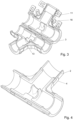
- Fig. 3 shows the half shells 2, 3 in a slightly opened state without the quick couplings 6 inserted.
- the two insulation half shells 2 on which sealing position elements 13 are arranged are clearly visible so that the half shells are precisely aligned with each other when the assembly 1 is closed and can no longer be moved relative to each other.
- the sealing position elements 13 are preferably designed as a tongue and groove connection and are arranged in the insulation half shells 2.
- Fig. 4 shows a separate insulation half-shell 2 which is not yet covered by the housing half-shell 3.
Landscapes
- Engineering & Computer Science (AREA)
- General Engineering & Computer Science (AREA)
- Mechanical Engineering (AREA)
- Connector Housings Or Holding Contact Members (AREA)
- Thermal Insulation (AREA)
- Quick-Acting Or Multi-Walled Pipe Joints (AREA)
- Cable Accessories (AREA)
Priority Applications (6)
| Application Number | Priority Date | Filing Date | Title |
|---|---|---|---|
| ES22150433T ES3010376T3 (en) | 2022-01-06 | 2022-01-06 | Insulated assembly |
| PL22150433.5T PL4209702T3 (pl) | 2022-01-06 | 2022-01-06 | Izolowany podzespół |
| HUE22150433A HUE070404T2 (hu) | 2022-01-06 | 2022-01-06 | Szigetelt modul |
| EP22150433.5A EP4209702B1 (de) | 2022-01-06 | 2022-01-06 | Isolierte baugruppe |
| AU2023200007A AU2023200007A1 (en) | 2022-01-06 | 2023-01-03 | Insulated subassembly |
| US18/093,389 US12281743B2 (en) | 2022-01-06 | 2023-01-05 | Insulated subassembly |
Applications Claiming Priority (1)
| Application Number | Priority Date | Filing Date | Title |
|---|---|---|---|
| EP22150433.5A EP4209702B1 (de) | 2022-01-06 | 2022-01-06 | Isolierte baugruppe |
Publications (3)
| Publication Number | Publication Date |
|---|---|
| EP4209702A1 EP4209702A1 (de) | 2023-07-12 |
| EP4209702C0 EP4209702C0 (de) | 2024-12-04 |
| EP4209702B1 true EP4209702B1 (de) | 2024-12-04 |
Family
ID=79269623
Family Applications (1)
| Application Number | Title | Priority Date | Filing Date |
|---|---|---|---|
| EP22150433.5A Active EP4209702B1 (de) | 2022-01-06 | 2022-01-06 | Isolierte baugruppe |
Country Status (6)
| Country | Link |
|---|---|
| US (1) | US12281743B2 (pl) |
| EP (1) | EP4209702B1 (pl) |
| AU (1) | AU2023200007A1 (pl) |
| ES (1) | ES3010376T3 (pl) |
| HU (1) | HUE070404T2 (pl) |
| PL (1) | PL4209702T3 (pl) |
Families Citing this family (1)
| Publication number | Priority date | Publication date | Assignee | Title |
|---|---|---|---|---|
| US12188600B2 (en) * | 2023-03-28 | 2025-01-07 | Advanced Drainage Systems, Inc. | Fasteners for a manifold |
Family Cites Families (23)
| Publication number | Priority date | Publication date | Assignee | Title |
|---|---|---|---|---|
| US926423A (en) * | 1906-10-09 | 1909-06-29 | Charles G Kelly | Metal-cased pipe-covering. |
| US1814134A (en) * | 1928-12-28 | 1931-07-14 | Eige Abraham | Insulation casing for pipe fittings, valves and the like |
| US2784129A (en) * | 1953-05-01 | 1957-03-05 | Gustin Bacon Mfg Co | Readily mountable pipe covering |
| US3204668A (en) * | 1961-08-28 | 1965-09-07 | Mmm Inc | Pipe insulation |
| CH448652A (de) * | 1967-05-17 | 1967-12-15 | Schibig Arthur | Schutzmantel für Rohrisolierungen |
| US3614967A (en) * | 1968-10-08 | 1971-10-26 | Royston Lab | Multilayered pipe coatings and coated pipe |
| US4478252A (en) * | 1981-02-05 | 1984-10-23 | Raychem Ltd. | Device for enclosing objects |
| FR2559874A1 (fr) * | 1984-02-16 | 1985-08-23 | Bastide Albert | Boite chauffante thermostatee autoregulante demontable |
| DE3563873D1 (en) * | 1984-11-14 | 1988-08-25 | Raychem Sa Nv | Joining insulated elongate conduit members |
| US4696324A (en) * | 1986-10-02 | 1987-09-29 | Petronko Dennis A | Heat foam insulation jacket |
| DE8703184U1 (de) * | 1986-12-24 | 1987-07-16 | Kuhlmann, Günter, 4795 Delbrück | Isolierbox für Absperr- und Regelarmaturen |
| DE3723394A1 (de) | 1987-07-15 | 1989-02-02 | Gruenzweig & Hartmann Montage | Daemmkassette und verfahren zu ihrer herstellung |
| US4830060A (en) * | 1987-11-20 | 1989-05-16 | Proto Corp. | Specialized pipefitting cover for insulated Y-shaped joint |
| FR2688860B1 (fr) * | 1992-03-20 | 1994-06-17 | Aerospatiale | Organe de drainage etanche pour circuit hydraulique. |
| US5797415A (en) * | 1993-10-15 | 1998-08-25 | Horizon Resources Corp. | Insulating jacket for hot and cold piping systems and the method of use |
| AU1951997A (en) * | 1996-01-22 | 1997-08-11 | Robert L. Mussman | Radiation shields for valves |
| US6292627B1 (en) * | 1996-03-26 | 2001-09-18 | Shell Oil Company | Electrical heating of pipelines with pipe-in-pipe and mid-line connector |
| ES2237544T3 (es) * | 2000-03-27 | 2005-08-01 | Aeroflex International Co., Ltd. | Elemento aislante para tubos. |
| US6968237B2 (en) * | 2002-05-22 | 2005-11-22 | Pacesetter, Inc. | Implantable coronary sinus lead and lead system |
| CN201789149U (zh) | 2010-08-10 | 2011-04-06 | 泰科电子(上海)有限公司 | 用于密封连接件的密封装置 |
| CN206503629U (zh) * | 2017-01-24 | 2017-09-19 | 罗伯特·博世有限公司 | 绝热保护套及选择性催化还原后处理系统的尿素溶液供应泵 |
| US20200191317A1 (en) * | 2018-12-17 | 2020-06-18 | Johns Manville | Aerogel clamshell insulation |
| US11156322B2 (en) * | 2019-10-29 | 2021-10-26 | Aeroflex Usa, Inc. | Pipe insulation jacket with reinforcement member |
-
2022
- 2022-01-06 PL PL22150433.5T patent/PL4209702T3/pl unknown
- 2022-01-06 HU HUE22150433A patent/HUE070404T2/hu unknown
- 2022-01-06 ES ES22150433T patent/ES3010376T3/es active Active
- 2022-01-06 EP EP22150433.5A patent/EP4209702B1/de active Active
-
2023
- 2023-01-03 AU AU2023200007A patent/AU2023200007A1/en active Pending
- 2023-01-05 US US18/093,389 patent/US12281743B2/en active Active
Also Published As
| Publication number | Publication date |
|---|---|
| PL4209702T3 (pl) | 2025-03-31 |
| ES3010376T3 (en) | 2025-04-02 |
| HUE070404T2 (hu) | 2025-06-28 |
| US20230213138A1 (en) | 2023-07-06 |
| EP4209702C0 (de) | 2024-12-04 |
| EP4209702A1 (de) | 2023-07-12 |
| AU2023200007A1 (en) | 2023-07-20 |
| US12281743B2 (en) | 2025-04-22 |
Similar Documents
| Publication | Publication Date | Title |
|---|---|---|
| EP4209702B1 (de) | Isolierte baugruppe | |
| EP0075901B1 (de) | Verfahren zum Verbinden von Mantelrohren zweier isolierter Leitungselemente und Verbindungsrohr zur Durchführung des Verfahrens | |
| DE202015106992U1 (de) | Modularer Fluidverteiler für ein Heiz- und/oder Kühlsystem | |
| WO2008019790A1 (de) | Abdeckungsvorrichtung | |
| EP4194735B1 (de) | Doppelrohrsystem | |
| EP2898250B1 (de) | Verbindungselement für einen beheizbaren schlauch | |
| DE102013111303A1 (de) | Elektrisches Heizelement | |
| EP2772172B1 (de) | Halteplatte und Verfahren zur Herstellung einer Halteplatte | |
| DE102008018658A1 (de) | Beheizbares Leitungselement für ein Fluid | |
| DE3723394A1 (de) | Daemmkassette und verfahren zu ihrer herstellung | |
| WO1995006809A1 (de) | Drosseleinrichtung | |
| EP3329571B1 (de) | Windschutzhülle und eine steckverbindungsvorrichtung mit einer solchen | |
| DE102007043293A1 (de) | Rohrschelle | |
| EP1610049B1 (de) | Schlauchverbindungssystem für einen beheizbaren Schlauch | |
| DE202011106817U1 (de) | Lösbare Steckverbindung | |
| EP0676580A2 (de) | Mantelteil | |
| DE20314164U1 (de) | Isoliermanschette | |
| DE2527838A1 (de) | Rohrverbindung, insbesondere fuer druckluft- oder saugfoerderleitungen | |
| DE102009021350A1 (de) | Kolbenstangenanbindung | |
| DE2102462C3 (pl) | ||
| EP4012242B1 (de) | Kunststoffrohr-t-verbindung mit mindestens einer ersten und mindestens einer weiteren kunststoffrohrleitung | |
| DE2136739A1 (de) | Kabelgarnitur mit einem aus thermoplastischem kunststoff bestehenden gehaeuse | |
| DE202008010465U1 (de) | Vorrichtung zur Isolierung eines Rohrleitungssystems | |
| DE102014209826A1 (de) | Isolierelement bzw. Isoliersystem zur Ummantelung eines Körpers | |
| DE202016003495U1 (de) | Isoliermanschette |
Legal Events
| Date | Code | Title | Description |
|---|---|---|---|
| PUAI | Public reference made under article 153(3) epc to a published international application that has entered the european phase |
Free format text: ORIGINAL CODE: 0009012 |
|
| STAA | Information on the status of an ep patent application or granted ep patent |
Free format text: STATUS: THE APPLICATION HAS BEEN PUBLISHED |
|
| AK | Designated contracting states |
Kind code of ref document: A1 Designated state(s): AL AT BE BG CH CY CZ DE DK EE ES FI FR GB GR HR HU IE IS IT LI LT LU LV MC MK MT NL NO PL PT RO RS SE SI SK SM TR |
|
| STAA | Information on the status of an ep patent application or granted ep patent |
Free format text: STATUS: REQUEST FOR EXAMINATION WAS MADE |
|
| 17P | Request for examination filed |
Effective date: 20240109 |
|
| RBV | Designated contracting states (corrected) |
Designated state(s): AL AT BE BG CH CY CZ DE DK EE ES FI FR GB GR HR HU IE IS IT LI LT LU LV MC MK MT NL NO PL PT RO RS SE SI SK SM TR |
|
| GRAP | Despatch of communication of intention to grant a patent |
Free format text: ORIGINAL CODE: EPIDOSNIGR1 |
|
| STAA | Information on the status of an ep patent application or granted ep patent |
Free format text: STATUS: GRANT OF PATENT IS INTENDED |
|
| INTG | Intention to grant announced |
Effective date: 20240704 |
|
| GRAS | Grant fee paid |
Free format text: ORIGINAL CODE: EPIDOSNIGR3 |
|
| GRAA | (expected) grant |
Free format text: ORIGINAL CODE: 0009210 |
|
| STAA | Information on the status of an ep patent application or granted ep patent |
Free format text: STATUS: THE PATENT HAS BEEN GRANTED |
|
| AK | Designated contracting states |
Kind code of ref document: B1 Designated state(s): AL AT BE BG CH CY CZ DE DK EE ES FI FR GB GR HR HU IE IS IT LI LT LU LV MC MK MT NL NO PL PT RO RS SE SI SK SM TR |
|
| REG | Reference to a national code |
Ref country code: CH Ref legal event code: EP |
|
| REG | Reference to a national code |
Ref country code: DE Ref legal event code: R096 Ref document number: 502022002260 Country of ref document: DE |
|
| REG | Reference to a national code |
Ref country code: IE Ref legal event code: FG4D Free format text: LANGUAGE OF EP DOCUMENT: GERMAN |
|
| U01 | Request for unitary effect filed |
Effective date: 20241210 |
|
| U07 | Unitary effect registered |
Designated state(s): AT BE BG DE DK EE FI FR IT LT LU LV MT NL PT RO SE SI Effective date: 20241216 |
|
| REG | Reference to a national code |
Ref country code: ES Ref legal event code: FG2A Ref document number: 3010376 Country of ref document: ES Kind code of ref document: T3 Effective date: 20250402 |
|
| U20 | Renewal fee for the european patent with unitary effect paid |
Year of fee payment: 4 Effective date: 20250221 |
|
| PG25 | Lapsed in a contracting state [announced via postgrant information from national office to epo] |
Ref country code: HR Free format text: LAPSE BECAUSE OF FAILURE TO SUBMIT A TRANSLATION OF THE DESCRIPTION OR TO PAY THE FEE WITHIN THE PRESCRIBED TIME-LIMIT Effective date: 20241204 |
|
| PG25 | Lapsed in a contracting state [announced via postgrant information from national office to epo] |
Ref country code: GR Free format text: LAPSE BECAUSE OF FAILURE TO SUBMIT A TRANSLATION OF THE DESCRIPTION OR TO PAY THE FEE WITHIN THE PRESCRIBED TIME-LIMIT Effective date: 20250305 |
|
| PGFP | Annual fee paid to national office [announced via postgrant information from national office to epo] |
Ref country code: CH Payment date: 20250201 Year of fee payment: 4 |
|
| PG25 | Lapsed in a contracting state [announced via postgrant information from national office to epo] |
Ref country code: RS Free format text: LAPSE BECAUSE OF FAILURE TO SUBMIT A TRANSLATION OF THE DESCRIPTION OR TO PAY THE FEE WITHIN THE PRESCRIBED TIME-LIMIT Effective date: 20250304 |
|
| REG | Reference to a national code |
Ref country code: HU Ref legal event code: AG4A Ref document number: E070404 Country of ref document: HU |
|
| PG25 | Lapsed in a contracting state [announced via postgrant information from national office to epo] |
Ref country code: SM Free format text: LAPSE BECAUSE OF FAILURE TO SUBMIT A TRANSLATION OF THE DESCRIPTION OR TO PAY THE FEE WITHIN THE PRESCRIBED TIME-LIMIT Effective date: 20241204 |
|
| PG25 | Lapsed in a contracting state [announced via postgrant information from national office to epo] |
Ref country code: IS Free format text: LAPSE BECAUSE OF FAILURE TO SUBMIT A TRANSLATION OF THE DESCRIPTION OR TO PAY THE FEE WITHIN THE PRESCRIBED TIME-LIMIT Effective date: 20250404 |
|
| PG25 | Lapsed in a contracting state [announced via postgrant information from national office to epo] |
Ref country code: SK Free format text: LAPSE BECAUSE OF FAILURE TO SUBMIT A TRANSLATION OF THE DESCRIPTION OR TO PAY THE FEE WITHIN THE PRESCRIBED TIME-LIMIT Effective date: 20241204 |
|
| PLBE | No opposition filed within time limit |
Free format text: ORIGINAL CODE: 0009261 |
|
| STAA | Information on the status of an ep patent application or granted ep patent |
Free format text: STATUS: NO OPPOSITION FILED WITHIN TIME LIMIT |
|
| REG | Reference to a national code |
Ref country code: CH Ref legal event code: L10 Free format text: ST27 STATUS EVENT CODE: U-0-0-L10-L00 (AS PROVIDED BY THE NATIONAL OFFICE) Effective date: 20251015 |
|
| 26N | No opposition filed |
Effective date: 20250905 |
|
| PGFP | Annual fee paid to national office [announced via postgrant information from national office to epo] |
Ref country code: CZ Payment date: 20251230 Year of fee payment: 5 |
|
| PGFP | Annual fee paid to national office [announced via postgrant information from national office to epo] |
Ref country code: PL Payment date: 20251229 Year of fee payment: 5 |
|
| REG | Reference to a national code |
Ref country code: CH Ref legal event code: U11 Free format text: ST27 STATUS EVENT CODE: U-0-0-U10-U11 (AS PROVIDED BY THE NATIONAL OFFICE) Effective date: 20260201 |
|
| PGFP | Annual fee paid to national office [announced via postgrant information from national office to epo] |
Ref country code: HU Payment date: 20260123 Year of fee payment: 5 |
|
| U20 | Renewal fee for the european patent with unitary effect paid |
Year of fee payment: 5 Effective date: 20260129 |
|
| PGFP | Annual fee paid to national office [announced via postgrant information from national office to epo] |
Ref country code: GB Payment date: 20260123 Year of fee payment: 5 |
|
| PGFP | Annual fee paid to national office [announced via postgrant information from national office to epo] |
Ref country code: MC Payment date: 20260123 Year of fee payment: 5 Ref country code: ES Payment date: 20260227 Year of fee payment: 5 |
|
| PGFP | Annual fee paid to national office [announced via postgrant information from national office to epo] |
Ref country code: NO Payment date: 20260123 Year of fee payment: 5 Ref country code: IE Payment date: 20260122 Year of fee payment: 5 |