EP4217622B1 - Zuspanneinrichtung einer scheibenbremse - Google Patents
Zuspanneinrichtung einer scheibenbremse Download PDFInfo
- Publication number
- EP4217622B1 EP4217622B1 EP21769940.4A EP21769940A EP4217622B1 EP 4217622 B1 EP4217622 B1 EP 4217622B1 EP 21769940 A EP21769940 A EP 21769940A EP 4217622 B1 EP4217622 B1 EP 4217622B1
- Authority
- EP
- European Patent Office
- Prior art keywords
- bridge
- roller
- clamping means
- brake
- disc brake
- Prior art date
- Legal status (The legal status is an assumption and is not a legal conclusion. Google has not performed a legal analysis and makes no representation as to the accuracy of the status listed.)
- Active
Links
Images


Classifications
-
- F—MECHANICAL ENGINEERING; LIGHTING; HEATING; WEAPONS; BLASTING
- F16—ENGINEERING ELEMENTS AND UNITS; GENERAL MEASURES FOR PRODUCING AND MAINTAINING EFFECTIVE FUNCTIONING OF MACHINES OR INSTALLATIONS; THERMAL INSULATION IN GENERAL
- F16D—COUPLINGS FOR TRANSMITTING ROTATION; CLUTCHES; BRAKES
- F16D55/00—Brakes with substantially-radial braking surfaces pressed together in axial direction, e.g. disc brakes
- F16D55/02—Brakes with substantially-radial braking surfaces pressed together in axial direction, e.g. disc brakes with axially-movable discs or pads pressed against axially-located rotating members
- F16D55/22—Brakes with substantially-radial braking surfaces pressed together in axial direction, e.g. disc brakes with axially-movable discs or pads pressed against axially-located rotating members by clamping an axially-located rotating disc between movable braking members, e.g. movable brake discs or brake pads
- F16D55/224—Brakes with substantially-radial braking surfaces pressed together in axial direction, e.g. disc brakes with axially-movable discs or pads pressed against axially-located rotating members by clamping an axially-located rotating disc between movable braking members, e.g. movable brake discs or brake pads with a common actuating member for the braking members
- F16D55/225—Brakes with substantially-radial braking surfaces pressed together in axial direction, e.g. disc brakes with axially-movable discs or pads pressed against axially-located rotating members by clamping an axially-located rotating disc between movable braking members, e.g. movable brake discs or brake pads with a common actuating member for the braking members the braking members being brake pads
- F16D55/2255—Brakes with substantially-radial braking surfaces pressed together in axial direction, e.g. disc brakes with axially-movable discs or pads pressed against axially-located rotating members by clamping an axially-located rotating disc between movable braking members, e.g. movable brake discs or brake pads with a common actuating member for the braking members the braking members being brake pads in which the common actuating member is pivoted
-
- F—MECHANICAL ENGINEERING; LIGHTING; HEATING; WEAPONS; BLASTING
- F16—ENGINEERING ELEMENTS AND UNITS; GENERAL MEASURES FOR PRODUCING AND MAINTAINING EFFECTIVE FUNCTIONING OF MACHINES OR INSTALLATIONS; THERMAL INSULATION IN GENERAL
- F16D—COUPLINGS FOR TRANSMITTING ROTATION; CLUTCHES; BRAKES
- F16D65/00—Parts or details
- F16D65/14—Actuating mechanisms for brakes; Means for initiating operation at a predetermined position
- F16D65/16—Actuating mechanisms for brakes; Means for initiating operation at a predetermined position arranged in or on the brake
- F16D65/18—Actuating mechanisms for brakes; Means for initiating operation at a predetermined position arranged in or on the brake adapted for drawing members together, e.g. for disc brakes
- F16D65/183—Actuating mechanisms for brakes; Means for initiating operation at a predetermined position arranged in or on the brake adapted for drawing members together, e.g. for disc brakes with force-transmitting members arranged side by side acting on a spot type force-applying member
-
- F—MECHANICAL ENGINEERING; LIGHTING; HEATING; WEAPONS; BLASTING
- F16—ENGINEERING ELEMENTS AND UNITS; GENERAL MEASURES FOR PRODUCING AND MAINTAINING EFFECTIVE FUNCTIONING OF MACHINES OR INSTALLATIONS; THERMAL INSULATION IN GENERAL
- F16D—COUPLINGS FOR TRANSMITTING ROTATION; CLUTCHES; BRAKES
- F16D65/00—Parts or details
- F16D65/38—Slack adjusters
- F16D65/40—Slack adjusters mechanical
- F16D65/52—Slack adjusters mechanical self-acting in one direction for adjusting excessive play
- F16D65/56—Slack adjusters mechanical self-acting in one direction for adjusting excessive play with screw-thread and nut
- F16D65/567—Slack adjusters mechanical self-acting in one direction for adjusting excessive play with screw-thread and nut for mounting on a disc brake
- F16D65/568—Slack adjusters mechanical self-acting in one direction for adjusting excessive play with screw-thread and nut for mounting on a disc brake for synchronous adjustment of actuators arranged in parallel
-
- F—MECHANICAL ENGINEERING; LIGHTING; HEATING; WEAPONS; BLASTING
- F16—ENGINEERING ELEMENTS AND UNITS; GENERAL MEASURES FOR PRODUCING AND MAINTAINING EFFECTIVE FUNCTIONING OF MACHINES OR INSTALLATIONS; THERMAL INSULATION IN GENERAL
- F16D—COUPLINGS FOR TRANSMITTING ROTATION; CLUTCHES; BRAKES
- F16D2121/00—Type of actuator operation force
- F16D2121/14—Mechanical
-
- F—MECHANICAL ENGINEERING; LIGHTING; HEATING; WEAPONS; BLASTING
- F16—ENGINEERING ELEMENTS AND UNITS; GENERAL MEASURES FOR PRODUCING AND MAINTAINING EFFECTIVE FUNCTIONING OF MACHINES OR INSTALLATIONS; THERMAL INSULATION IN GENERAL
- F16D—COUPLINGS FOR TRANSMITTING ROTATION; CLUTCHES; BRAKES
- F16D2125/00—Components of actuators
- F16D2125/18—Mechanical mechanisms
- F16D2125/20—Mechanical mechanisms converting rotation to linear movement or vice versa
- F16D2125/22—Mechanical mechanisms converting rotation to linear movement or vice versa acting transversely to the axis of rotation
- F16D2125/26—Cranks
-
- F—MECHANICAL ENGINEERING; LIGHTING; HEATING; WEAPONS; BLASTING
- F16—ENGINEERING ELEMENTS AND UNITS; GENERAL MEASURES FOR PRODUCING AND MAINTAINING EFFECTIVE FUNCTIONING OF MACHINES OR INSTALLATIONS; THERMAL INSULATION IN GENERAL
- F16D—COUPLINGS FOR TRANSMITTING ROTATION; CLUTCHES; BRAKES
- F16D2125/00—Components of actuators
- F16D2125/18—Mechanical mechanisms
- F16D2125/20—Mechanical mechanisms converting rotation to linear movement or vice versa
- F16D2125/22—Mechanical mechanisms converting rotation to linear movement or vice versa acting transversely to the axis of rotation
- F16D2125/28—Cams; Levers with cams
- F16D2125/32—Cams; Levers with cams acting on one cam follower
Definitions
- the invention relates to an application device of a disc brake for a commercial vehicle according to the preamble of claim 1.
- brake pads can be pressed against a vehicle-side brake disc in the event of braking.
- the application device is actuated pneumatically or electromechanically with the aid of a pivoting brake lever, which is supported on the one hand on an inner wall of a brake calliper and on the other hand on a movable bridge, for which purpose a roller bearing in the form of a roller secured axially and radially between the brake lever and the bridge is arranged.
- a bearing shell is formed in the brake lever, which is coated with a suitable plastic, resulting in a so-called DU bearing.
- a modified molded part is attached to the bridge to support the roller, which also serves to secure the roller radially and axially and, through molded-on attachments such as tabs or the like, serves as a cage return for the cages of roller bearings with which the brake lever is easily mounted on the inner wall of the brake calliper.
- Such a clamping device is known from the DE 103 07 734 B3 known.
- the EN 10 2014 108 500 A1 It is proposed to hold the roller on the bridge so that it cannot twist or slide.
- corresponding shaped areas are provided on the bridge and the roller, for example as flattened areas on the roller that rest on the support surfaces of the bridge.
- both the roller and the bridge is relatively complex, since the flattenings of the roller and the support surfaces of the bridge are designed to be flat, which is only possible with relatively complex machining.
- a clamping device in which the roller is attached to the brake lever by means of a clamp, the clamp being located in a groove in the bridge.
- the invention is based on the object of further developing a clamping device of the generic type in such a way that its service life is improved with structurally simple means and its assembly becomes easier.
- the inventive design of the application device in the form that the at least one roller is connected to the bridge by a securing element not only ensures that the roller is fixed in relation to the bridge in the axial, radial and torsional directions in the installed position of the application device, but also before installation in a brake caliper.
- the bridge and the roller can be pre-assembled as a structural unit. and used without any special assembly measures being required to install the known prior art arrangement of the roller bearing loosely relative to the bridge.
- disc brakes whose essential functional component is an application device, are manufactured as series products in large quantities This significant simplification of assembly made possible by the design according to the invention is of particular importance, especially with regard to cost minimization.
- the invention offers the advantage that the use of previously known molded parts attached to the bridge can be dispensed with, which also contributes to cost optimization.
- the at least one securing element is held in a form-fitting or friction-fitting manner on the bridge and the roller, wherein, according to a further idea of the invention, the use of a clamping sleeve proves to be particularly advantageous, which is inserted into both a bore in the bridge and a bore in the roller and is held therein in a friction-fitting manner.
- clamping sleeves are commercially available as standard parts and are therefore particularly cost-effective.
- one of the holes i.e. that of the bridge or that of the roller, can be designed as a small elongated hole.
- dowel pins can also be inserted into the appropriately prepared holes, whereby these dowel pins are also held in the bridge or the roller by friction.
- eyes can be provided on the bridge, into which two roller rollers, aligned on the same axis and arranged at a distance from each other, are pressed with their ends facing away from each other as roller roller bearings. The distance between the roller rollers to each other, so the gap created is dimensioned so that the rollers can be easily inserted.
- the eyes are conveniently molded onto the cast iron bridges. This design variant also ensures a secure hold, i.e. protection against twisting and shifting of the rollers.
- the securing element can consist of a piece of sheet metal which is pressed into a groove in the bearing point of the bridge as well as into a groove in the roller, whereby this piece of sheet metal extends in the pivoting direction of the brake lever.
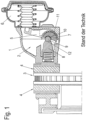
- a disc brake for a commercial vehicle according to the prior art is shown in a section.
- This disc brake has a brake disc 3 which is attached to an axle (not shown) of the commercial vehicle and is surrounded by a brake calliper 1 which can be moved in the direction of the brake disc 3.
- An application device 2 is arranged in the brake calliper 1, with which brake pads 4 can be pressed against the brake disc 3 during braking triggered by a preferably pneumatically actuated brake cylinder.
- the application device 2 acts on brake pistons (not shown) which are arranged parallel and at a distance from one another in a bridge 8 and are designed as adjusting spindles.
- a brake lever 5 of the application device 2 is operatively connected to the brake cylinder 6 and, when actuated, can be pivoted in the direction of the brake disc 3 about a roller 9 which runs parallel to the plane of the brake disc 3.
- the brake lever 5 rests on rolling elements 11, each held in a cage, which are supported on the brake lever 5, which is designed as an eccentric 7 in this area, on the one hand and on an inner wall of the brake calliper 1 on the other.
- the roller 9 as a component of a roller bearing serves as a pivot bearing for the brake lever 5 and is located in a bearing shell 10 of the eccentric 7.
- the bearing shell 10 is adapted in cross-section to the cross-sectional contour of the roller 9, as is a concave groove 12 in which the roller 9 is located.
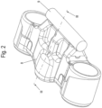
- FIGS. 2-8 represent embodiments of the application device 2 which, according to the invention, have at least one securing element connected to the bridge 8 and the roller 9.
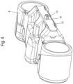
- the bridge 8 is shown as a detail of the clamping device 2.
- the securing element consists of a clamping sleeve 13, which is inserted into a bore 14 in the bridge 8 in the area of the groove 12 as well as in a bore 14 in the roller 9 and is held therein by friction.
- two rollers 9 aligned on the same axis are connected to the bridge 8 by the securing elements, whereby the two rollers 9 are arranged at a distance from one another, forming a gap.
- the securing elements are also designed as clamping sleeves 13.
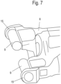
- FIG. 7 A further embodiment of the application device 2 according to the invention is shown in Figure 7 shown.
- the bridge 8 can be seen with the two rollers 9, each of which is pressed with its opposite end areas into the eyes 15 of the bridge 8 and held therein by friction. These eyes 15 are part of the bridge 8, ie they are molded into the bridge 8 during manufacture.
- Figure 8 an embodiment of the invention in which a sheet metal part 16 is provided as a securing element, which is pressed into a groove 17 of the bridge 8 on the one hand and into a groove 17 of the roller 9 on the other hand, thus establishing a frictional connection.
Landscapes
- Engineering & Computer Science (AREA)
- General Engineering & Computer Science (AREA)
- Mechanical Engineering (AREA)
- Braking Arrangements (AREA)
Description
- Die Erfindung betrifft eine Zuspanneinrichtung einer Scheibenbremse für ein Nutzfahrzeug gemäß dem Oberbegriff des Anspruchs 1.
- Mittels einer solchen Zuspanneinrichtung, die Bestandteil einer Scheibenbremse ist, sind im Fall einer Bremsung Bremsbeläge gegen eine fahrzeugseitige Bremsscheibe pressbar.
- Dabei erfolgt die Betätigung der Zuspanneinrichtung pneumatisch oder elektromechanisch unter Mitwirkung eines verschwenkbaren Bremshebels, der sich einerseits an einer Innenwand eines Bremssattels und andererseits an einer verschiebbaren Brücke abstützt, wozu eine Wälzrollenlagerung in Form einer zwischen dem Bremshebel und der Brücke axial und radial gesicherten Wälzrolle angeordnet ist.
- Zur Lagerung der Wälzrolle ist im Bremshebel eine Lagerschale ausgebildet, die mit einem geeigneten Kunststoff beschichtet ist, so dass sich eine sogenannte DU-Lagerung ergibt.
- An der Brücke wiederum ist zur Lagerung der Wälzrolle ein entsprechend modifiziertes Formteil angebracht, das überdies der radialen und axialen Sicherung der Wälzrolle dient und durch angeformte Ansätze, beispielsweise Laschen oder dergleichen, als Käfigrückführung für die Käfige von Wälzlagern dient, mit denen der Bremshebel an der Innenwand des Bremssattels leichtgängig gelagert ist. Eine solche Zuspanneinrichtung ist aus der
DE 103 07 734 B3 bekannt. - Im Fahrbetrieb hat sich jedoch gezeigt, dass die Sicherung der Wälzrolle gegen ein axiales Verschieben bislang nicht ausreicht, so dass es zum Bruch der Laschen kommen kann. Mit der möglichen Folge eines von außen nicht zu erkennenden Versagens der Bremse, was selbstredend ein nicht akzeptables Sicherheitsrisiko darstellt.
- Überdies führt die frei drehbare Lagerung der Wälzrolle vielfach zum Abtrag von Partikeln, die in das DU-Lager des Bremshebels eindringen, was insbesondere die Lebensdauer der DU-Lagerung nachteilig beeinflusst.
- Um hier Abhilfe zu schaffen, ist in der
DE 10 2014 108 500 A1 vorgeschlagen die Wälzrolle verdreh- und verschiebegesichert an der Brücke zu halten. Dazu sind an der Brücke und der Wälzrolle miteinander korrespondierende Formbereiche vorgesehen, beispielsweise als Abplattungen an der Wälzrolle, die an Stützflächen der Brücke anliegen. - Funktional hat sich diese Konstruktion bewährt. Probleme können sich jedoch beim Zusammenbau der Scheibenbremse, insbesondere der Zuspanneinrichtung ergeben, da die Wälzrolle als Einzelteil vor dem Zusammenbau als loses Teil vorliegt, was die Montage insofern erschwert, als eine Fixierung vor einer Endposition nur mit einem entsprechenden Fertigungsaufwand, d.h. einer Montagehilfe möglich ist.
- Darüber hinaus gestaltet sich auch die Ausgestaltung sowohl der Wälzrolle wie auch der Brücke relativ aufwändig, da die Abplattungen der Wälzrolle und die Stützflächen der Brücke planeben ausgebildet sind, was nur mit einer relativ aufwändigen spanenden Bearbeitung möglich ist.
- In der
DE 10 2004 042576 A1 ist eine Zuspanneinrichtung offenbart, bei der die Wälzrolle mittels einer Klammer am Bremshebel befestigt ist, wobei die Klammer in einer Nut der Brücke einliegt. Bei Betätigung des Bremshebels verdreht sich die Wälzrolle relativ zur Brücke, an der die Wälzrolle anliegt. - Der Erfindung liegt die Aufgabe zugrunde, eine Zuspanneinrichtung der gattungsgemäßen Art so weiterzuentwickeln, dass ihre Standzeit mit konstruktiv einfachen Mitteln verbessert und ihr Zusammenbau einfacher wird.
- Diese Aufgabe wird durch eine Zuspanneinrichtung mit den Merkmalen des Anspruchs 1 gelöst.
- Die erfindungsgemäße Ausgestaltung der Zuspanneinrichtung in der Form, dass die mindestens eine Wälzrolle quasi mit der Brücke durch ein Sicherungselement verbunden ist, ist nicht nur eine Fixierung der Wälzrolle, bezogen auf die Brücke, in axialer, radialer und Verdrehrichtung in eingebauter Position der Zuspanneinrichtung gewährleistet, sondern auch vor einem Einbau in einen Bremssattel. D.h., die Brücke und die Wälzrolle können als Baueinheit vormon tiert und eingesetzt werden, ohne dass besondere Montagemaßnahmen erforderlich sind, um die aus dem Stand der Technik bekannte, gegenüber der Brücke lose Anordnung der Wälzrolle zu installieren.
- Da Scheibenbremsen, deren wesentlichen Funktionskomponente jeweils eine Zuspanneinrichtung ist, als Serienprodukte in großen Stückzahlen hergestellt werden, kommt dieser durch die erfindungsgemäße Ausgestaltung mögliche deutliche Montagevereinfachung eine besondere Bedeutung zu, vor allem hinsichtlich einer Kostenminimierung.
- Darüber hinaus ergibt sich durch die Erfindung der Vorteil, dass auf den Einsatz bisher bekannter, an der Brücke befestigter Formteile verzichtet werden kann, was ebenfalls zu einer Kostenoptimierung beiträgt.
- In diesem Sinne ist auch der nunmehr mögliche Verzicht auf den Einsatz eines gehärteten Stahls zur Fertigung der Wälzrolle zu bemerken, die sich bislang aus der Reibpaarung Stahl/Stahl zwischen dem als Lagerschale ausgebildeten Formteil und der Wälzrolle ergibt.
- Das mindestens eine Sicherungselement ist form- oder reibschlüssig an der Brücke und der Wälzrolle gehalten, wobei sich, nach einem weiteren Gedanken der Erfindung, die Verwendung einer Spannhülse als besonders vorteilhaft zeigt, die sowohl in eine Bohrung der Brücke wie auch in eine Bohrung der Wälzrolle eingesteckt und darin reibschlüssig gehalten ist.
- Derartige Spannhülsen sind als Normteile im Handel erhältlich und daher besonders kostengünstig. Für einen Toleranzausgleich kann eine der Bohrungen, also die der Brücke oder die der Wälzrolle in geringem Abmaß als Langloch ausgebildet sein.
- Prinzipiell ist jedoch das Einbringen der Bohrungen ebenfalls sehr einfach und gegenüber den zum Stand der Technik beschriebenen Abflachungen der Wälzrolle einerseits und der Brücke andererseits deutlich kostengünstiger herzustellen.
- Anstelle von Spannhülsen können auch Passstifte in die entsprechend vorbereiteten Bohrungen eingesetzt werden, wobei diese Passstifte, ebenfalls reibschlüssig in der Brücke bzw. der Wälzrolle gehalten sind.
- Als eine weitere Ausführungsvariante der Sicherungselemente können Augen an der Brücke vorgesehen sein, in die als Wälzrollenlagerung zwei sich achsgleich ausgerichtete, mit Abstand zueinander angeordnete Wälzrollen mit ihren einander abgewandten Enden eingepresst sind. Der Abstand der Wälzrollen zueinander,also der gebildete Zwischenraum ist dabei so bemessen, dass die Wälzrollen problemlos einsteckbar sind.
- Die Augen sind zweckmäßigerweise an die aus Gusseisen bestehende Brücken angeformt. Auch durch diese Ausführungsvariante ist ein sicherer Halt, d.h. eine Verdreh- und Verschiebesicherung der Wälzrollen gewährleistet.
- Weiter kann des Sicherungselement aus einem Blechstück bestehen, das sowohl in eine Nut der Lagerstelle der Brücke wie auch in eine Nut der Wälzrolle eingepresst ist, wobei sich dieses Blechstück in Schwenkrichtung des Bremshebels erstreckt.
- Weitere vorteilhafte Ausbildungen der Erfindung sind in den Unteransprüchen gekennzeichnet.
- Ausführungsbeispiele der Erfindung werden nachfolgend anhand der beigefügten Zeichnungen beschrieben.
- Es zeigen:
- Fig. 1
- den schematischen Aufbau einer mit einer Zuspanneinrich-tung nach dem Stand der Technik versehenen Scheiben-bremse in einem Querschnitt
- Fig. 2
- eine Einzelheit der erfindungsgemäßen Scheibenbremse in einer perspektivischen Ansicht
- Fig. 3
- einen Schnitt durch die Einzelheit gemäß der Linie III-III in
Fig. 2 - Fig. 4
- eine Brücke der Zuspanneinrichtung in einer perspektivi-schen Ansicht
- Fig. 5
- ein weiteres Ausführungsbeispiel einer erfindungsgemäßen Zuspanneinrichtung in einer schaubildlichen Darstellung
- Fig. 6
- einen Schnitt durch die Zuspanneinrichtung nach
Fig. 5 gemäß der Linie VI-VI inFig. 5 - Fig. 7
- eine weitere Variante der erfindungsgemäßen Zuspanneinrichtung, gleichfalls in einer perspektivischen Ansicht
- Fig. 8
- eine weiteres Ausführungsbeispiel der Erfindung in einem Längsschnitt.
- In der
Fig. 1 ist eine Scheibenbremse für ein Nutzfahrzeug nach dem Stand der Technik in einem Schnitt dargestellt. Diese Scheibenbremse weist eine Bremsscheibe 3 auf, die an einer nicht gezeigten Achse des Nutzfahrzeuges befestigt ist und von einem Bremssattel 1 umfasst ist, der in Richtung der Bremsscheibe 3 verschiebbar ist. - Im Bremssattel 1 ist eine Zuspanneinrichtung 2 angeordnet, mit der bei einer über einen vorzugsweise pneumatisch betätigten Bremszylinder ausgelösten Bremsung Bremsbeläge 4 an die Bremsscheibe 3 drückbar sind.
- Die Zuspanneinrichtung 2 greift hierbei an nicht dargestellte, parallel und mit Abstand zueinander in einer Brücke 8 angeordnete, als Stellspindeln ausgebildete Bremsstempel an.
- Mit dem Bremszylinder 6 in Wirkverbindung steht ein Bremshebel 5 der Zuspanneinrichtung 2, der bei Betätigung in Richtung der Bremsscheibe 3 schwenkbar um eine Wälzrolle 9 ist, die parallel zur Ebene der Bremsscheibe 3 verläuft.
- An der der Wälzrolle 9 gegenüberliegenden Seite liegt der Bremshebel 5 an jeweils in einem Käfig gehaltenen Wälzkörpern 11 an, die sich an dem in diesem Bereich als Exzenter 7 ausgebildeten Bremshebel 5 einerseits und an einer Innenwand des Bremssattels 1 andererseits abstützen.
- Die Wälzrolle 9 als Bestandteil einer Wälzrollenlagerung dient als Drehlager für den Bremshebel 5 und liegt in einer Lagerschale 10 des Exzenters 7. Dabei ist die Lagerschale 10 im Querschnitt ebenso der Querschnittskontur der Wälzrolle 9 angepasst, wie eine konkave Rinne 12, in der die Wälzrolle 9 andererseits einliegt.
- Die
Figuren 2-8 geben Ausführungsvarianten der Zuspanneinrichtung 2 wieder, die, gemäß der Erfindung, mindestens ein mit der Brücke 8 und der Wälzrolle 9 verbundenes Sicherungselement aufweisen. - In den
Figuren 2-4 ist die Brücke 8 als Einzelheit der Zuspanneinrichtung 2 abgebildet. In diesem Beispiel besteht das Sicherungselement aus einer Spannhülse 13, die in eine Bohrung 14 sowohl der Brücke 8 im Bereich der Rinne 12 wie auch in eine Bohrung 14 der Wälzrolle 9 eingesteckt ist und darin reibschlüssig gehalten ist. - Bei der in den
Figuren 5 und6 gezeigten Variante sind zwei achsgleich ausgerichtete Wälzrollen 9 mit der Brücke 8 durch die Sicherungselemente verbunden, wobei die beiden Wälzrollen 9 abständig zueinander angeordnet sind unter Ausbildung eines Zwischenraums. Bei diesem Beispiel sind die Sicherungselemente ebenfalls als Spannhülsen 13 ausgebildet. - Eine weitere erfindungsgemäße Ausgestaltung der Zuspanneinrichtung 2 ist in der
Figur 7 abgebildet. Darin ist die Brücke 8 mit den zwei Wälzrollen 9 zu sehen, die jeweils mit ihren einander abgewandten Endbereichen in Augen 15 der Brücke 8 eingepresst und darin reibschlüssig gehalten sind. Diese Augen 15 sind Bestandteil der Brücke 8, d.h., sie sind bei der Herstellung der Brücke 8 mit angeformt. - Schließlich gibt die
Figur 8 eine Ausführung der Erfindung wieder, bei der als Sicherungselement ein Blechteil 16 vorgesehen ist, das in eine Nut 17 der Brücke 8 einerseits und in eine Nut 17 der Wälzrolle 9 eingepresst ist und so eine reibschlüssige Verbindung hergestellt ist. -
- 1
- Bremssattel
- 2
- Zuspanneinrichtung
- 3
- Bremsscheibe
- 4
- Bremsbelag
- 5
- Bremshebel
- 6
- Bremszylinder
- 7
- Exzenter
- 8
- Brücke
- 9
- Wälzrolle
- 10
- Lagerschale
- 11
- Wälzkörper
- 12
- Rinne
- 13
- Spannhülse
- 14
- Bohrung
- 15
- Auge
- 16
- Blechteil
- 17
- Nut
Claims (9)
- Zuspanneinrichtung einer Scheibenbremse für ein Nutzfahrzeug, mit einem verschwenkbaren Bremshebel (5), der sich einerseits an einer Innenwand eines Bremssattels (1) und andererseits mittelbar an einer im Bremssattel (1) verschieblich angeordneten, mindestens einen Bremsstempel tragenden Brücke (8) abstützt, wozu zwischen dem Bremshebel (5) und der Brücke (8) eine verdreh- und verschiebegesichert an der Brücke (8) anliegende Wälzrollenanordnung vorgesehen ist,
dadurch gekennzeichnet, dass die Brücke (8) und mindestens eine Wälzrolle (9) der Wälzrollenlagerung durch mindestens ein Sicherungselement verbunden sind. - Zuspanneinrichtung einer Scheibenbremse nach Anspruch 1,
dadurch gekennzeichnet, dass
das Sicherungselement form- und/oder reibschlüssig in der Brücke (8) und der Wälzrolle (9) gehalten ist. - Zuspanneinrichtung einer Scheibenbremse nach Anspruch 1 oder 2,
dadurch gekennzeichnet, dass
das Sicherungselement aus einer Spannhülse (13) oder einem Passstift besteht, die oder der in eine Bohrung (14) der Brücke (8) und der Wälzrolle (9) eingepresst ist. - Zuspanneinrichtung einer Scheibenbremse nach einem der vorhergehenden Ansprüche,
dadurch gekennzeichnet, dass
das Sicherungselement aus einem Blechteil (16) besteht, das in jeweils eine Nut (17) der Brücke (8) und der Wälzrrolle (9) eingepresst ist. - Zuspanneinrichtung einer Scheibenbremse nach einem der vorhergehenden Ansprüche,
dadurch gekennzeichnet, dass
zwei achsgleich ausgerichtete Wälzrollen (9) vorgesehen sind, die mit Abstand zueinander angeordnet sind. - Zuspanneinrichtung einer Scheibenbremse nach Anspruch 5,
dadurch gekennzeichnet, dass
jede der beiden Wälzrollen (9) in ein Auge (15) der Brücke (8) eingepresst sind. - Zuspanneinrichtung einer Scheibenbremse nach Anspruch 6,
dadurch gekennzeichnet, dass
die Augen (15) an die Brücke (8) angeformt sind. - Zuspanneinrichtung einer Scheibenbremse nach Anspruch 6 oder 7,
dadurch gekennzeichnet, dass
die Augen (15) an den sich gegenüberliegenden Enden der beiden Wälzrollen (9) positioniert sind. - Zuspanneinrichtung einer Scheibenbremse nach einem der vorhergehenden Ansprüche,
dadurch gekennzeichnet, dass
die mindestens eine Wälzrolle (9) und die Brücke (8) als Baueinheit vormontiert sind.
Applications Claiming Priority (2)
| Application Number | Priority Date | Filing Date | Title |
|---|---|---|---|
| DE102020124690.0A DE102020124690A1 (de) | 2020-09-22 | 2020-09-22 | Zuspanneinrichtung einer Scheibenbremse |
| PCT/EP2021/073618 WO2022063516A1 (de) | 2020-09-22 | 2021-08-26 | Zuspanneinrichtung einer scheibenbremse |
Publications (2)
| Publication Number | Publication Date |
|---|---|
| EP4217622A1 EP4217622A1 (de) | 2023-08-02 |
| EP4217622B1 true EP4217622B1 (de) | 2024-06-26 |
Family
ID=77750265
Family Applications (1)
| Application Number | Title | Priority Date | Filing Date |
|---|---|---|---|
| EP21769940.4A Active EP4217622B1 (de) | 2020-09-22 | 2021-08-26 | Zuspanneinrichtung einer scheibenbremse |
Country Status (9)
| Country | Link |
|---|---|
| US (1) | US20230375050A1 (de) |
| EP (1) | EP4217622B1 (de) |
| JP (1) | JP7594663B2 (de) |
| KR (1) | KR102767571B1 (de) |
| CN (1) | CN116324208A (de) |
| BR (1) | BR112023002677A2 (de) |
| CA (1) | CA3194801A1 (de) |
| DE (1) | DE102020124690A1 (de) |
| WO (1) | WO2022063516A1 (de) |
Families Citing this family (1)
| Publication number | Priority date | Publication date | Assignee | Title |
|---|---|---|---|---|
| DE102023119861A1 (de) * | 2023-07-26 | 2025-01-30 | Zf Cv Systems Europe Bv | Gleitlagerkomponente für eine Zuspannvorrichtung einer Scheibenbremse für ein Fahrzeug, insbesondere Nutzfahrzeug, Bremssattel, Scheibenbremse und Fahrzeug |
Citations (2)
| Publication number | Priority date | Publication date | Assignee | Title |
|---|---|---|---|---|
| DE10307734B3 (de) * | 2003-02-24 | 2004-09-30 | Knorr-Bremse Systeme für Nutzfahrzeuge GmbH | Scheibenbremse für ein Fahrzeug, insbesondere ein Nutzfahrzeug |
| DE102014108500A1 (de) * | 2014-06-17 | 2015-12-17 | Knorr-Bremse Systeme für Nutzfahrzeuge GmbH | Zuspanneinrichtung für eine Scheibenbremse |
Family Cites Families (16)
| Publication number | Priority date | Publication date | Assignee | Title |
|---|---|---|---|---|
| DE4308704A1 (de) * | 1993-03-18 | 1994-09-22 | Knorr Bremse Ag | Druckluftbetätigte Scheibenbremse |
| SE505339C2 (sv) | 1994-10-24 | 1997-08-11 | Haldex Ab | Skivbromstång |
| DE29522308U1 (de) * | 1994-10-24 | 2001-08-09 | Haldex Brake Products Ab, Landskrona | Scheibenbremse |
| EP0826115B1 (de) * | 1995-05-15 | 1999-12-01 | Meritor Automotive, Inc. | Zuspannvorrichtung einer scheibenbremse |
| SE516495C2 (sv) * | 2000-05-31 | 2002-01-22 | Haldex Brake Prod Ab | Bromsmekanism och bromsok för en skivbroms |
| DE10219148C1 (de) * | 2002-04-29 | 2003-09-18 | Wabco Perrot Bremsen Gmbh | Linearzuspannvorrichtung für eine Scheibenbremse |
| DE102004042576A1 (de) * | 2004-09-02 | 2006-03-30 | Knorr-Bremse Systeme für Nutzfahrzeuge GmbH | Scheibenbremse für ein Fahrzeug, insbesondere ein Nutzfahrzeug |
| DE102004058433A1 (de) * | 2004-12-03 | 2006-06-22 | Knorr-Bremse Systeme für Nutzfahrzeuge GmbH | Scheibenbremse für ein Fahrzeug |
| DE102012006101A1 (de) * | 2012-03-26 | 2013-09-26 | Knorr-Bremse Systeme für Nutzfahrzeuge GmbH | Zuspannvorrichtung für eine Scheibenbremse |
| DE102012014886A1 (de) * | 2012-07-26 | 2014-01-30 | Knorr-Bremse Systeme für Nutzfahrzeuge GmbH | Zuspanneinrichtung einer Scheibenbremse für ein Nutzfahrzeug |
| US20160230826A1 (en) | 2013-09-19 | 2016-08-11 | Tbk Co., Ltd. | Disc brake device |
| DE102014113370A1 (de) * | 2014-09-17 | 2016-03-17 | Knorr-Bremse Systeme für Nutzfahrzeuge GmbH | Scheibenbremse für ein Nutzfahrzeug |
| DE102014113848A1 (de) | 2014-09-24 | 2016-03-24 | Knorr-Bremse Systeme für Nutzfahrzeuge GmbH | Zuspanneinrichtung einer Scheibenbremse |
| DE102016103187A1 (de) | 2016-02-24 | 2017-08-24 | Knorr-Bremse Systeme für Nutzfahrzeuge GmbH | Scheibenbremse mit einer Schnellanlegevorrichtung |
| JP2019015337A (ja) | 2017-07-06 | 2019-01-31 | 曙ブレーキ工業株式会社 | ディスクブレーキ装置 |
| DE102017116112A1 (de) * | 2017-07-18 | 2019-01-24 | Bpw Bergische Achsen Kg | Scheibenbremse mit darin angeordneter Zuspannvorrichtung sowie Stützrolle für die Zuspannvorrichtung |
-
2020
- 2020-09-22 DE DE102020124690.0A patent/DE102020124690A1/de active Pending
-
2021
- 2021-08-26 BR BR112023002677A patent/BR112023002677A2/pt not_active Application Discontinuation
- 2021-08-26 CA CA3194801A patent/CA3194801A1/en active Pending
- 2021-08-26 CN CN202180064409.8A patent/CN116324208A/zh active Pending
- 2021-08-26 US US18/027,498 patent/US20230375050A1/en active Pending
- 2021-08-26 WO PCT/EP2021/073618 patent/WO2022063516A1/de not_active Ceased
- 2021-08-26 EP EP21769940.4A patent/EP4217622B1/de active Active
- 2021-08-26 KR KR1020237013325A patent/KR102767571B1/ko active Active
- 2021-08-26 JP JP2023518216A patent/JP7594663B2/ja active Active
Patent Citations (2)
| Publication number | Priority date | Publication date | Assignee | Title |
|---|---|---|---|---|
| DE10307734B3 (de) * | 2003-02-24 | 2004-09-30 | Knorr-Bremse Systeme für Nutzfahrzeuge GmbH | Scheibenbremse für ein Fahrzeug, insbesondere ein Nutzfahrzeug |
| DE102014108500A1 (de) * | 2014-06-17 | 2015-12-17 | Knorr-Bremse Systeme für Nutzfahrzeuge GmbH | Zuspanneinrichtung für eine Scheibenbremse |
Also Published As
| Publication number | Publication date |
|---|---|
| JP7594663B2 (ja) | 2024-12-04 |
| WO2022063516A1 (de) | 2022-03-31 |
| US20230375050A1 (en) | 2023-11-23 |
| KR20230067686A (ko) | 2023-05-16 |
| JP2023541703A (ja) | 2023-10-03 |
| DE102020124690A1 (de) | 2022-03-24 |
| EP4217622A1 (de) | 2023-08-02 |
| KR102767571B1 (ko) | 2025-02-12 |
| CA3194801A1 (en) | 2022-03-31 |
| CN116324208A (zh) | 2023-06-23 |
| BR112023002677A2 (pt) | 2023-04-04 |
Similar Documents
| Publication | Publication Date | Title |
|---|---|---|
| EP3359843B1 (de) | Scheibenbremse für ein nutzfahrzeug | |
| EP2217825B1 (de) | Scheibenbremse für ein nutzfahrzeug | |
| DE10307734B3 (de) | Scheibenbremse für ein Fahrzeug, insbesondere ein Nutzfahrzeug | |
| EP4065857B1 (de) | Scheibenbremse für ein nutzfahrzeug | |
| EP2831457B1 (de) | Bremsbelaganordnung für eine schiebesattel-scheibenbremse | |
| DE102015010348A1 (de) | Vorrichtung zur Befestigung eines Verschleißsensors an einem Bremshebel einer Fahrzeugbremse | |
| DE102007040143B4 (de) | Bremsscheiben/Nabenverbindung | |
| EP1809921B1 (de) | Belagträgerplatte einer scheibenbremse | |
| DE102006053183A1 (de) | Scheibenbremse, insbesondere für ein Nutzfahrzeug | |
| WO2016066561A1 (de) | Scheibenbremse für ein nutzfahrzeug | |
| DE102013011673B4 (de) | Bremsbelaghalterung einer Scheibenbremse | |
| EP2050978B1 (de) | Scheibenbremse für ein Nutzfahrzeug sowie Bremsbelag für eine Scheibenbremse | |
| DE3508039C2 (de) | Innen umgriffene Scheibenbremse, insbesondere für Kraftfahrzeuge | |
| EP4217622B1 (de) | Zuspanneinrichtung einer scheibenbremse | |
| DE2211453B2 (de) | Führung für den Sattel einer Schwimmsattel-Scheibenbremse am Bremsträger | |
| EP2385268B1 (de) | Im Bremssattel einer Scheibenbremse angeordnete Zuspanneinrichtung | |
| DE102014108500B4 (de) | Zuspanneinrichtung für eine Scheibenbremse | |
| WO2016034377A1 (de) | Scheibenbremse eines kraftfahrzeugs, bremssattel, bremsbelag und anordnung wenigstens eines bremsbelags in einer belagschachtöffnung eines bremssattels | |
| DE202013101406U1 (de) | Scheibenbremse | |
| EP2428695B1 (de) | Im Bremssattel einer Scheibenbremse angeordnete Zuspanneinrichtung | |
| WO2017036764A1 (de) | Scheibenbremse für ein nutzfahrzeug | |
| DE102004055527A1 (de) | Scheibenbremse, insbesondere für ein Nutzfahrzeug | |
| DE10346343B4 (de) | An einer Radnabe befestigbare Bremsscheibe | |
| EP3292317B1 (de) | Scheibenbremse eines nutzfahrzeugs | |
| EP4402389A1 (de) | Scheibenbremse für ein nutzfahrzeug |
Legal Events
| Date | Code | Title | Description |
|---|---|---|---|
| STAA | Information on the status of an ep patent application or granted ep patent |
Free format text: STATUS: UNKNOWN |
|
| STAA | Information on the status of an ep patent application or granted ep patent |
Free format text: STATUS: THE INTERNATIONAL PUBLICATION HAS BEEN MADE |
|
| PUAI | Public reference made under article 153(3) epc to a published international application that has entered the european phase |
Free format text: ORIGINAL CODE: 0009012 |
|
| STAA | Information on the status of an ep patent application or granted ep patent |
Free format text: STATUS: REQUEST FOR EXAMINATION WAS MADE |
|
| 17P | Request for examination filed |
Effective date: 20230424 |
|
| AK | Designated contracting states |
Kind code of ref document: A1 Designated state(s): AL AT BE BG CH CY CZ DE DK EE ES FI FR GB GR HR HU IE IS IT LI LT LU LV MC MK MT NL NO PL PT RO RS SE SI SK SM TR |
|
| DAV | Request for validation of the european patent (deleted) | ||
| DAX | Request for extension of the european patent (deleted) | ||
| GRAP | Despatch of communication of intention to grant a patent |
Free format text: ORIGINAL CODE: EPIDOSNIGR1 |
|
| STAA | Information on the status of an ep patent application or granted ep patent |
Free format text: STATUS: GRANT OF PATENT IS INTENDED |
|
| INTG | Intention to grant announced |
Effective date: 20240404 |
|
| GRAS | Grant fee paid |
Free format text: ORIGINAL CODE: EPIDOSNIGR3 |
|
| GRAA | (expected) grant |
Free format text: ORIGINAL CODE: 0009210 |
|
| STAA | Information on the status of an ep patent application or granted ep patent |
Free format text: STATUS: THE PATENT HAS BEEN GRANTED |
|
| AK | Designated contracting states |
Kind code of ref document: B1 Designated state(s): AL AT BE BG CH CY CZ DE DK EE ES FI FR GB GR HR HU IE IS IT LI LT LU LV MC MK MT NL NO PL PT RO RS SE SI SK SM TR |
|
| REG | Reference to a national code |
Ref country code: GB Ref legal event code: FG4D Free format text: NOT ENGLISH |
|
| REG | Reference to a national code |
Ref country code: CH Ref legal event code: EP |
|
| REG | Reference to a national code |
Ref country code: DE Ref legal event code: R096 Ref document number: 502021004151 Country of ref document: DE |
|
| REG | Reference to a national code |
Ref country code: SE Ref legal event code: TRGR |
|
| P01 | Opt-out of the competence of the unified patent court (upc) registered |
Free format text: CASE NUMBER: APP_38239/2024 Effective date: 20240627 |
|
| PG25 | Lapsed in a contracting state [announced via postgrant information from national office to epo] |
Ref country code: BG Free format text: LAPSE BECAUSE OF FAILURE TO SUBMIT A TRANSLATION OF THE DESCRIPTION OR TO PAY THE FEE WITHIN THE PRESCRIBED TIME-LIMIT Effective date: 20240626 |
|
| PG25 | Lapsed in a contracting state [announced via postgrant information from national office to epo] |
Ref country code: HR Free format text: LAPSE BECAUSE OF FAILURE TO SUBMIT A TRANSLATION OF THE DESCRIPTION OR TO PAY THE FEE WITHIN THE PRESCRIBED TIME-LIMIT Effective date: 20240626 Ref country code: FI Free format text: LAPSE BECAUSE OF FAILURE TO SUBMIT A TRANSLATION OF THE DESCRIPTION OR TO PAY THE FEE WITHIN THE PRESCRIBED TIME-LIMIT Effective date: 20240626 |
|
| REG | Reference to a national code |
Ref country code: LT Ref legal event code: MG9D |
|
| PG25 | Lapsed in a contracting state [announced via postgrant information from national office to epo] |
Ref country code: GR Free format text: LAPSE BECAUSE OF FAILURE TO SUBMIT A TRANSLATION OF THE DESCRIPTION OR TO PAY THE FEE WITHIN THE PRESCRIBED TIME-LIMIT Effective date: 20240927 |
|
| PG25 | Lapsed in a contracting state [announced via postgrant information from national office to epo] |
Ref country code: LV Free format text: LAPSE BECAUSE OF FAILURE TO SUBMIT A TRANSLATION OF THE DESCRIPTION OR TO PAY THE FEE WITHIN THE PRESCRIBED TIME-LIMIT Effective date: 20240626 |
|
| REG | Reference to a national code |
Ref country code: NL Ref legal event code: MP Effective date: 20240626 |
|
| PG25 | Lapsed in a contracting state [announced via postgrant information from national office to epo] |
Ref country code: NO Free format text: LAPSE BECAUSE OF FAILURE TO SUBMIT A TRANSLATION OF THE DESCRIPTION OR TO PAY THE FEE WITHIN THE PRESCRIBED TIME-LIMIT Effective date: 20240926 Ref country code: LV Free format text: LAPSE BECAUSE OF FAILURE TO SUBMIT A TRANSLATION OF THE DESCRIPTION OR TO PAY THE FEE WITHIN THE PRESCRIBED TIME-LIMIT Effective date: 20240626 Ref country code: HR Free format text: LAPSE BECAUSE OF FAILURE TO SUBMIT A TRANSLATION OF THE DESCRIPTION OR TO PAY THE FEE WITHIN THE PRESCRIBED TIME-LIMIT Effective date: 20240626 Ref country code: GR Free format text: LAPSE BECAUSE OF FAILURE TO SUBMIT A TRANSLATION OF THE DESCRIPTION OR TO PAY THE FEE WITHIN THE PRESCRIBED TIME-LIMIT Effective date: 20240927 Ref country code: FI Free format text: LAPSE BECAUSE OF FAILURE TO SUBMIT A TRANSLATION OF THE DESCRIPTION OR TO PAY THE FEE WITHIN THE PRESCRIBED TIME-LIMIT Effective date: 20240626 Ref country code: BG Free format text: LAPSE BECAUSE OF FAILURE TO SUBMIT A TRANSLATION OF THE DESCRIPTION OR TO PAY THE FEE WITHIN THE PRESCRIBED TIME-LIMIT Effective date: 20240626 Ref country code: RS Free format text: LAPSE BECAUSE OF FAILURE TO SUBMIT A TRANSLATION OF THE DESCRIPTION OR TO PAY THE FEE WITHIN THE PRESCRIBED TIME-LIMIT Effective date: 20240926 |
|
| PG25 | Lapsed in a contracting state [announced via postgrant information from national office to epo] |
Ref country code: NL Free format text: LAPSE BECAUSE OF FAILURE TO SUBMIT A TRANSLATION OF THE DESCRIPTION OR TO PAY THE FEE WITHIN THE PRESCRIBED TIME-LIMIT Effective date: 20240626 |
|
| PG25 | Lapsed in a contracting state [announced via postgrant information from national office to epo] |
Ref country code: NL Free format text: LAPSE BECAUSE OF FAILURE TO SUBMIT A TRANSLATION OF THE DESCRIPTION OR TO PAY THE FEE WITHIN THE PRESCRIBED TIME-LIMIT Effective date: 20240626 |
|
| PG25 | Lapsed in a contracting state [announced via postgrant information from national office to epo] |
Ref country code: PT Free format text: LAPSE BECAUSE OF FAILURE TO SUBMIT A TRANSLATION OF THE DESCRIPTION OR TO PAY THE FEE WITHIN THE PRESCRIBED TIME-LIMIT Effective date: 20241028 |
|
| PG25 | Lapsed in a contracting state [announced via postgrant information from national office to epo] |
Ref country code: PT Free format text: LAPSE BECAUSE OF FAILURE TO SUBMIT A TRANSLATION OF THE DESCRIPTION OR TO PAY THE FEE WITHIN THE PRESCRIBED TIME-LIMIT Effective date: 20241028 |
|
| PG25 | Lapsed in a contracting state [announced via postgrant information from national office to epo] |
Ref country code: PL Free format text: LAPSE BECAUSE OF FAILURE TO SUBMIT A TRANSLATION OF THE DESCRIPTION OR TO PAY THE FEE WITHIN THE PRESCRIBED TIME-LIMIT Effective date: 20240626 |
|
| PG25 | Lapsed in a contracting state [announced via postgrant information from national office to epo] |
Ref country code: EE Free format text: LAPSE BECAUSE OF FAILURE TO SUBMIT A TRANSLATION OF THE DESCRIPTION OR TO PAY THE FEE WITHIN THE PRESCRIBED TIME-LIMIT Effective date: 20240626 |
|
| PG25 | Lapsed in a contracting state [announced via postgrant information from national office to epo] |
Ref country code: IS Free format text: LAPSE BECAUSE OF FAILURE TO SUBMIT A TRANSLATION OF THE DESCRIPTION OR TO PAY THE FEE WITHIN THE PRESCRIBED TIME-LIMIT Effective date: 20241026 |
|
| PG25 | Lapsed in a contracting state [announced via postgrant information from national office to epo] |
Ref country code: CZ Free format text: LAPSE BECAUSE OF FAILURE TO SUBMIT A TRANSLATION OF THE DESCRIPTION OR TO PAY THE FEE WITHIN THE PRESCRIBED TIME-LIMIT Effective date: 20240626 |
|
| PG25 | Lapsed in a contracting state [announced via postgrant information from national office to epo] |
Ref country code: RO Free format text: LAPSE BECAUSE OF FAILURE TO SUBMIT A TRANSLATION OF THE DESCRIPTION OR TO PAY THE FEE WITHIN THE PRESCRIBED TIME-LIMIT Effective date: 20240626 Ref country code: SK Free format text: LAPSE BECAUSE OF FAILURE TO SUBMIT A TRANSLATION OF THE DESCRIPTION OR TO PAY THE FEE WITHIN THE PRESCRIBED TIME-LIMIT Effective date: 20240626 |
|
| PG25 | Lapsed in a contracting state [announced via postgrant information from national office to epo] |
Ref country code: ES Free format text: LAPSE BECAUSE OF FAILURE TO SUBMIT A TRANSLATION OF THE DESCRIPTION OR TO PAY THE FEE WITHIN THE PRESCRIBED TIME-LIMIT Effective date: 20240626 Ref country code: SM Free format text: LAPSE BECAUSE OF FAILURE TO SUBMIT A TRANSLATION OF THE DESCRIPTION OR TO PAY THE FEE WITHIN THE PRESCRIBED TIME-LIMIT Effective date: 20240626 |
|
| PG25 | Lapsed in a contracting state [announced via postgrant information from national office to epo] |
Ref country code: SM Free format text: LAPSE BECAUSE OF FAILURE TO SUBMIT A TRANSLATION OF THE DESCRIPTION OR TO PAY THE FEE WITHIN THE PRESCRIBED TIME-LIMIT Effective date: 20240626 Ref country code: SK Free format text: LAPSE BECAUSE OF FAILURE TO SUBMIT A TRANSLATION OF THE DESCRIPTION OR TO PAY THE FEE WITHIN THE PRESCRIBED TIME-LIMIT Effective date: 20240626 Ref country code: RO Free format text: LAPSE BECAUSE OF FAILURE TO SUBMIT A TRANSLATION OF THE DESCRIPTION OR TO PAY THE FEE WITHIN THE PRESCRIBED TIME-LIMIT Effective date: 20240626 Ref country code: PL Free format text: LAPSE BECAUSE OF FAILURE TO SUBMIT A TRANSLATION OF THE DESCRIPTION OR TO PAY THE FEE WITHIN THE PRESCRIBED TIME-LIMIT Effective date: 20240626 Ref country code: IS Free format text: LAPSE BECAUSE OF FAILURE TO SUBMIT A TRANSLATION OF THE DESCRIPTION OR TO PAY THE FEE WITHIN THE PRESCRIBED TIME-LIMIT Effective date: 20241026 Ref country code: ES Free format text: LAPSE BECAUSE OF FAILURE TO SUBMIT A TRANSLATION OF THE DESCRIPTION OR TO PAY THE FEE WITHIN THE PRESCRIBED TIME-LIMIT Effective date: 20240626 Ref country code: EE Free format text: LAPSE BECAUSE OF FAILURE TO SUBMIT A TRANSLATION OF THE DESCRIPTION OR TO PAY THE FEE WITHIN THE PRESCRIBED TIME-LIMIT Effective date: 20240626 Ref country code: CZ Free format text: LAPSE BECAUSE OF FAILURE TO SUBMIT A TRANSLATION OF THE DESCRIPTION OR TO PAY THE FEE WITHIN THE PRESCRIBED TIME-LIMIT Effective date: 20240626 |
|
| REG | Reference to a national code |
Ref country code: DE Ref legal event code: R097 Ref document number: 502021004151 Country of ref document: DE |
|
| REG | Reference to a national code |
Ref country code: CH Ref legal event code: PL |
|
| PG25 | Lapsed in a contracting state [announced via postgrant information from national office to epo] |
Ref country code: DK Free format text: LAPSE BECAUSE OF FAILURE TO SUBMIT A TRANSLATION OF THE DESCRIPTION OR TO PAY THE FEE WITHIN THE PRESCRIBED TIME-LIMIT Effective date: 20240626 |
|
| PG25 | Lapsed in a contracting state [announced via postgrant information from national office to epo] |
Ref country code: LU Free format text: LAPSE BECAUSE OF NON-PAYMENT OF DUE FEES Effective date: 20240826 |
|
| PG25 | Lapsed in a contracting state [announced via postgrant information from national office to epo] |
Ref country code: MC Free format text: LAPSE BECAUSE OF FAILURE TO SUBMIT A TRANSLATION OF THE DESCRIPTION OR TO PAY THE FEE WITHIN THE PRESCRIBED TIME-LIMIT Effective date: 20240626 Ref country code: CH Free format text: LAPSE BECAUSE OF NON-PAYMENT OF DUE FEES Effective date: 20240831 |
|
| PLBE | No opposition filed within time limit |
Free format text: ORIGINAL CODE: 0009261 |
|
| STAA | Information on the status of an ep patent application or granted ep patent |
Free format text: STATUS: NO OPPOSITION FILED WITHIN TIME LIMIT |
|
| 26N | No opposition filed |
Effective date: 20250327 |
|
| REG | Reference to a national code |
Ref country code: BE Ref legal event code: MM Effective date: 20240831 |
|
| PG25 | Lapsed in a contracting state [announced via postgrant information from national office to epo] |
Ref country code: BE Free format text: LAPSE BECAUSE OF NON-PAYMENT OF DUE FEES Effective date: 20240831 |
|
| PG25 | Lapsed in a contracting state [announced via postgrant information from national office to epo] |
Ref country code: FR Free format text: LAPSE BECAUSE OF NON-PAYMENT OF DUE FEES Effective date: 20240826 |
|
| PG25 | Lapsed in a contracting state [announced via postgrant information from national office to epo] |
Ref country code: IE Free format text: LAPSE BECAUSE OF NON-PAYMENT OF DUE FEES Effective date: 20240826 |
|
| PGFP | Annual fee paid to national office [announced via postgrant information from national office to epo] |
Ref country code: DE Payment date: 20250827 Year of fee payment: 5 |
|
| PGFP | Annual fee paid to national office [announced via postgrant information from national office to epo] |
Ref country code: IT Payment date: 20250821 Year of fee payment: 5 |
|
| PGFP | Annual fee paid to national office [announced via postgrant information from national office to epo] |
Ref country code: GB Payment date: 20250826 Year of fee payment: 5 |
|
| PGFP | Annual fee paid to national office [announced via postgrant information from national office to epo] |
Ref country code: AT Payment date: 20251020 Year of fee payment: 5 |
|
| PGFP | Annual fee paid to national office [announced via postgrant information from national office to epo] |
Ref country code: SE Payment date: 20250825 Year of fee payment: 5 |
|
| PG25 | Lapsed in a contracting state [announced via postgrant information from national office to epo] |
Ref country code: CY Free format text: LAPSE BECAUSE OF FAILURE TO SUBMIT A TRANSLATION OF THE DESCRIPTION OR TO PAY THE FEE WITHIN THE PRESCRIBED TIME-LIMIT; INVALID AB INITIO Effective date: 20210826 |
|
| PG25 | Lapsed in a contracting state [announced via postgrant information from national office to epo] |
Ref country code: HU Free format text: LAPSE BECAUSE OF FAILURE TO SUBMIT A TRANSLATION OF THE DESCRIPTION OR TO PAY THE FEE WITHIN THE PRESCRIBED TIME-LIMIT; INVALID AB INITIO Effective date: 20210826 |