EP4227169B1 - Système d'essuyage d'une surface vitrée d'une véhicule à moteur - Google Patents
Système d'essuyage d'une surface vitrée d'une véhicule à moteur Download PDFInfo
- Publication number
- EP4227169B1 EP4227169B1 EP22155910.7A EP22155910A EP4227169B1 EP 4227169 B1 EP4227169 B1 EP 4227169B1 EP 22155910 A EP22155910 A EP 22155910A EP 4227169 B1 EP4227169 B1 EP 4227169B1
- Authority
- EP
- European Patent Office
- Prior art keywords
- connecting member
- driver
- pivot
- groove
- wiping
- Prior art date
- Legal status (The legal status is an assumption and is not a legal conclusion. Google has not performed a legal analysis and makes no representation as to the accuracy of the status listed.)
- Active
Links
Images


Classifications
-
- B—PERFORMING OPERATIONS; TRANSPORTING
- B60—VEHICLES IN GENERAL
- B60S—SERVICING, CLEANING, REPAIRING, SUPPORTING, LIFTING, OR MANOEUVRING OF VEHICLES, NOT OTHERWISE PROVIDED FOR
- B60S1/00—Cleaning of vehicles
- B60S1/02—Cleaning windscreens, windows or optical devices
- B60S1/04—Wipers or the like, e.g. scrapers
- B60S1/32—Wipers or the like, e.g. scrapers characterised by constructional features of wiper blade arms or blades
- B60S1/34—Wiper arms; Mountings therefor
- B60S1/3486—Means to allow blade to follow curvature of the screen (i.e. rotation along longitudinal axis of the arm)
Definitions
- the invention relates to a wiper system configured to wipe a glass surface of a vehicle, and more particularly to a wiper system adapted for a complex vehicle glass surface, such as a panoramic glass surface of a vehicle.
- a vehicle typically includes a windscreen mounted at the front of the vehicle in front of a driver of the vehicle, who can see through the windscreen to the road and the front of the vehicle.
- the windscreen must be transparent to allow the driver to observe the front of the vehicle.
- the vehicle Because of its position at the front of the vehicle, water and dirt will tend to accumulate on the windscreen, particularly during foul weather conditions, obstructing the driver's view of the road ahead. To this end, the vehicle includes a wiper system to remove water and dirt deposits from the vehicle's glass surface.
- the wiper system traditionally consists of an arm extending between a first end attached to the vehicle and a second end to which a wiper blade is attached.
- the arm is connected to a shaft of an electric motor of the vehicle via its first end, the shaft of the electric motor driving the arm back and forth about a main extension axis of the arm to wipe the windscreen.
- Certain vehicles in particular buses and heavy-goods vehicles
- a panoramic glass surface as a windscreen, i.e. a glass surface with end portions that extend over/around the side edge of the vehicle.
- Such windscreens are considered particularly advantageous in that they provide exceptionally good visibility to the driver.
- the end portions can be difficult to wipe effectively for known wiper systems. This is because the wiper system can generally wipe a flat surface, but it is more complicated to wipe a window extending in at least two intersecting planes.
- the present invention is directed to a wiping system for a glass surface of a vehicle, the wiping system comprising at least one wiper blade for wiping the glass surface and an arm carrying the wiper blade, the arm comprising at least one driver configured to drive the wiper blade in a reciprocating manner, a rod at the end of which the wiper blade is arranged, and at least one connecting member arranged between the rod and the driver, the arm having a pivot connection between the connecting member and the driver and a rotational connection between the connecting member and the rod.
- the wiping system comprises a means for limiting the pivoting of the pivotal connection between the connecting member and the driver.
- the pivot connection enables at least the connecting member to be pivoted about a main extension axis of the arm, the connecting member pivoting the arm shaft and the wiper blade.
- the pivot limiting means may be configured to block the pivoting of the connecting member, i.e. to limit this pivoting to an angular sector in order to prevent the connecting member from pivoting the wiper blade too far.
- the pivot-limiting device thus locks the connecting member in a first position or a second position, the connecting member pivoting from one position to the other.
- the pivot-limiting device may be configured to block the pivoting of the connecting member during operation, defining the limits of the wiper blade's pivoting trajectory.
- the pivot-limiting device can be made to serve as a safety stop, preventing the wiping system from over-rotating and damaging the wiper system, windscreen, and/or vehicle body. Such over-rotation can occur when certain portions of the wiper blade are either blocked from freely moving or when they are forced beyond their ordinary range of motion.
- the pivotal connection is about an axis and the rotational connection is about a direction, the axis being secant to the direction.
- the pivot limiting means comprises a groove arranged on the driver and a pin projecting from the connecting member, the pin cooperating with the groove to block pivoting of the connecting member about the axis of the pivotal connection at a first end of the groove or a second end of the groove.
- the pivot limiting means comprises a groove arranged on the connecting member and a pin projecting from the driver, the pin cooperating with the groove to block pivoting of the connecting member about the axis of the pivotal connection at a first end of the groove or a second end of the groove.
- the pivot limiting means locks the connecting member in a first position and in at least a second position after pivoting the connecting member about the pivot linkage.
- the groove has a curved shape between the first end and the second end. Furthermore, the curvature of the groove is inscribed in a circle whose center is coincident with the axis of the pivot connection.
- the pin has a curved profile cooperating with the curved shape of the groove.
- the curvature of the pin is inscribed in a circle whose center is coincident with the axis of the pivot connection.
- the wiper system includes a linkage member configured to rotate at least the arm shaft about the pivot connection relative to the driver, the linkage member being configured to force rotation of the arm shaft about the pivot connection.
- the connecting member comprises at least one lever and at least one swivel joint arranged at one end of the lever.
- the driver and/or the rod comprises at least one protrusion at the end of which the ball joint is arranged.
- the present invention also relates to a method of wiping a glazed surface by a wiping system according to any of the preceding claims, the glazed surface comprising a first portion extending in a first plane and at least one second portion curved relative to the first plane.
- the method characterised in that the pivot limiting member locks the connecting member relative to the driver in a first position to wipe the first portion of the glass surface and locks the connecting member relative to the driver in a second position to wipe the second portion of the glass surface, the connecting member being pivoted about the pivot linkage to move from one position to the other.
- a longitudinal direction corresponds to a main direction of elongation of a duct of the arm of the wiping system, this longitudinal direction being parallel to a longitudinal axis L of an L, V, T shown in the figures.
- a transverse direction corresponds to a direction along which a protrusion of a driver of the arm mainly extends, this transverse direction being parallel to a transverse axis T of the reference frame L, V, T and this transverse axis T being perpendicular to the longitudinal axis L.
- a vertical direction corresponds to a direction parallel to a vertical axis V of the reference frame L, V, T, this vertical axis V being perpendicular to the longitudinal axis L and the transverse axis T
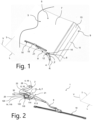
- a wiper system 1 comprises at least one arm 21 comprising a driver 2 extending between a first end 4 and a second end 6.
- the driver 2 is attached to a vehicle, and more particularly to a shaft of an electric motor that sets the wiper system 1 in motion about a rotation axis R of the wiper system 1.
- the wiping system 1 has the function of wiping a glass surface of the vehicle, which may, for example, be the windscreen 3 of the vehicle.
- the windscreen 3 is a panoramic glass surface comprising at least two parts: a first portion 5 comprising at least one flat surface 7 extending in a first plane and a second portion 9 extending in a second plane secant to the first plane.
- the second portion 9 comprises a planar surface 11 extending in the second plane and a curved surface 13 connecting the planar surface 11 of the second portion 9 to the planar surface 7 of the first portion 5.
- the wiper system 1 is driven in rotation, about the axis of rotation R. Once the electric motor is switched on, the wiper system 1 performs a back and forth movement against the windscreen 3 of the vehicle to wipe it, performing at least one pass on the first portion 5 and on the second portion 9 of the windscreen 3.
- the wiping system comprises a wiper blade 10 comprising at least one wiping strip 15 configured to be in contact with the windscreen 3 of the vehicle and to wipe it.
- the wiping strip 15 has a triangular cross-section, only one edge of which is in contact with the windscreen 3, and this edge is referred to as the wiping edge.
- the wiping strip 15 moves around a hinge, a line passing through the wiping angle of the wiping strip 15 and the hinge and forms a specific angle with the windscreen 3.
- the specific angle In order to perform an effective wipe, the specific angle must form an angle within a range of values. This angle must be maintained on the first portion 5 of the windscreen 3 as well as on its second portion 9; the invention achieves this by simple and reliable means.
- the wiping system 1 thus comprises the wiper blade 10, the arm 21 comprising on the one hand the driver 2 and on the other hand a rod 8, and a connecting member 12 which is located between the second end 6 of the driver 2 and the rod 8, the rod 8 extending between the connecting member 12 and the wiper blade 10.
- the connecting member 12 is connected to the rod 8 on the one hand and to the driver 2 on the other hand.
- the connection between the connecting member 12 and the rod 8 forms a rotational connection A around which the rod 8 and the wiper blade 10 can be rotated.
- This rotational connection A extends along a direction substantially parallel to the transverse axis T of the trihedron L, V, T.
- connection between the connecting member 12 and the driver 2 forms a pivot connection P about which the connecting member 12 and the rod 8 can be pivoted relative to the driver 2.
- This pivot connection P extends along an axis S which is substantially parallel to the longitudinal axis L of the marker L, V, T.
- the direction F of the rotational connection A and the axis S of the pivotal connection P are perpendicular to each other, when these directions are in mutually intersecting planes.
- the direction F which defines the rotational connection A extends in a plane different from the plane in which the axis S which defines the pivot connection P extends, the two planes are secant to each other.
- the wiper system 1 comprises a device for limiting the pivoting of the connecting member 12 and the driver 2 about the pivot connection P.
- This pivoting limitation device is more particularly visible in Figures 3 to 5 .
- the pivot limiting means is configured here to block the pivoting of the connecting member 12 about the pivot connection P, i.e. to limit this pivoting to a defined angular sector in order to prevent the connecting member 12 from pivoting the wiper blade 10 too far.
- the pivot limiting means thus blocks the connecting member 12 in a first position or a second position, the connecting member 12 pivoting from one position to the other.
- the driver 2 generally assumes an inclined shape and comprises a first portion 16 and a second portion 18, the first portion 16 terminating at the second end 6 and extending along the axis S that defines the pivot connection P, and the second portion 18 terminating at the first end 4 and extending along a secant direction to the axis S that defines the pivot connection P.
- the secant direction and the axis S which defines the pivot connection P form an angle between 1° and 90°, as a non-exhaustive example of the invention.
- the driver 2 generally takes the form of a "U-shaped" section according to a cross-sectional view made in a plane in which the transverse axis T and the vertical axis V lie, with two side faces 20 and a top face 22 connecting the two side faces 20, each face 20, 22 extending from the first end 4 to the second end 6 of the driver 2. At least in the first portion 16 of the driver 2, each side face 20 extends in a plane parallel to the longitudinal L and vertical V axis, while the top face 22 extends in a plane parallel to the longitudinal L and transverse T axis. The upper face 20 and side faces 20, 22 participate in delimiting a cavity 24.
- the driver 2 also comprises a front face 26, visible in figure 3 , extending in a plane parallel to the transverse axis T and vertical V, the front face 26 being located at the second end 6 of the driver 2 by joining the side faces 20 and the upper face 22.
- the driver 2 comprises a hole 28 configured to receive a shaft of the electric motor of the vehicle.
- the hole 28 extends along the vertical axis V passing through the top face 22 and within the cavity 24.
- the hole 28 takes a circular shape.
- a hole 28 taking another shape is included within the scope of the invention.
- the driver 2 has a bore 32 at the second end 6 located through the front face 26 of the driver 2.
- the bore 32 includes at least one through hole in the front face 26 connecting the cavity 24 to the exterior of the driver 2.
- the bore 32 extends along the longitudinal axis L and is configured to cooperate with the connecting member 12 to form the pivotal connection P.
- the driver 2 comprises a protrusion 30 emerging from one of the side faces 20 and extending along an axis parallel to the transverse axis T. More particularly, the protrusion 30 is located at the second end 6 and takes the form of a circular shaft. The protrusion 30 is configured to cooperate with a connecting member, an exemplary embodiment of which will be described in more detail below.
- the connecting member 12 comprises a main body 34 and at least one pivotal element 36 extending from the main body 34 to the outside of the connecting member 12 along the longitudinal axis L.
- the pivotal element 36 is a cylinder-like pin having different sections among which are an end section 38 and at least one base section 40 located between the end section 38 and the main body 34.
- the end section 38 differs from the base section 40 with a different diameter, and more particularly, the end section 38 has a smaller diameter than the diameter of the base section 40.
- the base section 40 has a constant diameter.
- the end section 38 includes a notch 42 located circularly around the pivot member 36. Furthermore, the notch 42 has a diameter smaller than the diameter of the end section 38.
- the connecting member 12 includes an axial locking device here in the form of a clip 44 configured to cooperate with the notch 42 of the pivot member 36.
- the clip 44 is a curved rod that is elastically deformable. More specifically, the clip 44 deforms its initial structure to be assembled or disassembled on the pivot member 36 in the notch 42 and returns to its initial structure after being deformed.
- the clip 44 is used to hold the connecting member 12 once the pivot member 36 is received in the bore 32 of the driver 2.
- the clip 44 has an inner diameter slightly larger than the diameter of the notch 42 to form a cooperation therewith when the clip 44 is assembled to the notch 42. Further, the outer diameter of the clip 44 is greater than the diameter of the end section 38 and the diameter of the driver bore 32.
- a starlock-type retaining ring may be used to retain the connecting member 12 in assembled position.
- Other, similar retention means may also be employed, without departing from the scope of the present invention.
- the pivot member 36 is received within the bore 32 with the end section 38 partially disposed within the cavity 24 of the driver 2.
- the diameter of the end section 38 is smaller than the diameter of the bore 32 to allow cooperation between the pivot member 36 and the bore 32.
- the clip 44 is assembled to the notch 42 once the end section 38, and more particularly the notch 42, is disposed in the cavity 24 of the driver 2.
- the pivot element 36 and the bore 32 cooperate to form the pivot connection P which rotates about the axis S.
- the pivot element 36 and the connecting member 12 can be respectively moved about this pivot connection P in the bore 32 and the driver 2.
- the channel 50 includes a crown 56 at least at the first end 52 as shown in Figure 4 , or preferably at each end 54.
- the crown 56 takes the form of a hoop projecting outwardly from the main body 34 along the transverse axis T.
- the main body 34 further includes at least one hole 58 that extends through the main body 34 from the first lateral side 54 to the second lateral side.
- the hole 58 is like a hollow cylinder, similar to the channel 50. However, the diameter of the hole 58 is smaller than the diameter of the channel 50, the hole 58 and the channel 50 being distinct and independent from each other.
- the channel 50 and the hole 58 of the connecting member 12 are configured to cooperate with the rod 8, the connecting member 12 partially connecting the rod 8 and the driver 2.
- the pivoting limitation device 61 comprises a groove 63 arranged on the driver 2 and a pin 65 projecting from the connecting member 12, the pin 65 cooperating with the groove 63 to block the pivoting of the connecting member 12 about the axis S of the pivot connection P at a first end 67 of the groove 63 or at a second end 69 of the groove 63.
- the groove 63 is arranged in the front face 26 of the driver 6, between the bore 32 and the upper face 22 along the vertical direction V.
- the pin 65 it protrudes from the main body 34 along the longitudinal direction L from the face from which the pivoting element of the connecting member 12 protrudes.
- the pivoting limitation device 61 comprises a groove 63 arranged on the connecting member 12 and a pin 65 projecting from the driver 2, the pin 65 cooperating with the groove 63 to block the pivoting of the connecting member 12 about the axis S of the pivot connection P at a first end 67 of the groove 63 or at a second end 69 of the groove 63.
- the groove 63 and the pin 65 are arranged in reverse to the arrangements described above.
- the cooperation between the groove 63 and the pin 65 are similar in this alternative of the invention.
- more than one pair of groove and pin devices may be provided between the driver and the connecting member.
- the grooves and pins should be offset about the axis S so as to avoid conflicting with each other.
- the grooves/pins may be disposed at equal angular intervals about the axis S ( e.g. four groove-pin pairs disposed at 90° intervals) to simplify construction and assembly, or alternatively disposed at unequal intervals to e.g. provide a keying effect.
- the groove 63 has a curved shape between the first end 67 and the second end 69. In other words, the groove 63 is inscribed in a circle whose center is coincident with the axis of the pivot connection.
- the pin 65 has a curved profile cooperating with the curved shape of the groove 63. Similarly, the pin 65 is inscribed in a circle whose center is coincident with the axis of the pivot connection.
- the curved shapes of the groove 63 and of the pin 65 allow the connecting member 12 to pivot about the axis S while blocking said pivoting when the pin 65 comes into abutment with either end 67, 69 of the groove 63.
- the pivoting limitation device 61 authorizes the pivoting of the connecting member 12 about the pivot linkage P through a trajectory corresponding to a predetermined angle.
- the predetermined angle may correspond to the normal angle of rotation of the wiper blade 10 as the wiper system moves from an extremity on the first portion of the windscreen 3 to an extremity on the second portion of the windscreen 3.
- the pivoting limitation device 61 effectively defines the endpoints of the rotation of the arm 21 about the axis S of the pivot connection P.
- the pivoting limitation device 61 blocks the connecting member 12 in a first position and in at least a second position after pivoting of the connecting member 12 about the pivot linkage P.
- the first position of the connecting member 12 corresponds to the position of the connecting member 12 when the pin 65 is in contact with the first end 67 of the groove 63
- the second position of the connecting member 12 corresponds to the position of the connecting member 12 when the pin 65 is in contact with the second end 69 of the groove 63.
- the pivoting limitation device 61 may authorize the pivoting of the connecting member 12 about the pivot linkage P through a trajectory corresponding to a predetermined angle which is greater than the normal angle of rotation of the wiper blade 10 over its trajectory across the windscreen 3.
- the pivoting limitation device 61 serves as a safety stop, preventing the connecting member 12 of the arm 21 from over-rotating, and consequently damaging the wiper system 1 and/or the windscreen 3.
- the wiping system includes a link member 14 configured to rotate at least the rod 8 of the arm 21 about the pivot link P relative to the driver 2, the link member 14 being configured to force the pivoting of the rod 8 of the arm 21 about the pivot link P.
- link member 14 is the element of the wiping system 1 that produces the force necessary to pivot the rod 8 and the connecting member 12 about the pivot connection P, via the kinematic relationship between the rod 8, the connecting member 12, and the driver 2 which is enforced by the link member 14.
- the link member 14 includes at least one lever 116 and at least one ball joint 118 disposed at one end of the lever 116.
- the lever 116 has a central portion 120 extending rectilinearly between a first longitudinal end 122 and a second longitudinal end 124, each longitudinal end 122, 124 comprising a ball joint 118.
- the lever 116 includes a housing at each longitudinal end 122, 124 in which the ball joint 118 is disposed.
- Each housing comprises at least one spherical portion in which the ball joint 118 can be rotated.
- each spherical portion of the lever 116 has an inner spherical side configured to accommodate the ball joint 118 and allow rotation of said ball joint 118 within the spherical portion.
- the lever 116 cooperates with the driver 2 by housing the first protrusion 30 in one of the ball joints 118.
- the rod 8 comprises a protrusion 114 extending along and parallel to the protrusion 30 of the driver 2.
- the protrusion 114 of the rod 8 thus cooperates with the other ball joint 118 of the lever 116.
- the lever 116 is held in position on the wiper system 1 by the tight guiding of each protrusion 30, 114 in its respective ball joint 118.
- the rod 8 includes at least one spring member configured to hold the wiper blade of the wiper blade against the second portion of the glass surface.
- the spring member may include hooks at each of its longitudinal ends, one of the hooks engaging a shaft partially received in the hole 58.
- the present invention also relates to a method of wiping a glass surface by a wiping system as just described. During this wiping process, when the wiping system wipes the first portion 5 of the glazed surface, the connecting member 12 and the wiper blade 10 are in the first position, the pin 65 being then in contact with the first end 67 of the groove 63.
- the link member 14 guides the connecting member 12 and the wiper blade 10 pivotally about the pivot connection so that the connecting member 12 and the wiper blade 10 move from the first position to the second position.
- the pin 65 slides in the groove 63 from the first end 67 towards the second end 69 of the groove 63 when the wiper system is in transitional motion from the first portion 5 of the glass surface to the second portion 7 of the glass surface, across the curved surface 13.
- the pivot limiting means 61 blocks the pivoting of the connecting member 12 and the wiper blade 10, the latter being in the second position.
- the link member 14 guides the connecting member 12 and the wiper blade 10 pivotally about the pivot connection so that the connecting member 12 and the wiper blade 10 move from the second position to the first position, substantially in reverse of the movement described in the preceding paragraph.
- the pin 65 slides in the groove 63 from the second end 69 towards the first end 67 of the groove 63 when the wiping system 1.
- the pivot limiting means 61 blocks the pivoting of the connecting member 12 and the wiper blade 10, the latter being in the first position.
Landscapes
- Engineering & Computer Science (AREA)
- Mechanical Engineering (AREA)
- Pivots And Pivotal Connections (AREA)
Claims (8)
- Système d'essuyage (1) pour une surface en verre (3) d'un véhicule, le système d'essuyage (1) comprenant au moins un balai d'essuie-glace (10) destiné à essuyer la surface en verre (3), et un bras (21) supportant le balai d'essuie-glace (10), le bras (21) comprenant :- au moins un dispositif d'entraînement (2), le dispositif d'entraînement (2) étant conçu pour entraîner le balai d'essuie-glace (10) en va-et-vient ;- une tige (8) à l'extrémité de laquelle est disposé le balai d'essuie-glace (10) ;- au moins un élément de raccordement (12) disposé entre la tige (8) et le dispositif d'entraînement (2)le bras (21) comportant une liaison pivotante (P) entre l'élément de raccordement (12) et le dispositif d'entraînement (2) et une liaison rotative (R) entre l'élément de raccordement (12) et la tige (8)le système d'essuyage (1) comprenant un moyen (61) pour limiter le pivotement de la liaison pivotante (P) entre l'élément de raccordement (12) et le dispositif d'entraînement (2),caractérisé en ce que le moyen de limitation de pivotement (61) comprend au moins une rainure (63) formée sur le dispositif d'entraînement (2) et au moins un ergot (65) faisant saillie à partir de l'élément de raccordement (12), et/ou au moins une rainure (63) formée sur l'élément de raccordement (12) et au moins un ergot (65) faisant saillie à partir du dispositif d'entraînement (2), ledit au moins un ergot (65) coopérant avec ladite au moins une rainure (63) pour bloquer le pivotement de l'élément de raccordement (12) autour de l'axe (S) de la liaison pivotante (P) au niveau de la liaison pivotante (P), l'ergot (65) coopérant avec la rainure (63) pour bloquer le pivotement de l'élément de raccordement (12) autour de l'axe (S) de la liaison pivotante (P) à une première extrémité (67) de l'au moins une rainure (63) ou à une seconde extrémité (69) de l'au moins une rainure (63).
- Système d'essuyage (1) selon la revendication 1, dans lequel la rainure (63) présente une forme incurvée entre la première extrémité (67) et la seconde extrémité (69).
- Système d'essuyage (1) selon l'une quelconque des revendications précédentes, la liaison pivotante (P) est réalisée autour d'un axe (S) et la liaison rotative (R) est réalisée autour d'une direction (F), l'axe (S) étant sécant à la direction (F).
- Système d'essuyage (1) selon la revendication 3, dans lequel l'ergot (65) présente un profil arqué ou circulaire coopérant avec la forme incurvée de la rainure (63).
- Système d'essuyage (1) selon l'une quelconque des revendications précédentes, comprenant un élément de liaison (14) conçu pour faire pivoter au moins la tige (8) du bras (21) autour de la liaison pivotante (P) relativement au dispositif d'entraînement (2), l'élément de liaison (14) étant conçu pour forcer le pivotement de la tige (8) du bras (21) autour de la liaison pivotante (P).
- Système d'essuyage (1) selon la revendication 5, dans lequel l'élément de liaison (14) comprend au moins un levier (116) et au moins un joint sphérique (118) disposé à une extrémité (122, 124) du levier (116).
- Système d'essuyage (1) selon la revendication 6, dans lequel le dispositif d'entraînement (2) et/ou la tige (8) comprennent au moins une saillie (30, 114) à l'extrémité de laquelle est disposé le joint sphérique (118) .
- Procédé d'essuyage d'une surface en verre (3) au moyen d'un système d'essuyage (1) selon l'une quelconque des revendications précédentes, la surface en verre (3) comprenant une première partie (5) s'étendant dans un premier plan et au moins une deuxième partie (9) courbée par rapport au premier plan, le procédé comprenant les étapes suivantes :- essuyer une première partie 5, le moyen de limitation de pivotement (61) bloquant l'élément de raccordement dans une première position ;- essuyer une surface incurvée 13 constituant une région de transition entre ladite première partie (5) et ladite deuxième partie (9), l'élément de raccordement réalisant une rotation autour d'un axe S de ladite première position vers une seconde position ;- essuyer une deuxième partie (9), le moyen de limitation de pivotement (61) bloquant l'élément de raccordement dans ladite seconde position.
Priority Applications (3)
| Application Number | Priority Date | Filing Date | Title |
|---|---|---|---|
| EP22155910.7A EP4227169B1 (fr) | 2022-02-09 | 2022-02-09 | Système d'essuyage d'une surface vitrée d'une véhicule à moteur |
| PCT/EP2023/051714 WO2023151944A1 (fr) | 2022-02-09 | 2023-01-24 | Système d'essuyage d'une surface vitrée d'un véhicule automobile |
| CN202380032636.1A CN119013170A (zh) | 2022-02-09 | 2023-01-24 | 用于机动车辆的玻璃表面的刮擦系统 |
Applications Claiming Priority (1)
| Application Number | Priority Date | Filing Date | Title |
|---|---|---|---|
| EP22155910.7A EP4227169B1 (fr) | 2022-02-09 | 2022-02-09 | Système d'essuyage d'une surface vitrée d'une véhicule à moteur |
Publications (2)
| Publication Number | Publication Date |
|---|---|
| EP4227169A1 EP4227169A1 (fr) | 2023-08-16 |
| EP4227169B1 true EP4227169B1 (fr) | 2025-04-16 |
Family
ID=80447248
Family Applications (1)
| Application Number | Title | Priority Date | Filing Date |
|---|---|---|---|
| EP22155910.7A Active EP4227169B1 (fr) | 2022-02-09 | 2022-02-09 | Système d'essuyage d'une surface vitrée d'une véhicule à moteur |
Country Status (3)
| Country | Link |
|---|---|
| EP (1) | EP4227169B1 (fr) |
| CN (1) | CN119013170A (fr) |
| WO (1) | WO2023151944A1 (fr) |
Family Cites Families (4)
| Publication number | Priority date | Publication date | Assignee | Title |
|---|---|---|---|---|
| EP0294526B1 (fr) * | 1987-06-12 | 1991-07-24 | Nippon Wiper Blade Co., Ltd. | Essuie-glace |
| FR2885100B1 (fr) * | 2005-04-29 | 2007-06-29 | Valeo Systemes Dessuyage | Essuie-glace comportant un bras support qui est de preferenc e a cinematique pantographe, ainsi qu un balai d essuyage a angle d attaque variable |
| FR2889498B1 (fr) * | 2005-08-08 | 2007-10-05 | Valeo Systemes Dessuyage | Dispositif pour l'entrainement d'un bras d'entrainement et pour l'orientation de la lame d'essuyage |
| EP3925838B1 (fr) * | 2020-06-16 | 2022-10-26 | Valeo Autosystemy SP. Z.O.O. | Système d'essuie-glace pour nettoyer une vitre de véhicule doté d'une grande courbure |
-
2022
- 2022-02-09 EP EP22155910.7A patent/EP4227169B1/fr active Active
-
2023
- 2023-01-24 CN CN202380032636.1A patent/CN119013170A/zh active Pending
- 2023-01-24 WO PCT/EP2023/051714 patent/WO2023151944A1/fr not_active Ceased
Also Published As
| Publication number | Publication date |
|---|---|
| WO2023151944A1 (fr) | 2023-08-17 |
| CN119013170A (zh) | 2024-11-22 |
| EP4227169A1 (fr) | 2023-08-16 |
Similar Documents
| Publication | Publication Date | Title |
|---|---|---|
| US7203990B2 (en) | Wiper blade | |
| KR100867563B1 (ko) | 차량의 창유리용 와이퍼 장치 | |
| US6286176B1 (en) | Windshield wiper connector | |
| JP2003506245A (ja) | 反転位置の間で運動可能な、ウィンドガラスに向かって負荷されたワイパアームを備えた、自動車のウィンドガラスのためのワイパ装置 | |
| US5182831A (en) | Windscreen wiper blade arrangement with orientation indicating means | |
| US6393654B2 (en) | Articulation system between windscreen wiper components | |
| JPH0361151A (ja) | 自動車の窓拭きワイパー用可動気流偏向器 | |
| CN108944809B (zh) | 用于将擦拭器刮片连接到擦拭系统的驱动臂的适配器 | |
| EP4227169B1 (fr) | Système d'essuyage d'une surface vitrée d'une véhicule à moteur | |
| US4641390A (en) | Windshield wiper extension mechanism | |
| KR20020029673A (ko) | 4-바아 와이퍼 아암 | |
| CN115697789B (zh) | 用于清洁高曲率车窗的雨刮器系统 | |
| EP1176069A2 (fr) | Essuie-glace en particulier pour pare-brises bombés de véhicules | |
| CN115723710A (zh) | 用于擦拭器系统的适配器 | |
| JPS63263151A (ja) | ウインドスクリーンワイパー装置 | |
| CN108622024B (zh) | 用于将风挡擦拭器刮片连接到驱动臂的装置 | |
| US11738717B2 (en) | Wiper system for cleaning a vehicle window with high curvature | |
| JP5192457B2 (ja) | ワイパアーム | |
| JP7462780B2 (ja) | ワイパーシステム接続装置用のカバー | |
| TW202241736A (zh) | 雨刷 | |
| EP3647132B1 (fr) | Essuie-glace ayant un angle d'attaque adaptable | |
| US11628808B1 (en) | Wiper arm head dual knuckle | |
| KR100783579B1 (ko) | 자동차의 싱글 와이퍼 개선 구조 | |
| GB2259851A (en) | A drive transmission device for wiper blades, in particular for the wiper blades of a vehicle windscreen | |
| JP4299198B2 (ja) | ワイパブレードおよびワイパ装置 |
Legal Events
| Date | Code | Title | Description |
|---|---|---|---|
| PUAI | Public reference made under article 153(3) epc to a published international application that has entered the european phase |
Free format text: ORIGINAL CODE: 0009012 |
|
| STAA | Information on the status of an ep patent application or granted ep patent |
Free format text: STATUS: THE APPLICATION HAS BEEN PUBLISHED |
|
| AK | Designated contracting states |
Kind code of ref document: A1 Designated state(s): AL AT BE BG CH CY CZ DE DK EE ES FI FR GB GR HR HU IE IS IT LI LT LU LV MC MK MT NL NO PL PT RO RS SE SI SK SM TR |
|
| STAA | Information on the status of an ep patent application or granted ep patent |
Free format text: STATUS: REQUEST FOR EXAMINATION WAS MADE |
|
| 17P | Request for examination filed |
Effective date: 20240315 |
|
| RBV | Designated contracting states (corrected) |
Designated state(s): AL AT BE BG CH CY CZ DE DK EE ES FI FR GB GR HR HU IE IS IT LI LT LU LV MC MK MT NL NO PL PT RO RS SE SI SK SM TR |
|
| GRAP | Despatch of communication of intention to grant a patent |
Free format text: ORIGINAL CODE: EPIDOSNIGR1 |
|
| STAA | Information on the status of an ep patent application or granted ep patent |
Free format text: STATUS: GRANT OF PATENT IS INTENDED |
|
| INTG | Intention to grant announced |
Effective date: 20241206 |
|
| GRAS | Grant fee paid |
Free format text: ORIGINAL CODE: EPIDOSNIGR3 |
|
| GRAA | (expected) grant |
Free format text: ORIGINAL CODE: 0009210 |
|
| STAA | Information on the status of an ep patent application or granted ep patent |
Free format text: STATUS: THE PATENT HAS BEEN GRANTED |
|
| AK | Designated contracting states |
Kind code of ref document: B1 Designated state(s): AL AT BE BG CH CY CZ DE DK EE ES FI FR GB GR HR HU IE IS IT LI LT LU LV MC MK MT NL NO PL PT RO RS SE SI SK SM TR |
|
| REG | Reference to a national code |
Ref country code: GB Ref legal event code: FG4D |
|
| REG | Reference to a national code |
Ref country code: CH Ref legal event code: EP |
|
| REG | Reference to a national code |
Ref country code: IE Ref legal event code: FG4D |
|
| REG | Reference to a national code |
Ref country code: DE Ref legal event code: R096 Ref document number: 602022013086 Country of ref document: DE |
|
| REG | Reference to a national code |
Ref country code: NL Ref legal event code: MP Effective date: 20250416 |
|
| PG25 | Lapsed in a contracting state [announced via postgrant information from national office to epo] |
Ref country code: NL Free format text: LAPSE BECAUSE OF FAILURE TO SUBMIT A TRANSLATION OF THE DESCRIPTION OR TO PAY THE FEE WITHIN THE PRESCRIBED TIME-LIMIT Effective date: 20250416 |
|
| REG | Reference to a national code |
Ref country code: AT Ref legal event code: MK05 Ref document number: 1785410 Country of ref document: AT Kind code of ref document: T Effective date: 20250416 |
|
| PG25 | Lapsed in a contracting state [announced via postgrant information from national office to epo] |
Ref country code: FI Free format text: LAPSE BECAUSE OF FAILURE TO SUBMIT A TRANSLATION OF THE DESCRIPTION OR TO PAY THE FEE WITHIN THE PRESCRIBED TIME-LIMIT Effective date: 20250416 Ref country code: ES Free format text: LAPSE BECAUSE OF FAILURE TO SUBMIT A TRANSLATION OF THE DESCRIPTION OR TO PAY THE FEE WITHIN THE PRESCRIBED TIME-LIMIT Effective date: 20250416 Ref country code: PT Free format text: LAPSE BECAUSE OF FAILURE TO SUBMIT A TRANSLATION OF THE DESCRIPTION OR TO PAY THE FEE WITHIN THE PRESCRIBED TIME-LIMIT Effective date: 20250818 |
|
| REG | Reference to a national code |
Ref country code: LT Ref legal event code: MG9D |
|
| PG25 | Lapsed in a contracting state [announced via postgrant information from national office to epo] |
Ref country code: GR Free format text: LAPSE BECAUSE OF FAILURE TO SUBMIT A TRANSLATION OF THE DESCRIPTION OR TO PAY THE FEE WITHIN THE PRESCRIBED TIME-LIMIT Effective date: 20250717 Ref country code: NO Free format text: LAPSE BECAUSE OF FAILURE TO SUBMIT A TRANSLATION OF THE DESCRIPTION OR TO PAY THE FEE WITHIN THE PRESCRIBED TIME-LIMIT Effective date: 20250716 |
|
| PG25 | Lapsed in a contracting state [announced via postgrant information from national office to epo] |
Ref country code: PL Free format text: LAPSE BECAUSE OF FAILURE TO SUBMIT A TRANSLATION OF THE DESCRIPTION OR TO PAY THE FEE WITHIN THE PRESCRIBED TIME-LIMIT Effective date: 20250416 |
|
| PG25 | Lapsed in a contracting state [announced via postgrant information from national office to epo] |
Ref country code: BG Free format text: LAPSE BECAUSE OF FAILURE TO SUBMIT A TRANSLATION OF THE DESCRIPTION OR TO PAY THE FEE WITHIN THE PRESCRIBED TIME-LIMIT Effective date: 20250416 |
|
| PG25 | Lapsed in a contracting state [announced via postgrant information from national office to epo] |
Ref country code: HR Free format text: LAPSE BECAUSE OF FAILURE TO SUBMIT A TRANSLATION OF THE DESCRIPTION OR TO PAY THE FEE WITHIN THE PRESCRIBED TIME-LIMIT Effective date: 20250416 |
|
| PG25 | Lapsed in a contracting state [announced via postgrant information from national office to epo] |
Ref country code: AT Free format text: LAPSE BECAUSE OF FAILURE TO SUBMIT A TRANSLATION OF THE DESCRIPTION OR TO PAY THE FEE WITHIN THE PRESCRIBED TIME-LIMIT Effective date: 20250416 |
|
| PG25 | Lapsed in a contracting state [announced via postgrant information from national office to epo] |
Ref country code: RS Free format text: LAPSE BECAUSE OF FAILURE TO SUBMIT A TRANSLATION OF THE DESCRIPTION OR TO PAY THE FEE WITHIN THE PRESCRIBED TIME-LIMIT Effective date: 20250716 |
|
| PG25 | Lapsed in a contracting state [announced via postgrant information from national office to epo] |
Ref country code: IS Free format text: LAPSE BECAUSE OF FAILURE TO SUBMIT A TRANSLATION OF THE DESCRIPTION OR TO PAY THE FEE WITHIN THE PRESCRIBED TIME-LIMIT Effective date: 20250816 |
|
| PG25 | Lapsed in a contracting state [announced via postgrant information from national office to epo] |
Ref country code: LV Free format text: LAPSE BECAUSE OF FAILURE TO SUBMIT A TRANSLATION OF THE DESCRIPTION OR TO PAY THE FEE WITHIN THE PRESCRIBED TIME-LIMIT Effective date: 20250416 |
|
| PG25 | Lapsed in a contracting state [announced via postgrant information from national office to epo] |
Ref country code: DK Free format text: LAPSE BECAUSE OF FAILURE TO SUBMIT A TRANSLATION OF THE DESCRIPTION OR TO PAY THE FEE WITHIN THE PRESCRIBED TIME-LIMIT Effective date: 20250416 Ref country code: SM Free format text: LAPSE BECAUSE OF FAILURE TO SUBMIT A TRANSLATION OF THE DESCRIPTION OR TO PAY THE FEE WITHIN THE PRESCRIBED TIME-LIMIT Effective date: 20250416 |
|
| REG | Reference to a national code |
Ref country code: DE Ref legal event code: R097 Ref document number: 602022013086 Country of ref document: DE |
|
| PG25 | Lapsed in a contracting state [announced via postgrant information from national office to epo] |
Ref country code: CZ Free format text: LAPSE BECAUSE OF FAILURE TO SUBMIT A TRANSLATION OF THE DESCRIPTION OR TO PAY THE FEE WITHIN THE PRESCRIBED TIME-LIMIT Effective date: 20250416 |
|
| PG25 | Lapsed in a contracting state [announced via postgrant information from national office to epo] |
Ref country code: EE Free format text: LAPSE BECAUSE OF FAILURE TO SUBMIT A TRANSLATION OF THE DESCRIPTION OR TO PAY THE FEE WITHIN THE PRESCRIBED TIME-LIMIT Effective date: 20250416 |
|
| PG25 | Lapsed in a contracting state [announced via postgrant information from national office to epo] |
Ref country code: SK Free format text: LAPSE BECAUSE OF FAILURE TO SUBMIT A TRANSLATION OF THE DESCRIPTION OR TO PAY THE FEE WITHIN THE PRESCRIBED TIME-LIMIT Effective date: 20250416 |
|
| PG25 | Lapsed in a contracting state [announced via postgrant information from national office to epo] |
Ref country code: IT Free format text: LAPSE BECAUSE OF FAILURE TO SUBMIT A TRANSLATION OF THE DESCRIPTION OR TO PAY THE FEE WITHIN THE PRESCRIBED TIME-LIMIT Effective date: 20250416 |
|
| PLBE | No opposition filed within time limit |
Free format text: ORIGINAL CODE: 0009261 |
|
| STAA | Information on the status of an ep patent application or granted ep patent |
Free format text: STATUS: NO OPPOSITION FILED WITHIN TIME LIMIT |
|
| REG | Reference to a national code |
Ref country code: CH Ref legal event code: L10 Free format text: ST27 STATUS EVENT CODE: U-0-0-L10-L00 (AS PROVIDED BY THE NATIONAL OFFICE) Effective date: 20260225 |
|
| 26N | No opposition filed |
Effective date: 20260119 |
|
| PGFP | Annual fee paid to national office [announced via postgrant information from national office to epo] |
Ref country code: DE Payment date: 20260206 Year of fee payment: 5 |
|
| PGFP | Annual fee paid to national office [announced via postgrant information from national office to epo] |
Ref country code: FR Payment date: 20260227 Year of fee payment: 5 |