EP4229364B1 - Modulares messgerät - Google Patents
Modulares messgerät Download PDFInfo
- Publication number
- EP4229364B1 EP4229364B1 EP21777675.6A EP21777675A EP4229364B1 EP 4229364 B1 EP4229364 B1 EP 4229364B1 EP 21777675 A EP21777675 A EP 21777675A EP 4229364 B1 EP4229364 B1 EP 4229364B1
- Authority
- EP
- European Patent Office
- Prior art keywords
- measuring tube
- shaft
- module
- measuring
- tube module
- Prior art date
- Legal status (The legal status is an assumption and is not a legal conclusion. Google has not performed a legal analysis and makes no representation as to the accuracy of the status listed.)
- Active
Links
Images


Classifications
-
- G—PHYSICS
- G01—MEASURING; TESTING
- G01F—MEASURING VOLUME, VOLUME FLOW, MASS FLOW OR LIQUID LEVEL; METERING BY VOLUME
- G01F1/00—Measuring the volume flow or mass flow of fluid or fluent solid material wherein the fluid passes through a meter in a continuous flow
- G01F1/76—Devices for measuring mass flow of a fluid or a fluent solid material
- G01F1/78—Direct mass flowmeters
- G01F1/80—Direct mass flowmeters operating by measuring pressure, force, momentum, or frequency of a fluid flow to which a rotational movement has been imparted
- G01F1/84—Coriolis or gyroscopic mass flowmeters
- G01F1/8409—Coriolis or gyroscopic mass flowmeters constructional details
- G01F1/8413—Coriolis or gyroscopic mass flowmeters constructional details means for influencing the flowmeter's motional or vibrational behaviour, e.g., conduit support or fixing means, or conduit attachments
-
- G—PHYSICS
- G01—MEASURING; TESTING
- G01F—MEASURING VOLUME, VOLUME FLOW, MASS FLOW OR LIQUID LEVEL; METERING BY VOLUME
- G01F1/00—Measuring the volume flow or mass flow of fluid or fluent solid material wherein the fluid passes through a meter in a continuous flow
- G01F1/76—Devices for measuring mass flow of a fluid or a fluent solid material
- G01F1/78—Direct mass flowmeters
- G01F1/80—Direct mass flowmeters operating by measuring pressure, force, momentum, or frequency of a fluid flow to which a rotational movement has been imparted
- G01F1/84—Coriolis or gyroscopic mass flowmeters
- G01F1/8409—Coriolis or gyroscopic mass flowmeters constructional details
- G01F1/8422—Coriolis or gyroscopic mass flowmeters constructional details exciters
-
- G—PHYSICS
- G01—MEASURING; TESTING
- G01F—MEASURING VOLUME, VOLUME FLOW, MASS FLOW OR LIQUID LEVEL; METERING BY VOLUME
- G01F1/00—Measuring the volume flow or mass flow of fluid or fluent solid material wherein the fluid passes through a meter in a continuous flow
- G01F1/76—Devices for measuring mass flow of a fluid or a fluent solid material
- G01F1/78—Direct mass flowmeters
- G01F1/80—Direct mass flowmeters operating by measuring pressure, force, momentum, or frequency of a fluid flow to which a rotational movement has been imparted
- G01F1/84—Coriolis or gyroscopic mass flowmeters
- G01F1/8409—Coriolis or gyroscopic mass flowmeters constructional details
- G01F1/8427—Coriolis or gyroscopic mass flowmeters constructional details detectors
Definitions
- the invention relates to a modular measuring device for detecting a mass flow, a viscosity, a density and/or a variable derived therefrom of a flowable medium, in particular a modular Coriolis flow meter for preferably pharmaceutical bioprocess applications.
- Coriolis flowmeters typically have one or more vibrating measuring tubes, which are set into vibration by a vibration exciter. These vibrations are transmitted along the length of the tube and are varied by the type of fluid contained in the measuring tube and its flow velocity.
- a vibration sensor or, in particular, two spaced-apart vibration sensors can record the varied vibrations at another point in the measuring tube in the form of one or more measurement signals.
- An evaluation unit can then determine the mass flow, viscosity, and/or density of the medium from the measurement signal(s).
- the vibrating measuring tubes are usually integrally connected to process connections and the housing via distributor pieces.
- Coriolis flowmeters with interchangeable disposable measuring tube assemblies with a modular design are known, in which no material connection between the measuring tube and the housing is provided, thus ensuring the exchange of the measuring tube.
- a method for producing a monolithic measuring tube arrangement of a Coriolis flowmeter with bent measuring tubes is taught, wherein the measuring tube body of the respective measuring tubes is first formed solidly from a polymer and the Channel for guiding the flowable medium is then incorporated.
- the WO 2011/099989 A1 teaches - as well as the US 10,209,113 B2 - a fixing body assembly configured to receive and support a replaceable measuring tube module comprising thin-walled plastic tubes.
- the measuring tube modules are secured in a carrier module equipped with the necessary exciters and sensors via the fixing body assembly.
- the WO 2020/035305 A1 discloses a modular Coriolis flowmeter having a body with a fluid channel connectable to process connections via retaining elements for releasable fastening.
- the mechanical properties of measuring tube modules suitable for Coriolis flowmeters can vary considerably. Therefore, specific parameters such as the calibration factor and zero point must be determined before use in a Coriolis flowmeter. It has been found that the zero point determined during the adjustment procedure usually deviates from the actual zero point of the replaceable measuring tube module in use. Such a deviation is difficult to predict. One reason for this is the extremely difficult-to-reproduce degree of attachment of the measuring tube module to the carrier module. Another influence is microfriction between the measuring tube and carrier module.
- the invention is based on the object of providing a user-friendly, modular measuring device whose zero point in use deviates only minimally from the zero point determined in the adjustment process.
- Previously known fixing devices have the disadvantage that, on the one hand, they do not adequately protect the measuring tube module against external disturbances and microfrictions and, on the other hand, the degree of fastening is not reproducible, so that in most cases, after fastening the measuring tube module in the carrier module, the actual zero point deviates from the zero point determined in the adjustment process.
- a shaft is an elongated, particularly cylindrical, rotating body used to transmit rotary motion and torque. It is typically supported by at least one pivot bearing on the support module. When torque is transmitted, the shaft is subjected to torsional stress. The eccentric part of the shaft presses against the fixing body assembly, thus clamping it in the mount.
- the mechanically detachable connection of the measuring tube module to the support module is understood to be an exchangeable connection in which no integral connections need to be removed. It is particularly user-friendly if no additional mechanical tools—such as screwdrivers—are required for the mechanically detachable connection of the measuring tube module.
- a camshaft is a rod-shaped body – equivalent to a shaft – on which at least one, particularly rounded, projection – the so-called cam – is mounted.
- the rod-shaped body rotates around its own axis, and the cam(s) mounted on it repeatedly convert this rotational movement into a short longitudinal movement.
- the fixing body assembly When the at least one measuring tube is excited, the fixing body assembly also begins to vibrate, as it is connected to the at least one measuring tube. Such movement is detrimental to measurement performance. Fixing the assembly using a camshaft suppresses these vibrations. The cam of the camshaft pushes the fixing body assembly toward the holder and clamps it in the holder. This prevents movement of the measuring tube module in the holder.
- the fixing body arrangement has a recess which is at least partially complementary to the eccentric section of the shaft, in particular to the at least one cam, wherein the recess is designed to form at least a positive connection with the eccentric section of the shaft, in particular with the at least one cam.
- a recess in the fixing body arrangement has the advantage of ensuring that the measuring tube module and/or the shaft are correctly positioned. Only when the eccentric section of the shaft or the cam can be inserted into the recess with a positive fit are the measuring tube module and the support module in a desired position relative to each other, thus preventing any zero point deviation caused by incorrect positioning and/or fixing of the measuring tube module.
- the fixing body arrangement in particular the shaft and preferably the camshaft, is mounted so as to be movable in a longitudinal direction.
- This design allows for easy operation of the locking device and user-friendly replacement of the measuring tube module, with excellent reproducibility of the force-locking and/or positive connection.
- the user moves the shaft or camshaft longitudinally, thus exposing the mount so that the measuring tube module can be inserted.
- the shaft or camshaft is moved back to the closed position and rotated to clamp the measuring tube module in the mount.
- the fixing device in particular the shaft, is designed in such a way that a movement in a longitudinal direction is at least partially carried out exclusively in a discrete number of Orientations, in particular in exactly one orientation and preferably in exactly two orientations of the fixing device, in particular of the shaft and preferably of the camshaft, are possible.
- the Fig. 1 shows a perspective view of a measuring device for pharmaceutical bioprocess applications. It is explicitly a modular Coriolis flowmeter.
- the measuring tube module 4 is suitable for being inserted into a carrier module 16 in an exchangeable and mechanically detachable manner. The mechanically detachable connection is made via a fixing device arranged on the carrier module (not shown).
- a fixing device arranged on the carrier module (not shown).
- the other components of the vibration exciter 7 and the vibration sensors 8.1, 8.2 are arranged on the carrier module 16, in particular in the receptacle 23, which is suitable for receiving the measuring tube module 4 and is formed.
- the measuring tube module 4 comprises two curved measuring tubes 3.1, 3.2 running parallel to one another, which are connected to one another via a coupler arrangement 1 consisting of four coupling elements 6.1, 6.2, and via a fixing body arrangement 5.
- the measuring tube module 4 can also comprise exclusively one measuring tube 3.1, 3.2 or more than two measuring tubes 3.1, 3.2.
- Two coupling elements 6.1 are materially bonded in an inlet and two coupling elements 6.2 are materially bonded in the outlet of the respective measuring tubes 3.1, 3.2.
- the measuring tubes 3.1, 3.2 are shaped such that the flow direction, represented by two arrows, in the inlet is oriented opposite to the flow direction in an outlet.
- a flow divider can be arranged in each of the inlet and outlet, which flow divider has a process connection for connection to a hose and/or plastic pipe system.
- exactly one flow divider body can be provided instead of two separate flow dividers, which is pushed onto the inlet and outlet and helps to decouple the measuring tube module 4 from ambient interference after installation in the carrier module 16.
- the individual coupling elements 6.1, 6.2 are plate-shaped and consist of one or two parts. The coupling elements 6.1, 6.2 can each completely or partially encompass the measuring tubes 3.1, 3.2.
- the measuring tubes 3.1, 3.2 shown are U-shaped, i.e. they each have two legs 11 that run essentially parallel to one another and are connected by a curved section.
- Exactly one magnet arrangement 9.1, 9.2 is arranged on each measuring tube 3.1, 3.2.
- a magnet 10.1 of the magnet arrangement 9.1, which forms a component of the vibration exciter 7, is arranged in the curved section.
- a magnet 10.2, which forms part of the vibration sensor 8.1, 8.2, is mounted in each of the respective legs 11.
- the magnets 10.1, 10.2 are attached to mounting surfaces.
- the mounting surfaces are located on the respective measuring tubes 3.1, 3.2.
- the measuring tube module 4 can also have one or more straight measuring tubes 3.1, 3.2, or the shape of the measuring tubes 3.1, 3.2 can differ from the shape shown.
- the measuring tube module 4 is partially inserted into a receptacle 23 of a carrier module 16.
- An arrow indicates the insertion direction.
- the insertion direction According to the embodiment, it runs perpendicular to a longitudinal direction of the receptacle 23.
- the receptacle 23 can also be designed such that the measuring tube arrangement 4 can be inserted in the longitudinal direction of the receptacle 23 (not shown).
- the carrier module 16 has a measuring and/or operating circuit 15, which is connected to the two vibration exciters 7 and a total of four vibration sensors 8.1, 8.2, in particular to the respective coil devices 25, and is designed to generate and/or detect a temporally changing magnetic field.
- the carrier module 16 has a carrier module body 22, which delimits the receptacle 23.
- the fixing body arrangement 5 of the measuring tube module 4 has mounting surfaces 26, which serve to arrange the measuring tube module 4 in a predetermined position in the carrier module 16.
- the plumb line of the mounting surface 26 points perpendicular to the longitudinal direction of the measuring tube module 4.
- the plumb line of the mounting surface 26 points in the direction of the longitudinal direction of the measuring tube module 4.
- the surface of the carrier module body 22 that is in contact with the mounting surface 26 of the fixing body arrangement 5 is referred to as the support surface 27.
- the carrier module 16 has two mutually parallel side surfaces, which delimit the receptacle 23 transversely to the longitudinal direction of the receptacle 23.
- the coil devices 25 of the vibration sensors 8.1, 8.2 and the coil device 25 of the vibration exciter 7 are arranged on or in the side surfaces.
- the coil devices 25 of the vibration sensors 8.1, 8.2 are arranged offset in the longitudinal direction of the receptacle 23 relative to the coil device 25 of the vibration exciter 7.
- the three coil devices 25 are designed as plate coils and are arranged countersunk in the side surfaces. On the side surface, three coil devices 25 are arranged substantially opposite the corresponding magnet arrangements 9.1, 9.2.
- a guide is incorporated in each of the two side surfaces, which extends perpendicular to the longitudinal direction of the receptacle 23 and parallel to the coil plane.
- the receptacle 23 extends over two end faces of the receptacle 23. This allows insertion of the measuring tube module 4 perpendicular to the longitudinal direction of the measuring tube module 4.
- the receptacle 23 extends exclusively over one end face of the carrier module 16. In this case, the measuring tube module 4 is to be inserted into the carrier module 16 in the longitudinal direction of the measuring tube module 4 - or of the carrier module 16.
- the Fig. 2 shows, in three perspective views, the fixing of a measuring tube module 4 in a receptacle of a carrier module 16 by means of an inventive embodiment of the fixing device 34.
- the measuring tube module 4 is arranged in the receptacle 23 of the carrier module.
- the fixing device 34 has a shaft 100 which is at least partially eccentric and is designed to clamp the measuring tube module 4 in the receptacle via the fixing body arrangement 35 and to mechanically releasably connect it to the carrier module 16.
- the shaft 100 of the fixing device 34 is designed as a camshaft mounted on the carrier module 16, with a cam 101.
- the shaft 100 is mounted so as to be movable in a longitudinal direction of the shaft 100 so that it does not block the receptacle when the measuring tube module 4 is inserted (see first view).
- a first projection 102 on the shaft 100 prevents the shaft 100 from falling out, thereby enabling user-friendly assembly of the measuring tube module 4.
- the first projection 102 is not intended to clamp the measuring tube module 4 in the receptacle 23.
- the fixing device 34 also comprises a first pivot bearing 104 and a second pivot bearing 105 for guiding the shaft 100 to desired degrees of freedom.
- the shaft 100 is mechanically detachable and can be connected to the first pivot bearing 104 and the second pivot bearing 105 so as to be rotatable about its own longitudinal axis.
- the cam 101 has at least one fixing surface 42, and the fixing body arrangement 35 accordingly has at least one support surface 44.
- the at least one fixing surface 42 or exactly one fixing surface 42 of the cam 101 rests on the at least one support surface 44 of the fixing body arrangement 35, which results in a force-locking and/or form-locking connection of the measuring tube module 4 with the carrier module. This connection is created by rotating the shaft 100 around its own longitudinal axis.
- the shaft 100 is also designed such that a movement thereof in a longitudinal direction is possible, at least in sections, exclusively in a discrete number of orientations of the shaft 100.
- a first section the shaft 100 can be guided through in exactly one orientation in sections
- a second section the shaft 100 can be guided through in exactly two orientations in sections.
- this is achieved in that the shaft 100, in addition to the cam 101, has the first projection 102 and a second projection 106.
- the second projection 106 like the first projection, is not designed to form the positive and/or non-positive connection.
- the first projection 102 and the second projection 106 each extend radially from the shaft 100.
- the first projection 102 and the second projection 106 are arranged offset relative to the cam 101 and to one another in the longitudinal direction of the shaft 100.
- the first projection 102 and the second projection 106 are arranged and spaced apart on the shaft 100 in such a way that, at least after the cam 101 has been guided out by the second pivot bearing 105, movement of the shaft 100 in the direction of the longitudinal axis is blocked and is preferably only possible in exactly one orientation of the shaft 100. This is achieved by means of a slot according to the embodiment.
- the shaft and the first projection 102 can be formed in two parts, i.e., the first projection 102 can be arranged as a separate component in a receptacle of the shaft 100.
- the second projection 106 essentially serves to limit the movement of the shaft 100 in its longitudinal direction and thus to bring the cam 101 into the intended target position (see second view).
- the second projection 106 can thus also be annular or at least not complementary to the opening of the bearing through which the shaft 100 is to be guided.
- the illustrated shaft 100 has a lever at one end for easier operation of the fixing device 34.
- an electronic device can be provided that causes the movement of the shaft 100 in its longitudinal direction and the rotation of the shaft 100 about the longitudinal axis, for example, by means of a linear and/or rotary motor.
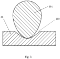
- the Fig. 3 shows a cross-section through an embodiment of the camshaft and a fixing body arrangement 35 with a recess 103, which is at least partially complementary to the at least one cam 101 or the eccentric section of the shaft.
- the recess 103 is designed to form an at least positive connection with the at least one cam 101 or the eccentric section and thus to clamp the measuring tube module in the receptacle via the fixing body arrangement 35.
- the support surface extends into the recess 103.
Landscapes
- Physics & Mathematics (AREA)
- Fluid Mechanics (AREA)
- General Physics & Mathematics (AREA)
- Measuring Volume Flow (AREA)
- Measuring Fluid Pressure (AREA)
Description
- Die Erfindung betrifft ein modulares Messgerät zum Erfassen eines Massedurchflusses, einer Viskosität, einer Dichte und/oder einer davon abgeleiteten Größe eines fließfähigen Mediums, insbesondere ein modular ausgebildetes Coriolis-Durchflussmessgerät für bevorzugt pharmazeutische Bioprozessanwendungen.
- Feldgeräte der Prozessmesstechnik mit einem Messaufnehmer des Vibrationstypen und besonders Coriolis-Durchflussmessgeräte sind seit vielen Jahren bekannt. Der grundsätzliche Aufbau eines solchen Messgerätes wird beispielsweise in der
EP 1 807 681 A1 beschrieben, wobei auf den Aufbau eines gattungsgemäßen Feldgeräts im Rahmen der vorliegenden Erfindung auf diese Druckschrift vollumfänglich Bezug genommen wird. - Typischerweise weisen Coriolis-Durchflussmessgeräte ein oder mehrere schwingfähige Messrohre auf, welche mittels eines Schwingungserregers in Schwingung versetzt werden. Diese Schwingungen übertragen sich über die Rohrlänge und werden durch die Art des im Messrohr befindlichen fließfähigen Mediums und dessen Durchflussgeschwindigkeit variiert. Ein Schwingungssensor oder insbesondere zwei voneinander beabstandete Schwingungssensoren können an einer anderen Stelle des Messrohres die variierten Schwingungen in Form eines Messsignals oder mehrerer Messsignale aufnehmen. Aus dem oder den Messsignalen kann eine Auswerteeinheit sodann den Massedurchfluss, die Viskosität und/oder die Dichte des Mediums ermitteln. Die schwingfähigen Messrohre sind üblicherweise über Verteilerstücke mit Prozessanschlüssen und Gehäuse stoffschlüssig verbunden.
- Es sind Coriolis-Durchflussmessgeräte mit austauschbaren Einweg-Messrohranordnungen mit einer modularen Bauweise bekannt, bei denen keine stoffschlüssige Verbindungen zwischen Messrohre und Gehäuse vorgesehene sind, um somit einen Austausch des Messrohres zu gewährleisten. So wird beispielsweise in der
WO 2011/099989 A1 ein Verfahren zur Herstellung einer monolithisch ausgebildeten Messrohranordnung eines Coriolis-Durchflussmessgerätes mit gebogenen Messrohren gelehrt, wobei der Messrohrkörper der jeweiligen Messrohre zuerst massiv aus einem Polymer gebildet und der Kanal zum Führen des fließfähigen Mediums anschließend spannend eingearbeitet wird. DieWO 2011/099989 A1 lehrt - ebenso wie dieUS 10,209,113 B2 - Die
WO 2020/035305 A1 offenbart ein modulares Coriolis-Durchflussmessgerät, welches einen Körper mit einem Fluidkanal aufweist, der über Halteelemente zum lösbaren Befestigen mit Prozessanschlüsse verbindbar ist. - Die mechanischen Eigenschaften der, für Coriolis-Durchflussmessgeräte geeigneten Messrohrmodule können stark variieren. Daher müssen spezifische Kenngrößen wie Kalibrationsfaktor und Nullpunkt vor dem Einsatz in einem Coriolis-Durchflussmessgerät ermittelt werden. Es hat sich herausgestellt, dass der im Justierverfahren bestimmte Nullpunkt in der Regel von dem tatsächlichen Nullpunkt des austauschbaren Messrohrmoduls im Einsatz abweicht. Eine derartige Abweichung lässt sich nur schwer vorhersagen. Ein Grund dafür ist der nur äußerst schwer zu reproduzierende Grad der Befestigung des Messrohrmoduls in dem Trägermodul. Ein weiterer Einfluss sind Mikroreibungen zwischen Messrohr- und Trägermodul.
- Der Erfindung liegt die Aufgabe zugrunde ein anwenderfreundlich zusammensetzbares, modulares Messgerät bereitzustellen, dessen Nullpunkt im Einsatz nur minimal vom im Justierverfahren ermittelten Nullpunkt abweicht.
- Die Aufgabe wird gelöst durch das modulare Messgerät nach Anspruch 1.
- Das erfindungsgemäße modulare Messgerät zum Erfassen eines Massedurchflusses, einer Viskosität, einer Dichte und/oder einer davon abgeleiteten Größe eines fließfähigen Mediums, insbesondere ein modular ausgebildetes Coriolis-Durchflussmessgerät für bevorzugt pharmazeutische Bioprozessanwendungen, umfasst:
- ein, insbesondere als Einwegartikel ausgebildetes Messrohrmodul
- wobei das Messrohrmodul mindestens ein, von einem Medium durchströmbares Messrohr umfasst,
- wobei das Messrohrmodul eine, an dem mindestens einen Messrohr befestigte Fixierkörperanordnung aufweist;
- einen Schwingungserreger welcher dazu eingerichtet ist, das Messrohr zu Schwingungen anzuregen, insbesondere umfassend einen Erregermagneten und eine Erregerspule
wobei zumindest eine Komponente des Schwingungserregers insbesondere der Erregermagnet an dem Messrohrmodul angeordnet ist; - mindestens einen Schwingungssensor, welcher dazu eingerichtet ist, die Schwingungen des mindestens einen Messrohres zu erfassen, insbesondere umfassend einen Sensormagneten und eine Sensorspule
wobei zumindest eine Komponente des Schwingungssensors insbesondere der Sensormagnet an dem Messrohrmodul angebracht ist; - ein Trägermodul insbesondere umfassend eine Aufnahme die Sensorspule und die Erregerspule
- wobei das Messrohrmodul in die Aufnahme des Trägermoduls anordenbar ist,
- wobei das Trägermodul eine Fixiervorrichtung aufweist,
- wobei die Fixiervorrichtung eine zumindest abschnittsweise exzentrisch ausgebildete Welle aufweist,
- wobei die Welle dazu eingerichtet ist, das Messrohrmodul über die Fixierkörperanordnung in der Aufnahme zu verspannen und mit dem Trägermodul mechanisch lösbar zu verbinden,
- dadurch gekennzeichnet, dass die Welle als eine am Trägermodul gelagerte Nockenwelle, mit mindestens einer Nocke ausgebildet ist.
- Bisher bekannte Fixiervorrichtungen haben den Nachteil, dass sie zum einen das Messrohrmodul nicht ausreichend gegen äußere Störungen und Mikroreibungen schützt und zum anderen der Befestigungsgrad nicht reproduzierbar ist, so dass in den meisten Fällen nach dem Befestigen des Messrohrmoduls im Trägermodul der tatsächlich vorliegende Nullpunkt von dem im Justierverfahren ermittelten Nullpunkt abweicht.
- Eine Welle ist ein länglicher, insbesondere zylinderförmiger und rotierender Körper, welcher zur Übertragung von Drehbewegungen und Drehmomenten dient. Sie wird in der Regel durch wenigstens ein Drehlager am Trägermodul unterstützt. Bei der Übertragung von Drehmomenten wird die Welle auf Torsion beansprucht. Der exzentrisch ausgebildete Teil der Welle drückt gegen die Fixierkörperanordnung und spannt diese somit in der Aufnahme ein.
- Unter der mechanisch lösbaren Verbindung des Messrohrmoduls an dem Trägermodul ist im Zusammenhang der Erfindung ein austauschbares Verbindung zu verstehen, bei dem keine stoffschlüssige Verbindungen gelöst werden müssen. Es ist besonders anwenderfreundlich, wenn für das mechanisch lösbare Verbinden des Messrohrmoduls keine zusätzlichen mechanischen Werkzeuge - wie Schraubendreher - notwendig sind.
- Eine Nockenwelle ist ein stabförmiger Körper - gleichzusetzen mit einer Welle -, auf dem mindestens ein insbesondere gerundeter Vorsprung - die sogenannte Nocke - angebracht ist. Der stabförmige Körper dreht sich um die eigene Achse, durch den oder die auf ihr angebrachten Nocken wird diese Drehbewegung wiederholt in eine kurze Längsbewegung umgewandelt.
- Beim Anregen des mindestens einen Messrohres wird auch die Fixierkörperanordnung in Schwingungen versetzt, da es mit dem mindestens einen Messrohr verbunden ist. Eine derartige Bewegung ist nachteilig für die Messperformance. Das Fixieren mittels einer Nockenwelle unterdrückt die Schwingungen. Die Nocke der Nockenwelle drückt die Fixierkörperanordnung in Richtung der Aufnahme und verspannt diese in der Aufnahmevorrichtung. Somit werden Bewegungen des Messrohrmoduls in der Aufnahme unterbunden.
- Vorteilhafte Ausgestaltung der Erfindung sind Gegenstand der Unteransprüche.
- Eine Ausgestaltung sieht vor, dass die Fixierkörperanordnung eine Vertiefung aufweist, die zumindest teilweise komplementär zum exzentrischen Abschnitt der Welle, insbesondere zur mindestens einen Nocke ausgebildet ist,
wobei die Vertiefung dazu ausgebildet ist, mit dem exzentrischen Abschnitt der Welle, insbesondere mit der mindestens einen Nocke eine zumindest formschlüssige Verbindung zu bilden. - Eine Vertiefung in der Fixierkörperanordnung hat den Vorteil, dass sichergestellt werden kann, ob eine ordnungsgemäße Anordnung des Messrohrmoduls und/oder der Welle erfolgt ist. Erst wenn sich der exzentrische Abschnitt der Welle bzw. die Nocke formschlüssig in die Vertiefung einsetzen lässt, befinden sich Messrohrmodul und Trägermodul relativ zueinander in einer Sollposition und eine durch eine fehlerhafte Anordnung und/oder Fixierung des Messrohrmoduls bedingte Abweichung des Nullpunktes kann vermieden werden.
- Eine Ausgestaltung sieht vor, dass die Fixierkörperanordnung insbesondere die Welle und bevorzugt die Nockenwelle in eine Längsrichtung beweglich gelagert ist.
- Eine derartige Ausgestaltung ermöglicht ein handliches Bedienen der Fixiervorrichtung und ein bedienerfreundliches Auswechseln des Messrohrmoduls mit einer sehr guten Reproduzierbarkeit der kraft- und/oder formschlüssigen Verbindung. Der Anwender bewegt die Welle bzw. die Nockenwelle in Längsrichtung ebendieser und legt somit die Aufnahme frei, so dass das Messrohrmodul einsetzbar ist. Zum Fixieren des Messrohrmoduls wird die Welle bzw. die Nockenwelle wieder in die Verschließposition bewegt und rotiert, um das Messrohrmodul in der Aufnahme zu verspannen.
- Eine Ausgestaltung sieht vor, dass die Fixiervorrichtung, insbesondere die Welle derart ausgebildet ist, dass eine Bewegung in eine Längsrichtung zumindest abschnittsweise ausschließlich in einer diskreten Anzahl an Orientierungen, insbesondere in genau einer Orientierung und vorzugsweise in genau zwei Orientierung der Fixiervorrichtung, insbesondere der Welle und bevorzugt der Nockenwelle möglich ist.
- Daraus ergibt sich der Vorteil, dass beim Austauschen des Messrohrmoduls ein Herausfallen der Welle bzw. der Nockenwelle aus einem der Drehlager verhindert werden kann und ein reproduzierbareres Positionieren des exzentrischen Abschnittes bzw. der mindestens einen Nocke in eine vorgesehene Sollposition realisiert wird.
- Die Erfindung wird anhand der nachfolgenden Figuren näher erläutert. Es zeigt:
-
Fig. 1 : eine perspektivische Ansicht auf eine Ausgestaltung eines modular ausgebildeten Coriolis-Durchflussmessgerätes; -
Fig. 2 : in drei perspektivischen Ansichten das Fixieren eines Messrohrmoduls in einer Aufnahme eines Trägermoduls mittels einer erfindungsgemäßen Ausgestaltung der Fixiervorrichtung; und -
Fig. 3 : einen Querschnitt durch eine Ausgestaltung der Nockenwelle und einer Fixierkörperanordnung mit einer Vertiefung. - Die
Fig. 1 zeigt eine perspektivische Darstellung eines Messgerätes für pharmazeutische Bioprozessanwendungen. Es handelt sich explizit um ein modular ausgebildetes Coriolis-Durchflussmessgerät. Das Messrohrmodul 4 ist dazu geeignet in ein Trägermodul 16 auswechselbar und mechanisch lösbar eingesetzt zu werden. Die mechanisch lösbare Verbindung erfolgt über eine am Trägermodul angeordnete Fixiervorrichtung (nicht abgebildet). Um ein einfaches Auswechseln des Messrohrmoduls 4 zu realisieren, sind nur einzelne Komponenten des Schwingungserregers 7 und der Schwingungssensoren 8.1, 8.2, in dem Fall die jeweiligen Magnetanordnungen 9.1, 9.2 an dem Messrohrmodul 4 angebracht. Diese benötigen keine elektrische Verbindung mit einer Mess- und/oder Betriebsschaltung 15. Die weiteren Komponenten des Schwingungserregers 7 und der Schwingungssensoren 8.1, 8.2 sind am Trägermodul 16, insbesondere in der Aufnahme 23 angeordnet, welche für das Aufnehmen des Messrohrmodul 4 geeignet und ausgebildet ist. Das Messrohrmodul 4 umfasst zwei gebogenen, parallel zueinander verlaufende Messrohre 3.1, 3.2, welche über eine Koppleranordnung 1, bestehend aus vier Kopplungselementen 6.1, 6.2, und über eine Fixierkörperanordnung 5 miteinander verbunden sind. Alternativ kann das Messrohrmodul 4 auch ausschließlich ein Messrohr 3.1, 3.2 oder mehr als zwei Messrohre 3.1, 3.2 umfassen. Zwei Kopplungselemente 6.1 sind in einem Einlauf und zwei Kopplungselemente 6.2 sind im Auslauf der jeweiligen Messrohre 3.1, 3.2 stoffschlüssig angebracht. Die Messrohre 3.1, 3.2 sind so geformt, dass die Strömungsrichtung, dargestellt durch zwei Pfeile, im Einlauf entgegengesetzt zur Strömungsrichtung in einem Auslauf orientiert ist. Im Einlauf und im Auslauf kann jeweils ein Strömungsteiler angeordnet, welcher einen Prozessanschluss aufweist zum Verbinden mit einem Schlauch- und/oder Kunststoffrohrsystem. Gemäß einer Ausgestaltung kann genau ein Strömungsteilerkörper statt zwei separate Strömungsteiler vorgesehen werden, welcher auf den Einlauf und Auslauf aufgeschoben wird und mit dazu beiträgt, das Messrohrmodul 4 nach dem Einbau in das Trägermodul 16 vor Störungen durch die Umgebung zu entkoppeln. Die einzelnen Kopplungselemente 6.1, 6.2 sind plattenförmig ausgebildet und sind ein- oder zweiteilig. Die Kopplungselemente 6.1, 6.2 können die Messrohre 3.1, 3.2 jeweils vollständig oder nur teilweise umgreifen. Die abgebildeten Messrohre 3.1, 3.2 sind U-förmig ausgebildet, d.h. sie weisen jeweils zwei im Wesentlichen parallel zueinander verlaufende Schenkel 11 auf, die über einen gebogenen Teilabschnitt verbunden sind. An jedem Messrohre 3.1, 3.2 ist jeweils genau eine Magnetanordnung 9.1, 9.2 angeordnet. Im gebogenen Teilabschnitt ist ein Magnet 10.1 der Magnetanordnung 9.1 angeordnet, welcher eine Komponente des Schwingungserregers 7 bildet. In den jeweiligen Schenkeln 11 ist jeweils ein Magnet 10.2 angebracht, welcher ein Teil des Schwingungssensors 8.1, 8.2 bildet. Die Magnete 10.1, 10.2 sind an Anbringflächen angebracht. Die Anbringflächen befinden sich in der Ausgestaltung an den jeweiligen Messrohren 3.1, 3.2. Alternativ kann das Messrohrmodul 4 auch ein oder mehr gerade Messrohre 3.1, 3.2 aufweisen bzw. kann die Form der Messrohre 3.1, 3.2 von der abgebildeten Form abweichen. - Das Messrohrmodul 4 ist teilweise in eine Aufnahme 23 eines Trägermoduls 16 eingeführt. Ein Pfeil deutet die Einführrichtung an. Die Einführrichtung verläuft gemäß der Ausgestaltung senkrecht zu einer Längsrichtung der Aufnahme 23. Die Aufnahme 23 kann auch derart ausgebildet sein, dass die Messrohranordnung 4 in Längsrichtung der Aufnahme 23 einzuführen ist (nicht abgebildet). Das Trägermodul 16 weist eine Mess- und/oder Betriebsschaltung 15 auf, welche mit den zwei Schwingungserregern 7 und insgesamt vier Schwingungssensoren 8.1, 8.2, insbesondere mit den jeweiligen Spulenvorrichtungen 25 verbunden und dazu eingerichtet sind ein zeitlich wechselndes Magnetfeld zu erzeugen und/oder zu erfassen. Das Trägermodul 16 weist einen Trägermodulkörper 22 auf, welcher die Aufnahme 23 begrenzt. Die Fixierkörperanordnung 5 des Messrohrmoduls 4 weist Montageflächen 26 auf, welche dazu dienen die Messrohrmodul 4 in eine vorgegebene Position in dem Trägermodul 16 anzuordnen. Gemäß der abgebildeten Ausgestaltung zeigt das Lot der Montagefläche 26 senkrecht zur Längsrichtung des Messrohrmoduls 4. Gemäß einer weiteren vorteilhaften Ausgestaltung zeigt das Lot der Montagefläche 26 in Richtung der Längsrichtung des Messrohrmoduls 4. Die mit der Montagefläche 26 der Fixierkörperanordnung 5 in Kontakt stehende Fläche des Trägermodulkörpers 22 ist als Auflagefläche 27 bezeichnet.
- Das Trägermodul 16 weist zwei parallel zueinander orientierte Seitenflächen auf, welche die Aufnahme 23 quer zur Längsrichtung der Aufnahme 23 begrenzen. An bzw. in den Seitenflächen sind die Spulenvorrichtungen 25 der Schwingungssensoren 8.1, 8.2 und die Spulenvorrichtung 25 des Schwingungserregers 7 angeordnet. Die Spulenvorrichtungen 25 der Schwingungssensoren 8.1, 8.2 sind in Längsrichtung der Aufnahme 23 zur Spulenvorrichtung 25 des Schwingungserregers 7 versetzt angeordnet. Des Weiteren sind die drei Spulenvorrichtungen 25 als Plattenspule ausgebildet und in den Seitenflächen versenkt angeordnet. An der Seitenfläche sind drei Spulenvorrichtungen 25 im Wesentlich gegenüber von den entsprechenden Magnetanordnungen 9.1, 9.2 angeordnet. In den beiden Seitenflächen ist jeweils eine Führung eingearbeitet, welche sich senkrecht zur Längsrichtung der Aufnahme 23 und parallel zur Spulenebene erstreckt. Gemäß der abgebildeten Ausgestaltung erstreckt sich die Aufnahme 23 über zwei Stirnseiten der Aufnahme 23. Dies ermöglicht ein Einführen des Messrohrmoduls 4 senkrecht zur Längsrichtung des Messrohrmodul 4. Gemäß einer weiteren Ausgestaltung erstreckt sich die Aufnahme 23 ausschließlich über eine Stirnseite des Trägermoduls 16. In dem Fall ist das Messrohrmodul 4 in Längsrichtung des Messrohrmoduls 4 - oder des Trägermodul 16 - in das Trägermodul 16 einzuführen.
- Die
Fig. 2 zeigt in drei perspektivischen Ansichten das Fixieren eines Messrohrmoduls 4 in einer Aufnahme eines Trägermoduls 16 mittels einer erfindungsgemäßen Ausgestaltung der Fixiervorrichtung 34. Das Messrohrmodul 4 ist in der Aufnahme 23 des Trägermoduls angeordnet. Die Fixiervorrichtung 34 weist eine zumindest abschnittsweise exzentrisch ausgebildete Welle 100 auf, welche dazu eingerichtet ist, das Messrohrmodul 4 über die Fixierkörperanordnung 35 in der Aufnahme zu verspannen und mit dem Trägermodul 16 mechanisch lösbar zu verbinden. In dem abgebildeten Fall ist die Welle 100 der Fixiervorrichtung 34 als eine am Trägermodul 16 gelagerte Nockenwelle, mit einer Nocke 101 ausgebildet. Um die Befestigung des Messrohrmoduls 4 in der Aufnahme 23 anwendungsbedingt anzupassen, können auch mehr als die eine dargestellte Nocke 101 vorgesehen werden. Die Welle 100 ist in eine Längsrichtung der Welle 100 beweglich gelagert, so dass diese die Aufnahme beim Einführen des Messrohrmoduls 4 nicht versperrt (siehe erste Ansicht). Ein erster Vorsprung 102 an der Welle 100 verhindert ein Herausfallen ebendieser, wodurch ein bedienerfreundliches Montieren des Messrohrmoduls 4 ermöglicht wird. Der erste Vorsprung 102 ist nicht dazu vorgesehen das Messrohrmodul 4 in der Aufnahme 23 einzuspannen. Die Fixiervorrichtung 34 umfasst zudem ein erstes Drehlager 104 und ein zweites Drehlager 105 zum Führen der Welle 100 auf gewollte Freiheitsgrade. Die Welle 100 ist mechanisch lösbar und um die eigene Längsachse rotierbar mit dem ersten Drehlager 104 und dem zweiten Drehlager 105 verbindbar. Die Nocke 101 weist mindestens eine Fixierfläche 42 und die Fixierkörperanordnung 35 entsprechend mindestens eine Auflagefläche 44 auf. In einem eingebauten Zustand des Messrohrmoduls 4 in der Aufnahme des Trägermoduls 16 liegt die mindestens eine Fixierfläche 42 oder die genau eine Fixierfläche 42 der Nocke 101 auf der mindestens einen Auflagefläche 44 der Fixierkörperanordnung 35 auf, was dazu führt, dass eine kraft- und/oder formschlüssige Verbindung des Messrohrmoduls 4 mit dem Trägermodul erfolgt. Diese Verbindung wird durch ein Rotieren der Welle 100 um die eigene Längsachse erzeugt. - Die Welle 100 ist zudem derart ausgebildet, dass eine Bewegung ebendieser in eine Längsrichtung zumindest abschnittsweise ausschließlich in einer diskreten Anzahl an Orientierungen der Welle 100 möglich ist. In einem ersten Abschnitt ist die Welle 100 abschnittsweise in genau einer Orientierung durchführbar und in einem zweiten Abschnitt ist ein Hindurchführen der Welle 100 abschnittsweise ausschließlich in genau zwei Orientierungen möglich. In der abgebildeten Ausgestaltung wird das dadurch realisiert, dass die Welle 100 zusätzlich zu der Nocke 101 den ersten Vorsprung 102 und einen zweiten Vorsprung 106 aufweist. Der zweite Vorsprung 106 ist ebenfalls wie der erste Vorsprung nicht dazu eingerichtet die form- und/oder kraftschlüssige Verbindung zu bilden. Der erste Vorsprung 102 und der zweite Vorsprung 106 erstrecken sich jeweils ausgehende von der Welle 100 radial. Der erste Vorsprung 102 und der zweite Vorsprung 106 sind relativ zur Nocke 101 und zueinander in Längsrichtung der Welle 100 versetzt angeordnet. Der erste Vorsprung 102 und der zweite Vorsprung 106 sind derart an der Welle 100 angeordnet und beabstandet, dass zumindest nach dem Herausführen der Nocke 101 durch das zweite Drehlager 105 eine Bewegung der Welle 100 in Richtung der Längsachse blockiert ist, und bevorzugt ausschließlich in genau einer Orientierung der Welle 100 möglich ist. Dies wird durch gemäß der Ausgestaltung mittels eines Schlitzes realisiert. Alternativ kann die Welle und der erste Vorsprung 102 zweiteilig ausgebildet sein, d.h. der erste Vorsprung 102 ist als eine separates Bauteil in einer Aufnahme der Welle 100 anordenbar. Während der erste Vorsprung 102 dazu dient, ein Herausfallen der Welle 100 aus dem ersten Drehlager 104 während der Montage zu vermeiden, dient der zweite Vorsprung 106 im Wesentlichen dazu, die Bewegung der Welle 100 in ihr Längsrichtung zu begrenzen und somit die Nocke 101 in die vorgesehene Sollposition zu bringen (siehe zweite Ansicht). Der zweite Vorsprung 106 kann somit auch ringförmig oder zumindest nicht komplementär zur Öffnung des Lagers, durch welche die Welle 100 zu führen ist, ausgebildet werden. Die abgebildete Welle 100 weist an einem Ende einen Hebel auf zum einfacheren Bedienen der Fixiervorrichtung 34.
- Ausgehend von der Orientierung der Welle 100 in der zweiten Ansicht führt ein Rotieren ebendieser, in dem Fall um 180° zur form- und/oder kraftschlüssigen Verbindung mit der Fixierkörperanordnung 35 des Messrohrmoduls 4 (siehe dritte Ansicht). Alternativ kann eine elektronische Vorrichtung vorgesehen werden, welche die Bewegung der Welle 100 in ihre Längsrichtung und das Drehen der Welle 100 um die Längsachse, beispielsweise durch einen Linear- und/oder Drehmotor bewirkt.
- Die
Fig. 3 zeigt einen Querschnitt durch eine Ausgestaltung der Nockenwelle und einer Fixierkörperanordnung 35 mit einer Vertiefung 103, die zumindest teilweise komplementär zur mindestens einen Nocke 101 bzw. zum exzentrischen Abschnitt der Welle ausgebildet ist. Die Vertiefung 103 ist dazu ausgebildet, mit der mindestens einen Nocke 101 bzw. dem exzentrischen Abschnitt eine zumindest formschlüssige Verbindung zu bilden und somit das Messrohrmodul über die Fixierkörperanordnung 35 in der Aufnahme zu verspannen. Die Auflagefläche erstreckt sich in der abgebildeten Ausgestaltung in der Vertiefung 103. -
- Koppleranordnung 1
- Messgerät 2
- Messrohr 3.1, 3.2
- Messrohrmodul 4
- Fixierkörperanordnung 5
- Kopplerelement 6.1, 6.2
- Schwingungserreger 7
- Schwingungssensor 8.1, 8.2
- Magnetanordnung 9.1, 9.2
- Magnet 10.1, 10.2
- Schenkel 11
- Mess- und/oder Betriebsschaltung 15
- Trägermodul 16
- Aufnahme 23
- Seitenfläche 24
- Spulenvorrichtung 25
- Montagefläche 26
- Seitenfläche 27
- Fixiervorrichtung 34
- Fixierkörperanordnung 35
- Fixierfläche 42
- Auflagefläche 44
- Welle 100
- Nocke 101
- erster Vorsprung 102
- Vertiefung 103
- erstes Drehlager 104
- zweites Drehlager 105
- zweiter Vorsprung 106
Claims (4)
- Modulares Messgerät (2) zum Erfassen eines Massedurchflusses, einer Viskosität, einer Dichte und/oder einer davon abgeleiteten Größe eines fließfähigen Mediums, insbesondere ein modular ausgebildetes Coriolis-Durchflussmessgerät für bevorzugt pharmazeutische Bioprozessanwendungen, umfassend:- ein, insbesondere als Einwegartikel ausgebildetes Messrohrmodul (4),wobei das Messrohrmodul (4) mindestens ein, von einem Medium durchströmbares Messrohr (3.1, 3.2) umfasst,wobei das Messrohrmodul (4) eine, an dem mindestens einen Messrohr (3) befestigte Fixierkörperanordnung (35) aufweist;- einen Schwingungserreger (7), welcher dazu eingerichtet ist, das Messrohr (3) zu Schwingungen anzuregen, insbesondere umfassend einen Erregermagneten (36) und eine Erregerspule (37);
wobei zumindest eine Komponente des Schwingungserregers (7), insbesondere der Erregermagnet (36) an dem Messrohrmodul (4) angeordnet ist;- mindestens einen Schwingungssensor (8.1, 8.2), welcher dazu eingerichtet ist, die Schwingungen des mindestens einen Messrohres (3.1, 3.2) zu erfassen, insbesondere umfassend einen Sensormagneten (38) und eine Sensorspule (39),
wobei zumindest eine Komponente des Schwingungssensors (8.1, 8.2), insbesondere der Sensormagnet (38) an dem Messrohrmodul (4) angebracht ist;- ein Trägermodul (16), insbesondere umfassend eine Aufnahme (23), die Sensorspule (39) und die Erregerspule (37),wobei das Messrohrmodul (4) in die Aufnahme (23) des Trägermoduls (16) anordenbar ist,wobei das Trägermodul (16) eine Fixiervorrichtung (34) aufweist,wobei die Fixiervorrichtung (34) eine zumindest abschnittsweise exzentrisch ausgebildete Welle (100) aufweist,wobei die die Welle (100) dazu eingerichtet ist, das Messrohrmodul (4), über die Fixierkörperanordnung (35) in der Aufnahme (23) zu verspannen und mit dem Trägermodul (16) mechanisch lösbar zu verbinden,dadurch gekennzeichnet, dass die Welle (100) als eine am Trägermodul (16) gelagerte Nockenwelle, mit mindestens einer Nocke (101) ausgebildet ist. - Modulares Messgerät (2) nach Anspruch 1,wobei die Fixierkörperanordnung (35) eine Vertiefung (103) aufweist, die zumindest teilweise komplementär zum exzentrischen Abschnitt der Welle (100), insbesondere zur mindestens einen Nocke (101) ausgebildet ist,wobei die Vertiefung dazu ausgebildet ist, mit dem exzentrischen Abschnitt der Welle (100), insbesondere mit der mindestens einen Nocke (101) eine zumindest formschlüssige Verbindung zu bilden.
- Modulares Messgerät (2) nach mindestens einem der vorhergehenden Ansprüche,
wobei die Fixierkörperanordnung (35), insbesondere die Welle (100) und bevorzugt die Nockenwelle in eine Längsrichtung beweglich gelagert ist. - Modulares Messgerät (2) nach Anspruch 3,
wobei die Fixiervorrichtung (34), insbesondere die Welle (100) derart ausgebildet ist, dass eine Bewegung in Längsrichtung zumindest abschnittsweise ausschließlich in einer diskreten Anzahl an Orientierungen, insbesondere in genau einer Orientierung und vorzugsweise in genau zwei Orientierung der Fixiervorrichtung (34), insbesondere der Welle (100) und bevorzugt der Nockenwelle möglich ist.
Applications Claiming Priority (2)
| Application Number | Priority Date | Filing Date | Title |
|---|---|---|---|
| DE102020127356.8A DE102020127356A1 (de) | 2020-10-16 | 2020-10-16 | Modulares Messgerät |
| PCT/EP2021/075128 WO2022078685A1 (de) | 2020-10-16 | 2021-09-13 | Modulares messgerät |
Publications (2)
| Publication Number | Publication Date |
|---|---|
| EP4229364A1 EP4229364A1 (de) | 2023-08-23 |
| EP4229364B1 true EP4229364B1 (de) | 2025-05-07 |
Family
ID=77914307
Family Applications (1)
| Application Number | Title | Priority Date | Filing Date |
|---|---|---|---|
| EP21777675.6A Active EP4229364B1 (de) | 2020-10-16 | 2021-09-13 | Modulares messgerät |
Country Status (5)
| Country | Link |
|---|---|
| US (1) | US12480794B2 (de) |
| EP (1) | EP4229364B1 (de) |
| CN (1) | CN116391113A (de) |
| DE (1) | DE102020127356A1 (de) |
| WO (1) | WO2022078685A1 (de) |
Families Citing this family (16)
| Publication number | Priority date | Publication date | Assignee | Title |
|---|---|---|---|---|
| DE102022100234A1 (de) | 2021-10-13 | 2023-04-13 | Endress+Hauser Flowtec Ag | Prüf-Modul, Prüf-System bzw. Prüfanordnung für ein Basis-Modul und/oder eine Meßsystem-Elektronik eines (modularen) vibronischen Meßsystems |
| DE102022113872A1 (de) * | 2022-06-01 | 2023-12-07 | Endress+Hauser Flowtec Ag | Modulares Coriolis-Durchflussmessgerät |
| WO2024115121A1 (de) | 2022-12-02 | 2024-06-06 | Endress+Hauser Flowtec Ag | Verfahren zum überprüfen und/oder inbetriebnehmen eines modularen messsystems |
| DE102023101930A1 (de) | 2022-12-02 | 2024-06-13 | Endress+Hauser Flowtec Ag | Verfahren zum Überprüfen und/oder (Wieder-)Inbetriebnehmen eines modularen Meßsystems |
| DE102023108373A1 (de) | 2023-03-31 | 2024-10-02 | Endress + Hauser Flowtec Ag | Modulares Messsystem zum Messen einer Messgröße eines fluiden Messstoffes und Verfahren zum Inbetriebnehmen und/oder (Über-)Prüfen eines modularen Messsystems |
| DE102022134037A1 (de) | 2022-12-20 | 2024-06-20 | Endress+Hauser Flowtec Ag | Modulares Coriolis-Durchflussmessgerät und Verfahren zum Inbetriebnehmen und/oder (Über )Prüfen eines modularen Coriolis-Massestrom-Messgeräts |
| DE102022134029A1 (de) | 2022-12-20 | 2024-06-20 | Endress+Hauser Flowtec Ag | Test-Modul für Single-Use-CDM (Disposable) |
| DE102023106215A1 (de) | 2023-03-13 | 2024-09-19 | Endress+Hauser Flowtec Ag | Modulares Coriolis-Durchflussmessgerät |
| DE102023108372A1 (de) | 2023-03-31 | 2024-10-02 | Endress + Hauser Flowtec Ag | Coriolis-Durchflussmessgerät und Verfahren zum Kalibrieren und/oder Betreiben eines Coriolis-Durchflussmessgerätes |
| DE102023129256A1 (de) | 2023-10-24 | 2025-04-24 | Endress+Hauser Flowtec Ag | Vibronik-Modul eines modularen Messystems und modulares Messystem |
| DE102023129206A1 (de) | 2023-10-24 | 2025-04-24 | Endress+Hauser Flowtec Ag | Vibronik-Modul eines modularen Messsystems und Modulares Messsystem |
| DE102023129254A1 (de) | 2023-10-24 | 2025-04-24 | Endress+Hauser Flowtec Ag | Modulares Messsystem |
| DE102023129257A1 (de) | 2023-10-24 | 2025-04-24 | Endress + Hauser Flowtec Ag | Vibronik-Modul eines modularen Messystems |
| DE102023136293A1 (de) | 2023-12-21 | 2025-06-26 | Endress+Hauser Flowtec Ag | Verfahren zum Herstellen eines Vibronik-Moduls |
| DE102023136303A1 (de) | 2023-12-21 | 2025-06-26 | Endress+Hauser Flowtec Ag | Vibronik-Modul und modulares Messsystem |
| DE102023136562A1 (de) | 2023-12-22 | 2025-06-26 | Endress+Hauser Flowtec Ag | Vibronik-Modul und Coriolis-Massestrom-Messgerät |
Family Cites Families (16)
| Publication number | Priority date | Publication date | Assignee | Title |
|---|---|---|---|---|
| US5602344A (en) | 1994-09-01 | 1997-02-11 | Lew; Hyok S. | Inertia force flowmeter |
| US6470820B1 (en) | 2000-01-28 | 2002-10-29 | Cdi Corporation | Interlocking system, apparatus and method for connecting modules |
| WO2006056518A2 (de) | 2004-11-04 | 2006-06-01 | Endress+Hauser Flowtec Ag | Messaufnehmer vom vibrationstyp |
| DE102006054635A1 (de) * | 2006-11-17 | 2008-05-21 | Endress + Hauser Flowtec Ag | Vorrichtung zum Messen des Volumen- oder Massestroms eines Mediums in einer Rohrleitung |
| DE102007056638B4 (de) | 2007-11-24 | 2018-02-22 | Usk Karl Utz Sondermaschinen Gmbh | Verfahren und Vorrichtung zur Montage von einem Verbund, insbesondere aus einer Nockenwelle und einem Gehäuse |
| KR101470717B1 (ko) | 2010-02-12 | 2014-12-08 | 말레마 엔지니어링 코퍼레이션 | 코리올리 유량계, 코리올리 유량계의 제조방법 및 조정방법 |
| CN205246160U (zh) * | 2015-11-01 | 2016-05-18 | 四川泛华航空仪表电器有限公司 | 流量传感器锁紧装置 |
| CN108474678B (zh) | 2015-11-24 | 2020-08-07 | 骏马流量传感器公司 | 一体式科里奥利质量流量计 |
| NL2016092B1 (en) | 2016-01-14 | 2017-07-24 | Berkin Bv | Coriolis flowsensor. |
| EP3495784A1 (de) | 2017-12-07 | 2019-06-12 | Heinrichs Messtechnik GmbH | Coriolis-massendurchflussmessgerät |
| DE102018102379B4 (de) * | 2018-02-02 | 2023-02-02 | Endress + Hauser Flowtec Ag | Coriolis-Messaufnehmer eines Coriolis-Messgeräts mit einer in Schwingungserreger bzw. Schwingungssensor integrierten Temperaturmessvorrichtung und ein solches Coriolis-Messgerät |
| CN110115619B (zh) | 2018-02-07 | 2024-05-03 | 北京纳通医疗科技控股有限公司 | 一种凸轮锁紧机构 |
| DE102018119887A1 (de) * | 2018-08-16 | 2020-02-20 | Endress+Hauser Flowtec Ag | Schnittstelle zum Anschluss einer Fluidmessstelle und modulares Fluidmesssystem |
| US11585687B2 (en) | 2019-04-02 | 2023-02-21 | Malema Engineering Corporation | Polymer-based Coriolis mass flow sensor fabricated through casting |
| RU195982U1 (ru) * | 2019-11-12 | 2020-02-12 | Акционерное общество "Промышленная группа "Метран" | Узел крепления датчиков вихрей и температуры в проточной части вихревого расходомера |
| US11300435B2 (en) * | 2020-04-10 | 2022-04-12 | Malema Engineering Corporation | Coriolis mass flow sensors having different resonant frequencies |
-
2020
- 2020-10-16 DE DE102020127356.8A patent/DE102020127356A1/de active Pending
-
2021
- 2021-09-13 WO PCT/EP2021/075128 patent/WO2022078685A1/de not_active Ceased
- 2021-09-13 EP EP21777675.6A patent/EP4229364B1/de active Active
- 2021-09-13 CN CN202180070454.4A patent/CN116391113A/zh active Pending
- 2021-09-13 US US18/249,210 patent/US12480794B2/en active Active
Also Published As
| Publication number | Publication date |
|---|---|
| DE102020127356A1 (de) | 2022-04-21 |
| US20230408314A1 (en) | 2023-12-21 |
| EP4229364A1 (de) | 2023-08-23 |
| CN116391113A (zh) | 2023-07-04 |
| US12480794B2 (en) | 2025-11-25 |
| WO2022078685A1 (de) | 2022-04-21 |
Similar Documents
| Publication | Publication Date | Title |
|---|---|---|
| EP4229364B1 (de) | Modulares messgerät | |
| EP4251955A1 (de) | Coriolis-durchflussmessgerät | |
| EP4078103B1 (de) | Trägereinheit eines messgerätes zum erfassen eines massedurchflusses, einer viskosität, einer dichte und/oder einer davon abgeleiteten grösse eines fliessfähigen mediums | |
| DE102020114519A1 (de) | Messgerät | |
| EP4260018B1 (de) | Modulares coriolis-durchflussmessgerät | |
| DE102020133614A1 (de) | Modulares Coriolis-Durchflussmessgerät | |
| WO2022128409A1 (de) | Modulares coriolis-durchflussmessgerät | |
| EP2304393B1 (de) | MEßWANDLER VOM VIBRATIONSTYP | |
| EP4158286B1 (de) | Messaufnehmer eines coriolis-durchflussmessgerätes und coriolis-durchflussmessgerät | |
| DE102020131563A1 (de) | Messaufnehmer eines Messgerätes und Messgerät | |
| DE102017125271A1 (de) | Massedurchflussmessgerät nach dem Coriolis-Prinzip mit mindestens zwei Messrohrpaaren | |
| DE102019134605A1 (de) | Messrohranordnung und Trägereinheit eines Coriolis- Durchflussmessgerätes | |
| WO2019129522A1 (de) | Messgerät vom vibrationstyp mit einem messrohr | |
| EP4214476B1 (de) | Vibronischer messaufnehmer mit exzentrischer anregung | |
| EP3631379B1 (de) | Messaufnehmer zum messen des massendurchflusses eines strömungsfähigen mediums | |
| DE102010043708B4 (de) | Messwandler vom Vibrationstyp mit mindestens zwei Schwingungssystemen und Verfahren zur Detektion einer lokalisierten Verunreinigung, die in einem, in einer Leitung strömenden Medium mitgeführt wird | |
| EP4533042A1 (de) | Modulares coriolis-durchflussmessgerät | |
| DE102020121681A1 (de) | Coriolis-Durchflussmessgerät | |
| DE102023132662A1 (de) | Modulares Coriolis-Durchflussmessgerät | |
| DE102006036746A1 (de) | Positionsmesseinrichtung und Verfahren zur Montage einer Positionsmesseinrichtung | |
| WO2021121869A1 (de) | Messaufnehmer eines messgerätes | |
| EP1150104A2 (de) | Massendurchflussmessgerät | |
| WO2024126402A1 (de) | Modulares coriolis-durchflussmessgerät und verfahren zur herstellung einer spulenvorrichtung | |
| DE102022133715A1 (de) | Modulares Coriolis-Durchflussmessgerät | |
| EP4399495A1 (de) | Messaufnehmer zum messen eines massedurchflusses |
Legal Events
| Date | Code | Title | Description |
|---|---|---|---|
| STAA | Information on the status of an ep patent application or granted ep patent |
Free format text: STATUS: UNKNOWN |
|
| STAA | Information on the status of an ep patent application or granted ep patent |
Free format text: STATUS: THE INTERNATIONAL PUBLICATION HAS BEEN MADE |
|
| PUAI | Public reference made under article 153(3) epc to a published international application that has entered the european phase |
Free format text: ORIGINAL CODE: 0009012 |
|
| STAA | Information on the status of an ep patent application or granted ep patent |
Free format text: STATUS: REQUEST FOR EXAMINATION WAS MADE |
|
| 17P | Request for examination filed |
Effective date: 20230406 |
|
| AK | Designated contracting states |
Kind code of ref document: A1 Designated state(s): AL AT BE BG CH CY CZ DE DK EE ES FI FR GB GR HR HU IE IS IT LI LT LU LV MC MK MT NL NO PL PT RO RS SE SI SK SM TR |
|
| DAV | Request for validation of the european patent (deleted) | ||
| DAX | Request for extension of the european patent (deleted) | ||
| RAP3 | Party data changed (applicant data changed or rights of an application transferred) |
Owner name: ENDRESS+HAUSER FLOWTEC AG |
|
| GRAP | Despatch of communication of intention to grant a patent |
Free format text: ORIGINAL CODE: EPIDOSNIGR1 |
|
| STAA | Information on the status of an ep patent application or granted ep patent |
Free format text: STATUS: GRANT OF PATENT IS INTENDED |
|
| GRAS | Grant fee paid |
Free format text: ORIGINAL CODE: EPIDOSNIGR3 |
|
| INTG | Intention to grant announced |
Effective date: 20250228 |
|
| GRAA | (expected) grant |
Free format text: ORIGINAL CODE: 0009210 |
|
| STAA | Information on the status of an ep patent application or granted ep patent |
Free format text: STATUS: THE PATENT HAS BEEN GRANTED |
|
| AK | Designated contracting states |
Kind code of ref document: B1 Designated state(s): AL AT BE BG CH CY CZ DE DK EE ES FI FR GB GR HR HU IE IS IT LI LT LU LV MC MK MT NL NO PL PT RO RS SE SI SK SM TR |
|
| REG | Reference to a national code |
Ref country code: GB Ref legal event code: FG4D Free format text: NOT ENGLISH |
|
| REG | Reference to a national code |
Ref country code: CH Ref legal event code: EP |
|
| REG | Reference to a national code |
Ref country code: DE Ref legal event code: R096 Ref document number: 502021007430 Country of ref document: DE |
|
| REG | Reference to a national code |
Ref country code: IE Ref legal event code: FG4D Free format text: LANGUAGE OF EP DOCUMENT: GERMAN |
|
| P01 | Opt-out of the competence of the unified patent court (upc) registered |
Free format text: CASE NUMBER: APP_23715/2025 Effective date: 20250519 |
|
| REG | Reference to a national code |
Ref country code: NL Ref legal event code: FP |
|
| PG25 | Lapsed in a contracting state [announced via postgrant information from national office to epo] |
Ref country code: PT Free format text: LAPSE BECAUSE OF FAILURE TO SUBMIT A TRANSLATION OF THE DESCRIPTION OR TO PAY THE FEE WITHIN THE PRESCRIBED TIME-LIMIT Effective date: 20250908 Ref country code: ES Free format text: LAPSE BECAUSE OF FAILURE TO SUBMIT A TRANSLATION OF THE DESCRIPTION OR TO PAY THE FEE WITHIN THE PRESCRIBED TIME-LIMIT Effective date: 20250507 Ref country code: FI Free format text: LAPSE BECAUSE OF FAILURE TO SUBMIT A TRANSLATION OF THE DESCRIPTION OR TO PAY THE FEE WITHIN THE PRESCRIBED TIME-LIMIT Effective date: 20250507 |
|
| PGFP | Annual fee paid to national office [announced via postgrant information from national office to epo] |
Ref country code: DE Payment date: 20250919 Year of fee payment: 5 |
|
| REG | Reference to a national code |
Ref country code: LT Ref legal event code: MG9D |
|
| PG25 | Lapsed in a contracting state [announced via postgrant information from national office to epo] |
Ref country code: GR Free format text: LAPSE BECAUSE OF FAILURE TO SUBMIT A TRANSLATION OF THE DESCRIPTION OR TO PAY THE FEE WITHIN THE PRESCRIBED TIME-LIMIT Effective date: 20250808 Ref country code: NO Free format text: LAPSE BECAUSE OF FAILURE TO SUBMIT A TRANSLATION OF THE DESCRIPTION OR TO PAY THE FEE WITHIN THE PRESCRIBED TIME-LIMIT Effective date: 20250807 |
|
| PG25 | Lapsed in a contracting state [announced via postgrant information from national office to epo] |
Ref country code: PL Free format text: LAPSE BECAUSE OF FAILURE TO SUBMIT A TRANSLATION OF THE DESCRIPTION OR TO PAY THE FEE WITHIN THE PRESCRIBED TIME-LIMIT Effective date: 20250507 |
|
| PGFP | Annual fee paid to national office [announced via postgrant information from national office to epo] |
Ref country code: NL Payment date: 20250918 Year of fee payment: 5 |
|
| PG25 | Lapsed in a contracting state [announced via postgrant information from national office to epo] |
Ref country code: BG Free format text: LAPSE BECAUSE OF FAILURE TO SUBMIT A TRANSLATION OF THE DESCRIPTION OR TO PAY THE FEE WITHIN THE PRESCRIBED TIME-LIMIT Effective date: 20250507 |
|
| PGFP | Annual fee paid to national office [announced via postgrant information from national office to epo] |
Ref country code: GB Payment date: 20250919 Year of fee payment: 5 |
|
| PG25 | Lapsed in a contracting state [announced via postgrant information from national office to epo] |
Ref country code: HR Free format text: LAPSE BECAUSE OF FAILURE TO SUBMIT A TRANSLATION OF THE DESCRIPTION OR TO PAY THE FEE WITHIN THE PRESCRIBED TIME-LIMIT Effective date: 20250507 |
|
| PGFP | Annual fee paid to national office [announced via postgrant information from national office to epo] |
Ref country code: AT Payment date: 20251020 Year of fee payment: 5 Ref country code: FR Payment date: 20250922 Year of fee payment: 5 |
|
| PG25 | Lapsed in a contracting state [announced via postgrant information from national office to epo] |
Ref country code: RS Free format text: LAPSE BECAUSE OF FAILURE TO SUBMIT A TRANSLATION OF THE DESCRIPTION OR TO PAY THE FEE WITHIN THE PRESCRIBED TIME-LIMIT Effective date: 20250807 |
|
| PG25 | Lapsed in a contracting state [announced via postgrant information from national office to epo] |
Ref country code: IS Free format text: LAPSE BECAUSE OF FAILURE TO SUBMIT A TRANSLATION OF THE DESCRIPTION OR TO PAY THE FEE WITHIN THE PRESCRIBED TIME-LIMIT Effective date: 20250907 |
|
| PG25 | Lapsed in a contracting state [announced via postgrant information from national office to epo] |
Ref country code: LV Free format text: LAPSE BECAUSE OF FAILURE TO SUBMIT A TRANSLATION OF THE DESCRIPTION OR TO PAY THE FEE WITHIN THE PRESCRIBED TIME-LIMIT Effective date: 20250507 |
|
| PG25 | Lapsed in a contracting state [announced via postgrant information from national office to epo] |
Ref country code: SM Free format text: LAPSE BECAUSE OF FAILURE TO SUBMIT A TRANSLATION OF THE DESCRIPTION OR TO PAY THE FEE WITHIN THE PRESCRIBED TIME-LIMIT Effective date: 20250507 Ref country code: DK Free format text: LAPSE BECAUSE OF FAILURE TO SUBMIT A TRANSLATION OF THE DESCRIPTION OR TO PAY THE FEE WITHIN THE PRESCRIBED TIME-LIMIT Effective date: 20250507 |
|
| PG25 | Lapsed in a contracting state [announced via postgrant information from national office to epo] |
Ref country code: CZ Free format text: LAPSE BECAUSE OF FAILURE TO SUBMIT A TRANSLATION OF THE DESCRIPTION OR TO PAY THE FEE WITHIN THE PRESCRIBED TIME-LIMIT Effective date: 20250507 |
|
| PG25 | Lapsed in a contracting state [announced via postgrant information from national office to epo] |
Ref country code: EE Free format text: LAPSE BECAUSE OF FAILURE TO SUBMIT A TRANSLATION OF THE DESCRIPTION OR TO PAY THE FEE WITHIN THE PRESCRIBED TIME-LIMIT Effective date: 20250507 |
|
| PG25 | Lapsed in a contracting state [announced via postgrant information from national office to epo] |
Ref country code: SK Free format text: LAPSE BECAUSE OF FAILURE TO SUBMIT A TRANSLATION OF THE DESCRIPTION OR TO PAY THE FEE WITHIN THE PRESCRIBED TIME-LIMIT Effective date: 20250507 |
|
| PG25 | Lapsed in a contracting state [announced via postgrant information from national office to epo] |
Ref country code: IT Free format text: LAPSE BECAUSE OF FAILURE TO SUBMIT A TRANSLATION OF THE DESCRIPTION OR TO PAY THE FEE WITHIN THE PRESCRIBED TIME-LIMIT Effective date: 20250507 |
|
| REG | Reference to a national code |
Ref country code: DE Ref legal event code: R097 Ref document number: 502021007430 Country of ref document: DE |
|
| PG25 | Lapsed in a contracting state [announced via postgrant information from national office to epo] |
Ref country code: RO Free format text: LAPSE BECAUSE OF FAILURE TO SUBMIT A TRANSLATION OF THE DESCRIPTION OR TO PAY THE FEE WITHIN THE PRESCRIBED TIME-LIMIT Effective date: 20250507 |
|
| PLBE | No opposition filed within time limit |
Free format text: ORIGINAL CODE: 0009261 |
|
| STAA | Information on the status of an ep patent application or granted ep patent |
Free format text: STATUS: NO OPPOSITION FILED WITHIN TIME LIMIT |
|
| REG | Reference to a national code |
Ref country code: CH Ref legal event code: L10 Free format text: ST27 STATUS EVENT CODE: U-0-0-L10-L00 (AS PROVIDED BY THE NATIONAL OFFICE) Effective date: 20260318 |
|
| 26N | No opposition filed |
Effective date: 20260210 |