EP4230783A1 - Appareil de traitement du linge doté d'un dispositif actionneur - Google Patents
Appareil de traitement du linge doté d'un dispositif actionneur Download PDFInfo
- Publication number
- EP4230783A1 EP4230783A1 EP23152019.8A EP23152019A EP4230783A1 EP 4230783 A1 EP4230783 A1 EP 4230783A1 EP 23152019 A EP23152019 A EP 23152019A EP 4230783 A1 EP4230783 A1 EP 4230783A1
- Authority
- EP
- European Patent Office
- Prior art keywords
- laundry
- chamber
- deformable
- care appliance
- insert
- Prior art date
- Legal status (The legal status is an assumption and is not a legal conclusion. Google has not performed a legal analysis and makes no representation as to the accuracy of the status listed.)
- Withdrawn
Links
- 230000033001 locomotion Effects 0.000 claims abstract description 64
- 239000012530 fluid Substances 0.000 claims description 60
- 238000005406 washing Methods 0.000 claims description 60
- 239000007788 liquid Substances 0.000 claims description 45
- 238000006073 displacement reaction Methods 0.000 claims description 26
- 238000005086 pumping Methods 0.000 claims description 9
- 230000010355 oscillation Effects 0.000 claims description 8
- 238000005516 engineering process Methods 0.000 claims description 6
- 230000001404 mediated effect Effects 0.000 claims description 4
- 238000000034 method Methods 0.000 description 9
- 238000009736 wetting Methods 0.000 description 4
- 239000013505 freshwater Substances 0.000 description 3
- 239000002245 particle Substances 0.000 description 3
- 230000005540 biological transmission Effects 0.000 description 2
- 230000000903 blocking effect Effects 0.000 description 2
- 239000000203 mixture Substances 0.000 description 2
- 238000004873 anchoring Methods 0.000 description 1
- 230000008602 contraction Effects 0.000 description 1
- 238000007791 dehumidification Methods 0.000 description 1
- 230000001419 dependent effect Effects 0.000 description 1
- 238000001035 drying Methods 0.000 description 1
- 230000000694 effects Effects 0.000 description 1
- 229920001971 elastomer Polymers 0.000 description 1
- 239000000806 elastomer Substances 0.000 description 1
- 238000009434 installation Methods 0.000 description 1
- 239000000463 material Substances 0.000 description 1
- 229920002379 silicone rubber Polymers 0.000 description 1
- 239000004945 silicone rubber Substances 0.000 description 1
- 239000000126 substance Substances 0.000 description 1
Images


Classifications
-
- D—TEXTILES; PAPER
- D06—TREATMENT OF TEXTILES OR THE LIKE; LAUNDERING; FLEXIBLE MATERIALS NOT OTHERWISE PROVIDED FOR
- D06F—LAUNDERING, DRYING, IRONING, PRESSING OR FOLDING TEXTILE ARTICLES
- D06F15/00—Washing machines having beating, rubbing or squeezing means in receptacles stationary for washing purposes
- D06F15/02—Washing machines having beating, rubbing or squeezing means in receptacles stationary for washing purposes wherein the articles being washed are squeezed by a flexible diaphragm or bag
-
- D—TEXTILES; PAPER
- D06—TREATMENT OF TEXTILES OR THE LIKE; LAUNDERING; FLEXIBLE MATERIALS NOT OTHERWISE PROVIDED FOR
- D06F—LAUNDERING, DRYING, IRONING, PRESSING OR FOLDING TEXTILE ARTICLES
- D06F37/00—Details specific to washing machines covered by groups D06F21/00 - D06F25/00
- D06F37/30—Driving arrangements
-
- D—TEXTILES; PAPER
- D06—TREATMENT OF TEXTILES OR THE LIKE; LAUNDERING; FLEXIBLE MATERIALS NOT OTHERWISE PROVIDED FOR
- D06F—LAUNDERING, DRYING, IRONING, PRESSING OR FOLDING TEXTILE ARTICLES
- D06F39/00—Details of washing machines not specific to a single type of machines covered by groups D06F9/00 - D06F27/00
- D06F39/02—Devices for adding soap or other washing agents
- D06F39/022—Devices for adding soap or other washing agents in a liquid state
-
- D—TEXTILES; PAPER
- D06—TREATMENT OF TEXTILES OR THE LIKE; LAUNDERING; FLEXIBLE MATERIALS NOT OTHERWISE PROVIDED FOR
- D06F—LAUNDERING, DRYING, IRONING, PRESSING OR FOLDING TEXTILE ARTICLES
- D06F39/00—Details of washing machines not specific to a single type of machines covered by groups D06F9/00 - D06F27/00
- D06F39/12—Casings; Tubs
-
- D—TEXTILES; PAPER
- D06—TREATMENT OF TEXTILES OR THE LIKE; LAUNDERING; FLEXIBLE MATERIALS NOT OTHERWISE PROVIDED FOR
- D06F—LAUNDERING, DRYING, IRONING, PRESSING OR FOLDING TEXTILE ARTICLES
- D06F58/00—Domestic laundry dryers
- D06F58/20—General details of domestic laundry dryers
-
- D—TEXTILES; PAPER
- D06—TREATMENT OF TEXTILES OR THE LIKE; LAUNDERING; FLEXIBLE MATERIALS NOT OTHERWISE PROVIDED FOR
- D06F—LAUNDERING, DRYING, IRONING, PRESSING OR FOLDING TEXTILE ARTICLES
- D06F17/00—Washing machines having receptacles, stationary for washing purposes, wherein the washing action is effected solely by circulation or agitation of the washing liquid
- D06F17/02—Washing machines having receptacles, stationary for washing purposes, wherein the washing action is effected solely by circulation or agitation of the washing liquid by pumps
Definitions
- the present invention relates to a laundry care appliance with an actuator device.
- rotatable laundry drums are usually used to hold laundry. Due to the rotation of a corresponding laundry drum, the laundry accommodated in the laundry drum can advantageously be turned during the washing phase and all areas of the laundry are wetted with washing liquid.
- the object of the invention is achieved by a laundry care appliance, the laundry care appliance having a deformable laundry chamber for accommodating laundry, the laundry care appliance having a housing and an appliance insert which can be pushed into the housing and pulled out of the housing in sections, the deformable laundry chamber is arranged in the appliance insert and has a chamber floor which faces an insert floor of an insert housing of the appliance insert, the laundry care appliance having an actuator device which is arranged between the chamber floor and the insert floor, the actuator device having a displaceable actuator element which is connected to the is connected to the deformable laundry chamber and configured to set the deformable laundry chamber into an oscillating movement in order to support the laundry care of laundry accommodated in the deformable laundry chamber.
- the corresponding mechanical movement of the laundry in the deformable laundry chamber based on the oscillating movement of the deformable laundry chamber can be advantageously used in a variety of laundry care situations.
- washing liquid is introduced into the deformable laundry chamber by a pump of the laundry care appliance, so that the laundry accommodated in the deformable laundry chamber is advantageously wetted by the washing liquid.
- the deformable laundry chamber becomes deformable due to the shifting movement of the movable Actuator element set in an oscillating movement, an advantageous detachment of dirt particles from the wet laundry can be achieved.
- the washing liquid is again pumped out of the deformable laundry chamber by the pump of the laundry care appliance, so that in this drainage situation of the laundry, the deformable laundry chamber is set into an oscillating movement by the displacement movement of the displaceable actuator element, as a result of which the drained laundry items rub against one another and the Laundry care result improved.
- the cared for laundry items can stick together, so that in this sticking situation of the laundry, the deformable laundry chamber is set into an oscillating movement by the displacement movement of the displaceable actuator element, as a result of which the laundry items sticking together fall off one another and the user can advantageously remove the individual laundry items from the deformable linen chamber can be found.
- the deformation of the deformable laundry chamber is achieved in particular in that washing fluid, comprising washing liquid and/or air, is pumped out of the deformable laundry chamber by a pump fluidically connected to the deformable laundry chamber, for example during a dewatering step. Pumping out the washing fluid creates a partial vacuum inside the deformable laundry chamber, as a result of which the deformable laundry chamber deforms, in particular contracts.
- washing fluid comprising washing liquid and/or air
- the deformable wash chamber may expand.
- a laundry care appliance is understood to be an appliance which is used for laundry care, ie is used, for example, for washing and/or drying laundry.
- a laundry care appliance is understood to mean a household laundry care appliance.
- a laundry care device that is used as part of housekeeping and is used to treat laundry in normal household quantities.
- the actuator device has a fastening element which is connected to the insert housing, in particular to the insert base, with the displaceable actuator element of the actuator device being connected to the fastening element.
- fastening element ensures effective anchoring of the actuator device on the insert housing, in particular on the insert base of the insert housing.
- an end of the fastening element connected to the insert housing, in particular to the insert base, has a pivotable hinge in order to enable a pivoting movement of the fastening element.
- the deformable laundry chamber has a first opening which is arranged on the chamber floor, the first opening being connected to a fluid connection element for conducting fluid, the fluid connection element being arranged between the chamber floor and the insert floor, the Fluid connection element is connected to the deformable wash chamber, and wherein the displaceable actuator element is connected to the fluid connection element to enable the fluid connection element and the fluid connection element connected to the deformable wash chamber in an oscillating motion.
- the fluid connection element attached to the deformable laundry chamber provides an advantageous connection point for the displaceable actuator element, so that a displacement movement of the displaceable actuator element can be advantageously transferred into an oscillating movement of the deformable laundry chamber.
- the fluid connection element has a drainage section which is fluidically connected to the first opening, and the fluid connection element has a collecting section which is connected to the drainage section and is arranged on a side of the drainage section that faces the insert base, and wherein the displaceable actuator element is connected in particular to the collection section.
- the drain section ensures effective collection of washing liquid draining from the first opening of the deformable laundry chamber, with the draining washing liquid subsequently being able to be received in the collecting section which adjoins the drain section.
- the collecting section has, in particular, a shape that tapers from the discharge section in the direction of the insert base.
- the laundry care appliance has a first pump line, which is arranged between the chamber floor and the insert floor, the first pump line being fluidically connected to the fluid connection element, in particular to the collecting section, and the first pump line being fluidically connected to a pump of the laundry care appliance, wherein the pump is configured to pump wash fluid out of the deformable wash chamber through the first pump line, through the fluid connection element and through the first opening, and wash liquid through the first pump line, through the fluid connection element and through the first opening into the deformable wash chamber to pump.
- washing liquid can be effectively pumped out of the deformable laundry chamber or washing liquid can be effectively fed into the deformable laundry chamber.
- the collection section has an attachment piece onto which one end of the first pump line is attached.
- the displaceable actuator element is attached to the push-on socket of the collecting section.
- the laundry care appliance has a controller which is connected to the pump in terms of control technology, the controller being designed to activate the pump for pumping washing fluid out of the deformable laundry chamber into the washing liquid tank in order to at least partially clean the deformable laundry chamber in this way to deform, so that the volume of the deformable laundry chamber is reduced.
- the pump is designed to pump air out of the hermetically sealed deformable laundry chamber in order to generate a partial vacuum in the hermetically sealed deformable laundry chamber and to deform the deformable laundry chamber at least in sections.
- the deformable laundry chamber advantageously rests against the laundry accommodated in the deformable laundry chamber.
- chamber side walls of the deformable laundry chamber can be folded away from the insert housing into an interior space of the deformable laundry chamber, and the chamber floor of the deformable laundry chamber can be displaced away from the insert floor when the controller activates the pump for pumping washing fluid out of the deformable laundry chamber .
- an end of the displaceable actuator element connected to the deformable laundry chamber, in particular to the fluid connection element has a further pivotable hinge to enable a pivoting movement of the displaceable actuator element on the fluid connection element.
- the actuator device in particular the fastening element, has a hollow cylinder, the displaceable actuator element having a piston which is displaceably mounted in the hollow cylinder and is designed to cause the deformable laundry chamber to oscillate.
- the piston which is mounted in a displaceable manner in the hollow cylinder, comprises a pneumatically, electrically or hydraulically operated unit.
- the displaceable actuator element in particular the piston that is displaceably mounted in the hollow cylinder, oscillates along a direction of displacement between an extended position and translatable to a stowed position to impart an oscillating motion to the deformable wash chamber.
- the actuator element comprises an eccentric element which is in particular rotatably mounted, the eccentric element being designed to transfer a rotational movement of the eccentric element into an oscillating movement of the deformable laundry chamber.
- the oscillating movement of the deformable laundry chamber mediated by the displaceable actuator element extends along an oscillation direction, with the oscillation direction extending in particular at an angle to a displacement direction of the displaceable actuator element.
- the laundry care appliance has a controller which is connected to the actuator device in terms of control technology, the controller being designed to control an amplitude and/or a frequency of a displacement movement of the displaceable actuator element of the actuator device in order to move the deformable laundry chamber into a oscillating movement.
- the deformable laundry chamber has a chamber opening on an upper side facing away from the chamber floor, the chamber opening being closable in a fluid-tight manner by a housing cover of the housing.
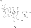
- FIG. 1 shows a schematic view of a laundry care appliance according to an embodiment of the present application.
- the laundry care appliance 100 shown is designed as a drum-free laundry care appliance 100 which, in contrast to conventional washing machines, does not have a rotating laundry drum for receiving the laundry.
- rotation of the rotatable laundry drum ensures that the laundry is effectively wetted with the washing liquid during the Washing process, and during a subsequent spin cycle ensures effective dehumidification of the laundry.
- the illustrated drum-free laundry care appliance 100 does not have a rotatable laundry drum for receiving the laundry, but instead a deformable laundry chamber 101 that can be closed in a fluid-tight manner for receiving the laundry.
- the deformable laundry chamber 101 is formed in particular from a reversibly deformable material, for example an elastomer, in order to ensure the deformability of the flexible laundry chamber 101 .
- the deformable laundry chamber 101 is thus designed as a fluid-tight, closable and deformable laundry chamber 101 .
- the deformable laundry chamber 101 has a first opening 103 which is fluidly connected to a first pump line 105 , the first pump line 105 in turn being fluidly connected to a pump 111 of the laundry care appliance 100 .
- the pump 111 is connected to a washing liquid tank 113 of the laundry care appliance 100 by a second pump line 109 .
- a drain line 115 branches off from the washing liquid tank 113 to a drain 117 .
- the first pump line 105 has a first valve 107-1 which can close the first opening 103 in a fluid-tight manner.
- the first valve 107-1 In a release position, the first valve 107-1 is the first opening 103 fluidically free and in a blocking position, the first valve 107-1 closes the first opening 103, the first opening 103 in particular at a chamber floor 101 - 1 of the deformable laundry chamber 101 facing the installation floor of the laundry care appliance 100 .
- the second pump line 109 has a second valve 107 - 2 which can block the second pump line 109 in terms of fluid technology.
- the second valve 107-2 fluidly releases the second pump line 109, and in a blocking position, the second valve 107-2 closes the second pump line 109.
- the pump 111 is designed to supply washing liquid from the washing liquid tank 113 through the first and second pump lines 105, 109 and through the first opening 103 to the deformable laundry chamber 101 during a supply process.
- the pump 111 is also designed to pump washing fluid out of the deformable laundry chamber 101 through the first opening 103, through the first pump line 105, and through the second pump line 109 into the washing liquid tank 113 during a pumping-out process, or to pump the pumped-out fluid from the washing liquid tank 113 through the Drain line 115 to drain 117 to pump.
- the pump 111 is designed to deliver fluid which, in addition to washing liquid, can also include air or a mixture of washing liquid and air.
- the pump 111 can therefore not only pump out the washing liquid received in the deformable laundry chamber 101 after the washing process, but also, in contrast to a drain pump used in conventional washing machines, also pump out air or a mixture of washing liquid and air from the deformable laundry chamber 101 , so as to create a partial vacuum in the deformable laundry chamber 101 .
- the pump 111 is formed as a liquid ring pump 111 in particular. Due to the resulting partial vacuum, the deformable Laundry chamber 101 is compressed to effectively dehumidify the laundry accommodated in the deformable laundry chamber 101 .
- the laundry care appliance 100 also has a washing liquid feed device 119 for feeding washing liquid, in particular fresh water, into the washing liquid tank 113, the washing liquid feed device 119 being fluidically connected to the washing liquid tank 113 by a feed line 121.
- the washing liquid supply device 119 can also be fluidically connected to the deformable laundry chamber 101 by a further supply line in order to supply the washing liquid, in particular fresh water or fresh water together with laundry care substance, directly to the deformable laundry chamber 101.
- the laundry care appliance 100 has a controller 123 which is connected to the pump 111 and the valves 107-1, 107-2 by control connections 125 and which is designed to control the pump 111 and the valves 107-1, 107 -2 to control.
- laundry care appliance 100 For further details regarding the laundry care appliance 100 according to the present disclosure, reference is made to the following explanations.
- FIG. 2 shows a schematic view of a laundry care appliance according to an embodiment of the present application.
- FIG. 2 shows a sectional view of a device insert 127 of a laundry care device 100, the device insert 127 being divided into an in 2 not shown housing of the laundry care appliance 100 can be inserted or pulled out of the housing in sections.
- the deformable laundry chamber 101 is arranged in the device insert 127 of the laundry care device 100 .
- the deformable laundry chamber 101 is formed from an elastomeric plastic, such as a silicone rubber.
- the device insert 127 has an insert housing 129 which delimits a device insert interior 130 of the device insert 127 , with the deformable laundry compartment 101 being arranged in the device insert interior 130 .
- the insert housing 129 of the appliance insert 127 is open at the top and the deformable laundry chamber 101 arranged in the insert housing 129 has a chamber opening 131 at the top.
- the insert housing 129 has an insert base 129-1 and a plurality of insert side walls 129-2, 129-3, 129-4, 129-5 connected to the insert base 129-1, wherein in the 2 only the first insert side wall 129-2, the second insert side wall 129-3, and the third insert side wall 129-4 are shown for reasons of illustration.
- the deformable laundry chamber 101 arranged in the appliance insert interior 130 has a chamber floor 101-1 facing the insert floor 129-1, the deformable laundry chamber 101 also having a plurality of chamber side walls 101-2, 101-3, 101-4, 101-5, which are connected to the chamber floor 101-1, wherein in the 2 For technical reasons, only the first chamber side wall 101-2, the second chamber side wall 101-3, and the third chamber side wall 101-4 are shown.
- the device insert 127 is shown in an extended position, in which the device insert 127 can be removed from the in 2 housing, not shown, is pulled out, and in which the user reaches into the deformable laundry chamber 101 in order, for example, to bring laundry into the deformable laundry chamber 101, or to remove laundry from the deformable laundry chamber 101.
- the laundry can be introduced into or removed from the deformable laundry chamber 101 through the chamber opening 131 .
- the chamber opening 131 is arranged on a top side of the deformable laundry chamber 101 that faces away from the chamber floor 101-1 of the deformable laundry chamber 101, so that a user of the laundry care appliance 100 in the pull-out position can advantageously and ergonomically pull the laundry from above through the chamber opening 131 can be introduced into the deformable laundry chamber 101, or can be removed from the deformable laundry chamber 101.
- the chamber opening 131 encompasses the entire top of the deformable laundry chamber 101, so that the laundry 130 can be introduced into the deformable laundry chamber 101 from above by the user without restrictions.
- the inside of the in 2 The non-illustrated housing of the laundry care appliance 100 has, on the top of the housing, in particular a 2 Housing cover, not shown, which is designed to close the chamber opening 131 in a fluid-tight manner when the device insert 127 is fully inserted into the housing.
- Washing liquid for the laundry care process can thus be supplied to the laundry chamber 101, which can be closed in a fluid-tight manner by the housing cover, or can be pumped out of the laundry chamber 101, which can be closed in a fluid-tight manner, after the laundry care process.
- the deformable laundry chamber 101 also has a first opening 103 which is arranged on the chamber floor 101 - 1 of the deformable laundry chamber 101 .
- the first opening 103 is fluidically connected to a first pump line 105, the first pump line 105 in turn having an in 2 non-illustrated pump 111 of the laundry care appliance 100 is fluidically connected in order to pump washing liquid out of the deformable laundry chamber 101 or to pump washing liquid into the deformable laundry chamber 101 .
- the fluid connection of the pump 111 is on the 1 referred.
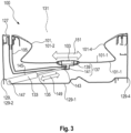
- FIG. 3 shows a schematic view of a laundry care appliance according to an embodiment of the present application.
- FIG. 3 is a sectional view of the appliance insert 127 of the laundry care appliance 100 along the sectional plane 132 of FIG 2 shown.
- the first opening 103 which is fluidically connected to the first pump line 105, is arranged on the chamber floor 101-1.
- the first opening 103 is connected to a fluid connector 137 for conducting fluid, the fluid connector 137 being disposed between the chamber floor 101-1 and the insert floor 129-1.
- the fluid connector 137 is connected to the deformable wash chamber 101 .
- the fluid connection element 137 serves for the fluid connection between the first pump line 105 and the first opening 103 formed in the deformable laundry chamber 101.
- the fluid connection element 137 has a drain section 139 which is fluidly connected to the first opening 103, and the fluid connection element 137 has a collection section 141 which is connected to the drain section 139 and is arranged on a side of the drain section 139 facing the tray 129-1 is.
- the collection section 141 has an in 3 unmarked plug-in socket, on which one end of the first pump line 105 is plugged.
- the laundry care appliance 100 has an actuator device 133, which is arranged between the chamber base 101-1 and the insert base 129-1, wherein the actuator device 133 has a displaceable actuator element 135, which is designed to be the deformable laundry chamber 101 in an oscillating movement to support the laundry care of laundry received in the deformable laundry chamber 101 .
- the displaceable actuator element 135 is connected in particular to the fluid connection element 137, in particular to the collecting section 141, in order to set the fluid connection element 137 and the deformable laundry chamber 101 connected to the fluid connection element 137 into an oscillating movement.
- an end of the displaceable actuator element 135 connected to the fluid connection element 137, in particular the collecting section 141, has a further pivotable hinge 143 in order to enable a pivoting movement of the displaceable actuator element 135 on the fluid connection element 137.
- the actuator device 133 has a fastening element 145 which is connected to the insert housing 129, in particular to the insert base 129-1, with the displaceable actuator element 135 of the actuator device 133 being connected to the fastening element 145.
- the actuator device 133 in particular the fastening element 145, comprises a hollow cylinder, the displaceable actuator element 135 comprising a piston which is displaceably mounted in the hollow cylinder in order to set the deformable laundry chamber 101 in an oscillating movement.
- the actuator device 133 comprises in particular a pneumatic combination of a hollow cylinder and a piston.
- the displaceable actuator element 13 in particular the piston that is displaceably mounted in the hollow cylinder, oscillates along a displacement direction 149 between an extended position and a retracted position to enable the deformable laundry chamber 101 in an oscillating movement.
- the oscillating movement of the deformable laundry chamber 101 resulting from the displacement movement of the displaceable actuator element 135 along the displacement direction 149 extends along an oscillation direction 151.
- the actuator device 133 as the actuator element 135 may not comprise a pneumatic combination of hollow cylinder and piston, but rather an eccentric element, with the eccentric element being rotated here in particular and thus having a displacement direction 149 extending along a circle in order to achieve a resulting to achieve oscillating movement of the deformable laundry chamber 101.
- the in 3 pump 111 (not shown), washing liquid or air is pumped out of the deformable laundry chamber 101, a partial vacuum is created within the deformable laundry chamber 101 when the chamber opening 131 of the deformable laundry chamber 101 is closed in an airtight manner, as a result of which the deformable laundry chamber 101 deforms, in particular contracts.
- the corresponding deformation or the corresponding contraction of the deformable laundry chamber 101 is characterized in particular by the fact that the chamber side walls 101-2 to 101-5 fold in at least in sections, so that the chamber floor 101-1 moves upwards, as is shown in 3 is shown schematically.
- the deformable laundry chamber 101 in particular lies against the laundry received in the deformable laundry chamber 101 .
- Laundry care appliance 100 has, in particular, a controller 123, which is connected in terms of control technology to actuator device 133, controller 123 being designed to control an amplitude and/or a frequency of the displacement movement of displaceable actuator element 135 along displacement device 149 in order to move the deformable laundry chamber 101 in an oscillating movement.
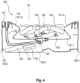
- FIG. 4 shows a schematic view of a laundry care appliance according to an embodiment of the present application.
- figure 5 shows a schematic view of a laundry care appliance according to an embodiment of the present application.
- a partial vacuum is present in the deformable laundry chamber 101, so that the deformable laundry chamber 101 is now compared to the 4 tightens stronger and to the laundry items accommodated in the deformable laundry chamber 101 advantageously applies.
- a housing cover 157 of the housing of the laundry care appliance 100 closes the chamber opening 31 of the deformable laundry chamber 101, so that a partial vacuum can be effectively maintained in the deformable laundry chamber 101.
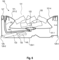
- FIG. 6 shows a schematic view of a laundry care appliance according to an embodiment of the present application.
- the 6 1 shows a state after the washing liquid has been pumped out of the deformable laundry chamber 101 by the pump 111, wherein the chamber opening 131 of the deformable laundry chamber 101 is open, and consequently there is no partial vacuum in the deformable laundry chamber 101.
- the oscillating movement of the deformable laundry chamber 101 which results from the oscillating movement of the displaceable actuator element 135 along the in 6 illustrated direction of displacement 149, the items of laundry 155 adhering to one another after the laundry care process are advantageously released from one another again, so that the user of the laundry care appliance 100 can easily remove them from the deformable laundry chamber 101.
Landscapes
- Engineering & Computer Science (AREA)
- Textile Engineering (AREA)
- Accessory Of Washing/Drying Machine, Commercial Washing/Drying Machine, Other Washing/Drying Machine (AREA)
Applications Claiming Priority (1)
| Application Number | Priority Date | Filing Date | Title |
|---|---|---|---|
| DE102022201562.2A DE102022201562A1 (de) | 2022-02-16 | 2022-02-16 | Wäschepflegegerät mit einer Aktoreinrichtung |
Publications (1)
| Publication Number | Publication Date |
|---|---|
| EP4230783A1 true EP4230783A1 (fr) | 2023-08-23 |
Family
ID=84982079
Family Applications (1)
| Application Number | Title | Priority Date | Filing Date |
|---|---|---|---|
| EP23152019.8A Withdrawn EP4230783A1 (fr) | 2022-02-16 | 2023-01-17 | Appareil de traitement du linge doté d'un dispositif actionneur |
Country Status (3)
| Country | Link |
|---|---|
| EP (1) | EP4230783A1 (fr) |
| CN (1) | CN116607301A (fr) |
| DE (1) | DE102022201562A1 (fr) |
Citations (5)
| Publication number | Priority date | Publication date | Assignee | Title |
|---|---|---|---|---|
| US3962892A (en) * | 1973-05-29 | 1976-06-15 | Garlinghouse Leslie H | Machine for controlled conditioning of liquids and mixtures |
| CN106480630A (zh) * | 2016-12-24 | 2017-03-08 | 张局 | 柔囊洗衣机 |
| WO2018222125A1 (fr) | 2017-06-02 | 2018-12-06 | Roderinno Ab | Lave-linge comportant un compartiment de lavage souple |
| WO2019205977A1 (fr) * | 2018-04-28 | 2019-10-31 | 青岛海尔滚筒洗衣机有限公司 | Appareil de traitement de vêtement |
| US20200216994A1 (en) | 2017-06-29 | 2020-07-09 | Roderinno Ab | Washing machine with a flexible washing compartment having one progressive intensity washing zone |
Family Cites Families (1)
| Publication number | Priority date | Publication date | Assignee | Title |
|---|---|---|---|---|
| DE102020208729A1 (de) | 2020-07-13 | 2022-01-13 | BSH Hausgeräte GmbH | Wäschepflegegerät mit einer Steuerung |
-
2022
- 2022-02-16 DE DE102022201562.2A patent/DE102022201562A1/de active Pending
-
2023
- 2023-01-17 EP EP23152019.8A patent/EP4230783A1/fr not_active Withdrawn
- 2023-02-16 CN CN202310121982.9A patent/CN116607301A/zh active Pending
Patent Citations (5)
| Publication number | Priority date | Publication date | Assignee | Title |
|---|---|---|---|---|
| US3962892A (en) * | 1973-05-29 | 1976-06-15 | Garlinghouse Leslie H | Machine for controlled conditioning of liquids and mixtures |
| CN106480630A (zh) * | 2016-12-24 | 2017-03-08 | 张局 | 柔囊洗衣机 |
| WO2018222125A1 (fr) | 2017-06-02 | 2018-12-06 | Roderinno Ab | Lave-linge comportant un compartiment de lavage souple |
| US20200216994A1 (en) | 2017-06-29 | 2020-07-09 | Roderinno Ab | Washing machine with a flexible washing compartment having one progressive intensity washing zone |
| WO2019205977A1 (fr) * | 2018-04-28 | 2019-10-31 | 青岛海尔滚筒洗衣机有限公司 | Appareil de traitement de vêtement |
Also Published As
| Publication number | Publication date |
|---|---|
| DE102022201562A1 (de) | 2023-08-17 |
| CN116607301A (zh) | 2023-08-18 |
Similar Documents
| Publication | Publication Date | Title |
|---|---|---|
| DE112007003791B4 (de) | Bekleidungstrockner | |
| EP3223675B1 (fr) | Dispositif d'essorage destiné à un appareil de nettoyage par voie humide et unité prémontable comportant le dispositif d'essorage | |
| DE102009004422A1 (de) | Türanordnung | |
| DE102019206182B4 (de) | Reiniger | |
| DE69610794T2 (de) | Haushaltbügeleinrichtung | |
| DE102022207949A1 (de) | Fluidführendes Haushaltsgerät | |
| DE102008050862A1 (de) | Trommelwaschmaschine | |
| WO2011138121A1 (fr) | Appareil ménager destiné à l'entretien de pièces de linge et comportant un tambour destiné à recevoir des pièces de linge | |
| EP4230783A1 (fr) | Appareil de traitement du linge doté d'un dispositif actionneur | |
| DE20304263U1 (de) | Behälter für Waschmittel und Waschmaschine mit einem solchen Behälter | |
| DE102009000920B4 (de) | Vorrichtung zum Auspressen von Reinigungselementen | |
| DE10065404B4 (de) | Auslaufeinrichtung für eine Waschmaschine | |
| DE102017112824A1 (de) | Vorrichtung zur Garraumreinigung | |
| EP3186430A1 (fr) | Dispositif de raccord de fluide pour appareil ménager et appareil ménager équipé de celui-ci | |
| DE2827254B2 (de) | Waschmaschine mit einer elektrisch antreibbaren Laugenpumpe | |
| DE102015212741B4 (de) | Wäschepflegegerät und Wäschepflegeverfahren | |
| DE10065344A1 (de) | Frontlader-Wäschebehandlungsmaschine | |
| DE202006010194U1 (de) | Waschmaschine | |
| EP4105375A1 (fr) | Appareil d'entretien du linge doté d'un dispositif de déformation | |
| EP4230784A1 (fr) | Appareil d'entretien du linge comprenant une chambre à linge déformable | |
| DE102022134552B4 (de) | Haushaltsgerät | |
| EP3387178B1 (fr) | Procédé de fonctionnement d'un appareil électroménager et appareil électroménager | |
| EP3280838A1 (fr) | Appareil d'entretien du linge comprenant un conduit d'évacuation | |
| DE19961456A1 (de) | Haushaltgerät | |
| BE1029571B1 (de) | Trommel für eine Waschmaschine und Waschmaschine |
Legal Events
| Date | Code | Title | Description |
|---|---|---|---|
| PUAI | Public reference made under article 153(3) epc to a published international application that has entered the european phase |
Free format text: ORIGINAL CODE: 0009012 |
|
| STAA | Information on the status of an ep patent application or granted ep patent |
Free format text: STATUS: THE APPLICATION HAS BEEN PUBLISHED |
|
| AK | Designated contracting states |
Kind code of ref document: A1 Designated state(s): AL AT BE BG CH CY CZ DE DK EE ES FI FR GB GR HR HU IE IS IT LI LT LU LV MC ME MK MT NL NO PL PT RO RS SE SI SK SM TR |
|
| STAA | Information on the status of an ep patent application or granted ep patent |
Free format text: STATUS: THE APPLICATION IS DEEMED TO BE WITHDRAWN |
|
| 18D | Application deemed to be withdrawn |
Effective date: 20240224 |