EP4231011B1 - Dispositifs et procédés pour les techniques de mesure de type patch clamp - Google Patents
Dispositifs et procédés pour les techniques de mesure de type patch clamp Download PDFInfo
- Publication number
- EP4231011B1 EP4231011B1 EP22157002.1A EP22157002A EP4231011B1 EP 4231011 B1 EP4231011 B1 EP 4231011B1 EP 22157002 A EP22157002 A EP 22157002A EP 4231011 B1 EP4231011 B1 EP 4231011B1
- Authority
- EP
- European Patent Office
- Prior art keywords
- patch clamp
- cleaning
- clamp electrodes
- sample
- attached
- Prior art date
- Legal status (The legal status is an assumption and is not a legal conclusion. Google has not performed a legal analysis and makes no representation as to the accuracy of the status listed.)
- Active
Links
Images

Classifications
-
- G—PHYSICS
- G01—MEASURING; TESTING
- G01N—INVESTIGATING OR ANALYSING MATERIALS BY DETERMINING THEIR CHEMICAL OR PHYSICAL PROPERTIES
- G01N35/00—Automatic analysis not limited to methods or materials provided for in any single one of groups G01N1/00 - G01N33/00; Handling materials therefor
- G01N35/00584—Control arrangements for automatic analysers
- G01N35/00594—Quality control, including calibration or testing of components of the analyser
- G01N35/00613—Quality control
- G01N35/00623—Quality control of instruments
-
- B—PERFORMING OPERATIONS; TRANSPORTING
- B01—PHYSICAL OR CHEMICAL PROCESSES OR APPARATUS IN GENERAL
- B01L—CHEMICAL OR PHYSICAL LABORATORY APPARATUS FOR GENERAL USE
- B01L13/00—Cleaning or rinsing apparatus
- B01L13/02—Cleaning or rinsing apparatus for receptacle or instruments
-
- B—PERFORMING OPERATIONS; TRANSPORTING
- B01—PHYSICAL OR CHEMICAL PROCESSES OR APPARATUS IN GENERAL
- B01L—CHEMICAL OR PHYSICAL LABORATORY APPARATUS FOR GENERAL USE
- B01L3/00—Containers or dishes for laboratory use, e.g. laboratory glassware; Droppers
- B01L3/02—Burettes; Pipettes
- B01L3/021—Pipettes, i.e. with only one conduit for withdrawing and redistributing liquids
- B01L3/0217—Pipettes, i.e. with only one conduit for withdrawing and redistributing liquids of the plunger pump type
- B01L3/022—Capillary pipettes, i.e. having very small bore
-
- B—PERFORMING OPERATIONS; TRANSPORTING
- B08—CLEANING
- B08B—CLEANING IN GENERAL; PREVENTION OF FOULING IN GENERAL
- B08B13/00—Accessories or details of general applicability for machines or apparatus for cleaning
-
- B—PERFORMING OPERATIONS; TRANSPORTING
- B08—CLEANING
- B08B—CLEANING IN GENERAL; PREVENTION OF FOULING IN GENERAL
- B08B3/00—Cleaning by methods involving the use or presence of liquid or steam
- B08B3/04—Cleaning involving contact with liquid
- B08B3/10—Cleaning involving contact with liquid with additional treatment of the liquid or of the object being cleaned, e.g. by heat, by electricity or by vibration
- B08B3/12—Cleaning involving contact with liquid with additional treatment of the liquid or of the object being cleaned, e.g. by heat, by electricity or by vibration by sonic or ultrasonic vibrations
-
- B—PERFORMING OPERATIONS; TRANSPORTING
- B08—CLEANING
- B08B—CLEANING IN GENERAL; PREVENTION OF FOULING IN GENERAL
- B08B7/00—Cleaning by methods not provided for in a single other subclass or a single group in this subclass
- B08B7/02—Cleaning by methods not provided for in a single other subclass or a single group in this subclass by distortion, beating, or vibration of the surface to be cleaned
- B08B7/026—Using sound waves
- B08B7/028—Using ultrasounds
-
- G—PHYSICS
- G01—MEASURING; TESTING
- G01N—INVESTIGATING OR ANALYSING MATERIALS BY DETERMINING THEIR CHEMICAL OR PHYSICAL PROPERTIES
- G01N33/00—Investigating or analysing materials by specific methods not covered by groups G01N1/00 - G01N31/00
- G01N33/48—Biological material, e.g. blood, urine; Haemocytometers
- G01N33/483—Physical analysis of biological material
- G01N33/487—Physical analysis of biological material of liquid biological material
- G01N33/48707—Physical analysis of biological material of liquid biological material by electrical means
- G01N33/48728—Investigating individual cells, e.g. by patch clamp, voltage clamp
-
- B—PERFORMING OPERATIONS; TRANSPORTING
- B01—PHYSICAL OR CHEMICAL PROCESSES OR APPARATUS IN GENERAL
- B01L—CHEMICAL OR PHYSICAL LABORATORY APPARATUS FOR GENERAL USE
- B01L2300/00—Additional constructional details
- B01L2300/06—Auxiliary integrated devices, integrated components
- B01L2300/0627—Sensor or part of a sensor is integrated
- B01L2300/0645—Electrodes
-
- B—PERFORMING OPERATIONS; TRANSPORTING
- B01—PHYSICAL OR CHEMICAL PROCESSES OR APPARATUS IN GENERAL
- B01L—CHEMICAL OR PHYSICAL LABORATORY APPARATUS FOR GENERAL USE
- B01L2400/00—Moving or stopping fluids
- B01L2400/04—Moving fluids with specific forces or mechanical means
- B01L2400/0403—Moving fluids with specific forces or mechanical means specific forces
- B01L2400/0433—Moving fluids with specific forces or mechanical means specific forces vibrational forces
- B01L2400/0439—Moving fluids with specific forces or mechanical means specific forces vibrational forces ultrasonic vibrations, vibrating piezo elements
Definitions
- the present invention relates to improved devices and methods for detecting one or more characteristics of cells with patch clamp electrodes, wherein the used patch clamp electrodes are cleaned by application of ultrasonic vibrations, and uses of the devices and methods.
- the current flow through the individual ion channels in the cell membrane of a cell is measured.
- the current strengths are in the picoampere range.
- an electrode with a very small aperture approximately 1 ⁇ m
- the cell membrane is pulled a little way into the electrode by means of negative pressure so that an electrically tight connection is made between the glass edge and the cell membrane.
- part of the membrane usually remains on (or in) the electrode. With this contamination it is not possible to achieve a tight connection between the electrode and a new cell again. As a rule, the electrode is now exchanged for a new one.
- temperatures are given as degrees Celsius (°C).
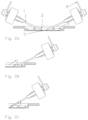
- One particular embodiment of the present invention is directed to a device for detecting one or more characteristics of biological, preferably living, cells comprising or consisting of: a chamber insertion tray into which at least one, preferably one, sample examination chamber and one or more cleaning chambers can be securely inserted, preferably at fixed locations; one or more, preferably 1 to 12, patch clamp electrodes, wherein the patch clamp electrodes are pipettes, each one having attached to its respective rear end (the end distant from the sample examination chamber) a pressure/vacuum port and an electrode holder with which the respective patch clamp electrode is held.
- the patch clamp electrodes can also be referred to as micropipettes or patch pipettes, as is known in the art.
- the chambers that are used in the present invention can be pre-prepared, as the device of the present invention is intended to be modular, and can be inserted, removed and/or replaced depending on the desired purpose or necessities at any time (as long as not an actual measurement is conducted in/with that chamber).
- the chambers can be of various shapes and sizes but need to be able to be inserted to the insertion tray. They can have Petri dish-like shapes, bowl-like shape, cup-like shape, plate-like shape, or any other shape as long as sufficient room is present at its bottom for the necessary sample or the necessary amount of cleaning liquid; in some preferred embodiments the shape would resemble that of Petri dishes.
- the chambers are indeed Petri dishes, whose lids are removed before taking measurements or cleaning action or other lidded vessels.
- Such configuration has the advantage that the sample or cleaning liquid can be protected as long as possible and is only subjected to the environment for as longs as absolutely needed (the lid can be replaced after measurements or cleaning).
- the lids may also be provided with openings through which the electrodes/pipettes can be inserted in the chambers.
- the chambers can optionally be fixed in place with the insertion tray either via friction, if the sizes are closely matched to insertions/recesses in the tray or via fixation elements. These fixation elements can be magnets; particularly if the chambers are made of metal (which is also one possibility for also being the reference electrode - vide infra), screws, clamps, adhesives or the like.
- the chamber insertion tray is configured such that it can hold at least one sample examination chamber and at least one cleaning chamber.
- the exact number of chambers it can hold (or actually holds, if it could hold more) is determined by the respective desires and/or necessities based on what kind and how many measurements should be done.
- the most basic chamber insertion tray in the context of the present invention would hold one examination chamber and one cleaning chamber.
- a further example would hold one examination chamber and two cleaning chamber, which might be (directly) adjacent to each other or lie on opposite sides with the examination chamber between them or at any desired angle between them (if the tray is considered a circle for this determination purpose).
- the device comprises one or more ultrasonic generation devices configured to provide ultrasonic vibrations to each of the one or more patch clamp electrodes.
- the one or more ultrasonic generation devices are either attached to one or more, preferably all of the electrode holders, or are attached to one or more, preferably all, of the cleaning chambers, or are both attached to one or more, preferably all of the electrode holders, and to one or more, preferably all, of the cleaning chambers.
- the ultrasonic generation devices are either attached to one or more, preferably all of the electrode holders, and are particularly integral part of the holders or holder structure.
- the one or more ultrasonic generation devices are piezo-based ultrasonic generation devices, particularly piezo actuators.
- piezo actuators are based on crystals which change their outer dimension when a voltage is applied, as is known to the person skilled in the art.
- Piezo actuators can be used as all-ceramics and also, preferably multi-layer crystals.
- Preferred multilayer piezo actuators than can be employed according to the present invention have operating voltages of from -40 to 120 V, preferably -20 to 100 V, an operating temperature of between -60 and 200°C, preferably between -40 and 150°C. While the exact sizes of the piezo actuators that can be employed according to the present invention can be chosen in dependence of the size of the entire device, which, in turn, depends on the exact usage, it is preferred in some embodiments if the actuators have a size of from 1x1x1 mm to 4x4x4 mm, particularly 2x2x2 mm. These have preferably travel ranges of between 1 ⁇ m and 5 ⁇ m, more preferably 1.5 ⁇ m to 3 ⁇ m, and particularly 2 ⁇ m to 2.5 ⁇ m.
- these actuators show an axial resonant frequency measured at 1 V(pp) of more than 500 kH7, particularly more than 600 kHz, and an electrical capacitance measured at 1V(pp), 1kHz, RT of 15 to 40 nF, preferably 20 to 30 nF, particularly 25 nF.
- piezo actuators of the described kind that can be employed in the present invention are commercially available from PI (physics instruments).
- the patch clamp electrodes have at their front end, which is the end with which they would contact the biological cell(s) in the sample examination chamber, have an apertured surface configured to be able to form a resistance seal with a membrane of a biological cell.
- That aperture surface usually is a round hole (as is usual for pipettes) having preferably a diameter of 0.5 to 2 ⁇ m, preferably 0.8 to 2 ⁇ m, further preferably 0.5 to 1.5 ⁇ m, further preferably a diameter of 1.8 to 1.2 ⁇ m, particularly preferred 0.9 to 1.1 ⁇ m and especially about 1 ⁇ m, and a wall thickness of between 0.05 to 0.25 ⁇ m, preferably 0.1 to 2 ⁇ m and particularly 0.15 ⁇ m.
- control device is configured to, in the case of more than one ultrasonic generation devices, control the respective ultrasonic generation devices either synchronously or asynchronously.
- the control device employed in the present invention preferably positions the patch clamp electrode (pipette) to the cleaning position using a positioning system.
- Ultrasound is active during the over- under- pressure sequence.
- the Ultrasound frequency can be pre-set freely or controlled to achieve the best cleaning result.
- the transmission of light UV, IR, visible
- the frequency and the duration of the application of the ultrasonic vibration be controlled depending on that.
- a previously programmed sequence with overpressure and under pressure runs parallel and is controlled by the control device. Duration, pressure strength and repetitions of the overpressure and under pressure can be programmed. After cleaning is completed, the patch clamp electrode (pipette) is repositioned to any desired position by control device.
- the device of the present invention can be controlled by a microcontroller system with a dedicated software specifically designed and programmed for that purpose to create the ultrasound signal, trigger the over-/ under pressure and the positioning.
- One further specific embodiment of the present invention is directed to a method for detecting one or more characteristics of biological, preferably living, cells comprising or consisting of the following steps:
- non-toxic solution should not harm, inhibit or suppress chemical reactions or electrophysiological responses from a single neuron.
- Many of the cleaning solutions used in the prior art in the concentrations they are used to clean electrodes/pipettes can be harmful or toxic to living cells.
- the device/system of the present invention is able to clean the patch clamp electrodes (pipettes) without such g solutions, preferably using only the solution of the bath (ACSF) or just water, particularly deionized water or tap water.
- ACSF solution of the bath
- the ultrasonic vibrations are transmitted to the used one or more patch clamp electrodes by applying ultrasonic vibrations via ultrasonic generation devices,
- some embodiments of the present invention are directed to the use of the device according the present invention or the method according to the present invention to detect one or more characteristics of biological, preferably living, cells.
- the invention is not restricted to the employment of piezo devices and other methods for generating ultrasonic vibrations are also envisioned by the present application.
- the patch clamp electrodes i.e. the pipettes
- the substances adhering to the surfaces of these, particularly cellular residues are shaken loose and can easily be ejected from the patch clamp electrodes, i.e. the pipettes, by applying alternating over- und underpressure to them, optionally with the aid of water.
- the ultrasonic vibrations directly to the patch clamp electrodes, i.e. the pipettes, e.g. if the ultrasonic generating device is part of the electrode holder.
- the ultrasonic vibrations in that they are applied to the cleaning chamber, in which water is present and the patch clamp electrodes, i.e. the pipettes, are partly (with their front ends, i.e. tips) immersed in this water.
- the vibrations transmitted by the water are sufficient to achieve this cleaning effect, particularly, if the water is alternatingly sucked in and blown out of the patch clamp electrodes, i.e. the pipettes, by application of alternating under- and overpressure.
- the direct application of the ultrasonic vibration to the patch clamp electrodes, i.e. the pipettes is preferred.
- the utilization of a cleaning solution that dissolves or removes all these residues from the surfaces of the patch clamp electrodes, i.e. the pipettes, is not necessary anymore and can be disposed of.
- the solution of the present invention provides for an easier to conduct, easier to manufacture and cheaper solution than the prior art.
- the present invention is highly beneficial under ecological aspects as no toxic cleaning solutions are needed.
- one or more piezo actuators are pressed against the outer surface of a patch clamp electrode, i.e. pipette, so that upon activation of the actuators, the actuators cause the patch clamp electrode, i.e. pipette, to swing by the application of a corresponding current impulse.
- Frequency and amplitude can be adjustable or can be fixed. If there are several actuators, the control can be synchronous or asynchronous. The oscillation excitation of the electrode takes place during the cleaning process.
- two piezo actuators are used per patch clamp electrode, i.e. pipette.
- the cleaning chamber is provided with the same physiological solution as the examination chamber containing the sample or with a non-toxic cleaning solution, particularly water.
- each of the respective patch clamp electrodes i.e. pipettes
- a contamination of one the patch clamp electrodes i.e. pipettes
- the device of the present invention also includes an additional bath electrode or reference electrode.
- the examination chamber is configured to be the reference electrode, and is therefore made of a material that is electrically conductive, or the examination chamber has at least one electrically conducting part or section that acts as reference electrode.
- the present invention is directed to a method for cleaning used patch clamp electrodes comprising or consisting of the steps
- the ultrasonic vibrations are transmitted to the used one or more patch clamp electrodes by applying ultrasonic vibrations via ultrasonic generation devices.
- These ultrasonic generation devices can, similarly as outlined above, be attached to or being part of electrode holders attached to one or more, preferably all, of the patch clamp electrodes and or to one or more, preferably all, of the cleaning chambers.
- the cleaning with the ultrasonic vibrations is done with the aid of the same physiological solution as the examination chamber containing the sample or with a non-toxic cleaning solution, particularly water, especially particularly deionised, water. Further particularly the cleaning is done with the aid of the same physiological solution as the examination chamber containing the sample or with water, the latter of which can be tap water or deionized water.
- a patch clamp electrode which basically is or can be a hollow glass tube (also known as a micropipette or patch pipette) filled with an electrolyte solution and a recording electrode connected to an amplifier, is brought into contact with the membrane of an isolated cell.
- Another electrode is placed in a bath surrounding the cell or tissue as a reference ground electrode (or the vessel of the bath itself is used as reference electrode).
- An electrical circuit can be formed between the recording and reference electrode with the cell of interest in between.
- One advantage of the present invention is the fact that the outsides of the patch clamp electrodes (pipettes) do not need to be rinsed, while in systems according to the prior art they need to be as cleaning solutions adheres to the outsides and must be removed prior to reusing the electrode (pipette).
- the dimensions of the system regarding, inter alia, insertion tray, chambers, ultrasonic generation devices and pressure system, are scalable. By that the system can be easily customized to the respective demands of the scientist.
- the cleaning of the devices according to the present with the process according to the invention provides for excellent cleaning without the need for additional cleaning solution.
Landscapes
- Health & Medical Sciences (AREA)
- Engineering & Computer Science (AREA)
- Life Sciences & Earth Sciences (AREA)
- Biomedical Technology (AREA)
- Chemical & Material Sciences (AREA)
- Physics & Mathematics (AREA)
- Analytical Chemistry (AREA)
- Pathology (AREA)
- Immunology (AREA)
- General Physics & Mathematics (AREA)
- General Health & Medical Sciences (AREA)
- Biochemistry (AREA)
- Quality & Reliability (AREA)
- Medicinal Chemistry (AREA)
- Food Science & Technology (AREA)
- Urology & Nephrology (AREA)
- Molecular Biology (AREA)
- Hematology (AREA)
- Biophysics (AREA)
- Clinical Laboratory Science (AREA)
- Chemical Kinetics & Catalysis (AREA)
- Automatic Analysis And Handling Materials Therefor (AREA)
- Sampling And Sample Adjustment (AREA)
- Investigating Or Analysing Biological Materials (AREA)
Claims (10)
- Dispositif de détection d'une ou plusieurs caractéristiques de cellules biologiques, comprenant :- un plateau d'insertion de chambre (6) dans lequel au moins une chambre d'examen d'échantillons (2) et une ou plusieurs chambres de nettoyage (5) sont insérées de manière sécurisée ;- une ou plusieurs électrodes patch-clamp (1), dans lequel les électrodes patch-clamp sont des pipettes comportant chacune, attachés à son extrémité arrière respective, un orifice de pression/vide (8) et un porte-électrode (4) qui supporte l'électrode patch-clamp (1) respective ;dans lequel le dispositif comprend un ou plusieurs dispositifs de génération d'ultrasons (7) configurés pour délivrer des vibrations ultrasonores à chacune desdites une ou plusieurs électrodes patch-clamp (1),caractérisé en ce que lesdits un ou plusieurs dispositifs de génération d'ultrasons (7) sont- attachés à un ou plusieurs desdits porte-électrodes (4), et de préférence à tous ceux-ci, ou- attachés à une ou plusieurs desdites chambres de nettoyage (5), et de préférence à toutes celles-ci, ou- attachés à un ou plusieurs desdits porte-électrodes (4), et de préférence à tous ceux-ci, et à une ou plusieurs desdites chambres de nettoyage (5), et de préférence à toutes celles-ci.
- Dispositif selon la revendication 1, caractérisé en ce que lesdits un ou plusieurs dispositifs de génération d'ultrasons (7) sont des dispositifs de génération d'ultrasons piézoélectriques, en particulier des actionneurs piézoélectriques.
- Dispositif selon l'une quelconque des revendications précédentes, caractérisé en ce que les électrodes patch-clamp (1) présentent à leur extrémité avant une surface ajourée configurée pour pouvoir former un joint résistif avec une membrane d'une cellule biologique.
- Dispositif selon l'une quelconque des revendications précédentes, caractérisé en ce que le dispositif comprend un dispositif de contrôle configuré pour fournir des instructions de contrôle au moins- aux électrodes patch-clamp (1), de préférence via les porte-électrodes (4), et/ou- aux dispositifs de génération d'ultrasons (7).
- Dispositif selon l'une quelconque des revendications précédentes, caractérisé en ce que le dispositif de contrôle est configuré pour, dans le cas de plusieurs dispositifs de génération d'ultrasons (7), contrôler les dispositifs de génération d'ultrasons (7) respectifs de manière soit synchrone, soit asynchrone.
- Procédé de détection d'une ou plusieurs caractéristiques de cellules biologiques, comprenant :A) la fourniture d'un dispositif comportant un plateau d'insertion de chambre dans lequel au moins une chambre d'examen d'échantillons (2) et une ou plusieurs chambres de nettoyage (5) sont insérées de manière sécurisée ;B) la fourniture, à ladite au moins une chambre d'examen d'échantillons (2), d'un échantillon (3) contenant une ou plusieurs cellules biologiques ;C) la mise en contact de l'échantillon (3) avec une ou plusieurs électrodes patch-clamp (1) propres, dans lequel les électrodes patch-clamp sont des pipettes, et la mesure d'une ou plusieurs caractéristiques via les électrodes patch-clamp (1) ;D) l'enlèvement desdites une ou plusieurs électrodes patch-clamp (1) de l'échantillon (3) et de la chambre d'examen d'échantillons (2) et le transfert desdites une ou plusieurs électrodes patch-clamp (1) usagées dans lesdites une ou plusieurs chambres de nettoyage (5) ;E) le nettoyage desdites une ou plusieurs électrodes patch-clamp (1) dans lesdites une ou plusieurs chambres de nettoyage (5) ;F) facultativement, après le nettoyage, la répétition des étapes C) à E) avec le même échantillon ou avec un nouvel échantillon, en utilisant lesdites une ou plusieurs électrodes patch-clamp (1) nettoyées ;dans lequel lesdites une ou plusieurs électrodes patch-clamp (1) usagées sont nettoyées en transmettant des vibrations ultrasonores auxdites une ou plusieurs électrodes patch-clamp (1) usagées,caractérisé en ce que les vibrations ultrasonores sont transmises auxdites une ou plusieurs électrodes patch-clamp (1) usagées en appliquant des vibrations ultrasonores via des dispositifs de génération d'ultrasons (7)- attachés à ou intégrés dans des porte-électrodes (4) attachés à une ou plusieurs desdites électrodes patch-clamp (1), et de préférence à toutes celles-ci ; ou- attachés à une ou plusieurs desdites chambres de nettoyage (5), et de préférence à toutes celles-ci, ou- attachés à ou intégrés dans des porte-électrodes (4) attachés à une ou plusieurs desdites électrodes patch-clamp (1), et de préférence à toutes celles-ci, et attachés à une ou plusieurs desdites chambres de nettoyage (5), et de préférence à toutes celles-ci.
- Procédé selon la revendication 6, caractérisé en ce que le nettoyage par vibrations ultrasonores est effectué à l'aide de la même solution physiologique que celle de la chambre d'examen contenant l'échantillon, ou à l'aide d'une solution de nettoyage non toxique, en particulier de l'eau, et plus en particulier de l'eau déionisée, ou en ce que le nettoyage est effectué à l'aide de la même solution physiologique que celle de la chambre d'examen contenant l'échantillon ou avec de l'eau, cette dernière étant soit de l'eau du robinet, soit de l'eau déionisée.
- Procédé de nettoyage d'électrodes patch-clamp usagées comprenant les étapes suivantes ou consistant en celles-ci :a) fourniture d'un dispositif comportant une ou plusieurs chambres de nettoyage (5) ;d) enlèvement d'une ou plusieurs électrodes patch-clamp (1), dans lequel les électrodes patch-clamp sont des pipettes, d'un échantillon (3), et transfert desdites une ou plusieurs électrodes patch-clamp (1) usagées dans lesdites une ou plusieurs chambres de nettoyage (5) ;e) nettoyage desdites une ou plusieurs électrodes patch-clamp (1) dans lesdites une ou plusieurs chambres de nettoyage (5) ;dans lequel lesdites une ou plusieurs électrodes patch-clamp (1) usagées sont nettoyées en transmettant des vibrations ultrasonores auxdites une ou plusieurs électrodes patch-clamp (1) usagées,caractérisé en ce que les vibrations ultrasonores sont transmises auxdites une ou plusieurs électrodes patch-clamp (1) usagées en appliquant des vibrations ultrasonores via des dispositifs de génération d'ultrasons (7)- attachés à ou intégrés dans des porte-électrodes (4) attachés à une ou plusieurs desdites électrodes patch-clamp (1), et de préférence à toutes celles-ci, ou- attachés à une ou plusieurs desdites chambres de nettoyage (5), et de préférence à toutes celles-ci, ou- attachés à ou intégrés dans des porte-électrodes (4) attachés à une ou plusieurs desdites électrodes patch-clamp (1), et de préférence à toutes celles-ci, et attachés à une ou plusieurs desdites chambres de nettoyage (5), et de préférence à toutes celles-ci.
- Procédé selon la revendication 8, caractérisé en ce que le nettoyage par vibrations ultrasonores est effectué à l'aide de la même solution physiologique que celle de la chambre d'examen contenant l'échantillon, ou à l'aide d'une solution de nettoyage non toxique, en particulier de l'eau, et plus en particulier de l'eau déionisée, ou en ce que le nettoyage est effectué à l'aide de la même solution physiologique que celle de la chambre d'examen contenant l'échantillon ou avec de l'eau, cette dernière étant soit de l'eau du robinet, soit de l'eau déionisée.
- Utilisation du dispositif selon l'une quelconque des revendications 1 à 5 ou du procédé selon l'une quelconque des revendications 6 et 7 pour détecter une ou plusieurs caractéristiques de cellules biologiques, de préférence vivantes.
Priority Applications (3)
| Application Number | Priority Date | Filing Date | Title |
|---|---|---|---|
| EP22157002.1A EP4231011B1 (fr) | 2022-02-16 | 2022-02-16 | Dispositifs et procédés pour les techniques de mesure de type patch clamp |
| US18/166,613 US12298321B2 (en) | 2022-02-16 | 2023-02-09 | Devices and methods for patch clamp measurement techniques |
| CN202310104576.1A CN116609519A (zh) | 2022-02-16 | 2023-02-13 | 用于膜片钳测量技术的装置和方法 |
Applications Claiming Priority (1)
| Application Number | Priority Date | Filing Date | Title |
|---|---|---|---|
| EP22157002.1A EP4231011B1 (fr) | 2022-02-16 | 2022-02-16 | Dispositifs et procédés pour les techniques de mesure de type patch clamp |
Publications (3)
| Publication Number | Publication Date |
|---|---|
| EP4231011A1 EP4231011A1 (fr) | 2023-08-23 |
| EP4231011B1 true EP4231011B1 (fr) | 2025-07-09 |
| EP4231011C0 EP4231011C0 (fr) | 2025-07-09 |
Family
ID=80682537
Family Applications (1)
| Application Number | Title | Priority Date | Filing Date |
|---|---|---|---|
| EP22157002.1A Active EP4231011B1 (fr) | 2022-02-16 | 2022-02-16 | Dispositifs et procédés pour les techniques de mesure de type patch clamp |
Country Status (3)
| Country | Link |
|---|---|
| US (1) | US12298321B2 (fr) |
| EP (1) | EP4231011B1 (fr) |
| CN (1) | CN116609519A (fr) |
Family Cites Families (9)
| Publication number | Priority date | Publication date | Assignee | Title |
|---|---|---|---|---|
| US4861332A (en) * | 1986-04-14 | 1989-08-29 | Ultramed Corporation | Ultrasonic probe |
| NZ337814A (en) | 1997-05-01 | 2001-04-27 | Neurosearch As | Patch clamp apparatus with means for automatically connecting electrode to a cell |
| EP1178315A1 (fr) * | 2000-07-31 | 2002-02-06 | Albrecht Dr.med. Priv.Doz. Lepple-Wienhues | Dispositif et procédé pour examiner des cellules à l'aide de la méthode patch-clamp |
| US7112433B2 (en) * | 2003-04-24 | 2006-09-26 | Hewlett-Packard Development Company, L.P. | Electrical analysis of biological membranes |
| US10830758B2 (en) | 2015-08-09 | 2020-11-10 | Georgia Tech Research Corporation | Systems and methods enabling patch-clamp re-use |
| US10859687B2 (en) * | 2016-03-31 | 2020-12-08 | Butterfly Network, Inc. | Serial interface for parameter transfer in an ultrasound device |
| EP3967404A3 (fr) | 2016-08-09 | 2022-06-22 | Georgia Tech Research Corporation | Systèmes et procédés permettant la réutilisation d'un dispositif de patch-clamp |
| CN211757274U (zh) * | 2020-01-02 | 2020-10-27 | 上海信谊万象药业股份有限公司 | 一种移液管超声波清洗装置 |
| CN113663751A (zh) * | 2021-07-09 | 2021-11-19 | 宁夏金域医学检验所(有限公司) | 一种实验室多功能移液枪支架 |
-
2022
- 2022-02-16 EP EP22157002.1A patent/EP4231011B1/fr active Active
-
2023
- 2023-02-09 US US18/166,613 patent/US12298321B2/en active Active
- 2023-02-13 CN CN202310104576.1A patent/CN116609519A/zh active Pending
Also Published As
| Publication number | Publication date |
|---|---|
| EP4231011A1 (fr) | 2023-08-23 |
| EP4231011C0 (fr) | 2025-07-09 |
| CN116609519A (zh) | 2023-08-18 |
| US20230258666A1 (en) | 2023-08-17 |
| US12298321B2 (en) | 2025-05-13 |
Similar Documents
| Publication | Publication Date | Title |
|---|---|---|
| US6638743B2 (en) | Method for measuring a state variable | |
| EP1707222B1 (fr) | Controle d'un procédé de nettoyage | |
| CN112203765B (zh) | 用于进行电测量的设备 | |
| EP1254366B1 (fr) | Detecteur electrochimique pour la detection specifique d'acide peracetique dans des solutions aqueuses utilisant des methodes amperometriques pulsees | |
| US12085559B2 (en) | Replaceable ground electrode for electrophysiology, electrode rejuvenating apparatus, and related methods and systems | |
| ATE44131T1 (de) | Verfahren und vorrichtung zur reinigung, desinfektion und sterilisation von aerztlichen, insbesondere zahnaerztlichen instrumenten. | |
| EP1709979B1 (fr) | Indicateur de nettoyage pour surveillance du processus de nettoyage | |
| Stett et al. | Patch-clamping of primary cardiac cells with micro-openings in polyimide films | |
| ES2894672T3 (es) | Proceso para determinar la viabilidad de microorganismos de ensayo de un indicador biológico y dispositivo de detección de la esterilización para su determinación | |
| ES2813583T3 (es) | Condensador para detectar microorganismos viables | |
| EP4231011B1 (fr) | Dispositifs et procédés pour les techniques de mesure de type patch clamp | |
| WO2020044978A1 (fr) | Dispositif de mesure et procédé d'évaluation | |
| Garner et al. | Time domain dielectric spectroscopy measurements of HL-60 cell suspensions after microsecond and nanosecond electrical pulses | |
| ES2894970T3 (es) | Proceso para determinar la viabilidad de microorganismos de ensayo de un indicador biológico y dispositivo de detección de la esterilización para su determinación | |
| Hara et al. | An electrochemical investigation of the impact of microfabrication techniques on polymer-based microelectrode neural interfaces | |
| JPWO2009128346A1 (ja) | 電極モジュール | |
| Oliver et al. | An impedimetric sensor for monitoring the growth of Staphylococcus epidermidis | |
| US20210072223A1 (en) | Sample Testing Systems And Methods | |
| ES2894682T3 (es) | Proceso para determinar la viabilidad de microorganismos de ensayo de un indicador biológico y dispositivo de detección de la esterilización para su determinación | |
| JP7442813B2 (ja) | 感受性測定装置、及び、感受性測定方法 | |
| EP3394283B1 (fr) | Systèmes et procédés permettant la réutilisation d'un dispositif de patch-clamp | |
| Sutton et al. | Numerical simulation of the time-dependent current to membrane-covered oxygen sensors. Part IV. Experimental verification that the switch-on transient is non-Cottrellian for microdisc electrodes | |
| Py et al. | Priming and testing silicon patch-clamp neurochips | |
| Ayala et al. | A new cell-on-chip impedometric interface: Design, implementation and experimental results | |
| JP4516356B2 (ja) | シス−トランス液流方式によるイオンチャネル解析方法と、その方法に使用するイオンチャネル解析装置 |
Legal Events
| Date | Code | Title | Description |
|---|---|---|---|
| PUAI | Public reference made under article 153(3) epc to a published international application that has entered the european phase |
Free format text: ORIGINAL CODE: 0009012 |
|
| STAA | Information on the status of an ep patent application or granted ep patent |
Free format text: STATUS: REQUEST FOR EXAMINATION WAS MADE |
|
| 17P | Request for examination filed |
Effective date: 20230324 |
|
| AK | Designated contracting states |
Kind code of ref document: A1 Designated state(s): AL AT BE BG CH CY CZ DE DK EE ES FI FR GB GR HR HU IE IS IT LI LT LU LV MC MK MT NL NO PL PT RO RS SE SI SK SM TR |
|
| RBV | Designated contracting states (corrected) |
Designated state(s): AL AT BE BG CH CY CZ DE DK EE ES FI FR GB GR HR HU IE IS IT LI LT LU LV MC MK MT NL NO PL PT RO RS SE SI SK SM TR |
|
| GRAP | Despatch of communication of intention to grant a patent |
Free format text: ORIGINAL CODE: EPIDOSNIGR1 |
|
| STAA | Information on the status of an ep patent application or granted ep patent |
Free format text: STATUS: GRANT OF PATENT IS INTENDED |
|
| INTG | Intention to grant announced |
Effective date: 20241212 |
|
| GRAJ | Information related to disapproval of communication of intention to grant by the applicant or resumption of examination proceedings by the epo deleted |
Free format text: ORIGINAL CODE: EPIDOSDIGR1 |
|
| STAA | Information on the status of an ep patent application or granted ep patent |
Free format text: STATUS: REQUEST FOR EXAMINATION WAS MADE |
|
| GRAP | Despatch of communication of intention to grant a patent |
Free format text: ORIGINAL CODE: EPIDOSNIGR1 |
|
| STAA | Information on the status of an ep patent application or granted ep patent |
Free format text: STATUS: GRANT OF PATENT IS INTENDED |
|
| INTC | Intention to grant announced (deleted) | ||
| INTG | Intention to grant announced |
Effective date: 20250210 |
|
| GRAS | Grant fee paid |
Free format text: ORIGINAL CODE: EPIDOSNIGR3 |
|
| GRAA | (expected) grant |
Free format text: ORIGINAL CODE: 0009210 |
|
| STAA | Information on the status of an ep patent application or granted ep patent |
Free format text: STATUS: THE PATENT HAS BEEN GRANTED |
|
| AK | Designated contracting states |
Kind code of ref document: B1 Designated state(s): AL AT BE BG CH CY CZ DE DK EE ES FI FR GB GR HR HU IE IS IT LI LT LU LV MC MK MT NL NO PL PT RO RS SE SI SK SM TR |
|
| REG | Reference to a national code |
Ref country code: GB Ref legal event code: FG4D |
|
| REG | Reference to a national code |
Ref country code: CH Ref legal event code: EP |
|
| REG | Reference to a national code |
Ref country code: IE Ref legal event code: FG4D |
|
| REG | Reference to a national code |
Ref country code: DE Ref legal event code: R096 Ref document number: 602022017149 Country of ref document: DE |
|
| U01 | Request for unitary effect filed |
Effective date: 20250723 |
|
| U07 | Unitary effect registered |
Designated state(s): AT BE BG DE DK EE FI FR IT LT LU LV MT NL PT RO SE SI Effective date: 20250729 |
|
| REG | Reference to a national code |
Ref country code: CH Ref legal event code: R17 Free format text: ST27 STATUS EVENT CODE: U-0-0-R10-R17 (AS PROVIDED BY THE NATIONAL OFFICE) Effective date: 20251001 |
|
| PG25 | Lapsed in a contracting state [announced via postgrant information from national office to epo] |
Ref country code: IS Free format text: LAPSE BECAUSE OF FAILURE TO SUBMIT A TRANSLATION OF THE DESCRIPTION OR TO PAY THE FEE WITHIN THE PRESCRIBED TIME-LIMIT Effective date: 20251109 |
|
| PG25 | Lapsed in a contracting state [announced via postgrant information from national office to epo] |
Ref country code: NO Free format text: LAPSE BECAUSE OF FAILURE TO SUBMIT A TRANSLATION OF THE DESCRIPTION OR TO PAY THE FEE WITHIN THE PRESCRIBED TIME-LIMIT Effective date: 20251009 |
|
| PG25 | Lapsed in a contracting state [announced via postgrant information from national office to epo] |
Ref country code: HR Free format text: LAPSE BECAUSE OF FAILURE TO SUBMIT A TRANSLATION OF THE DESCRIPTION OR TO PAY THE FEE WITHIN THE PRESCRIBED TIME-LIMIT Effective date: 20250709 |
|
| PG25 | Lapsed in a contracting state [announced via postgrant information from national office to epo] |
Ref country code: GR Free format text: LAPSE BECAUSE OF FAILURE TO SUBMIT A TRANSLATION OF THE DESCRIPTION OR TO PAY THE FEE WITHIN THE PRESCRIBED TIME-LIMIT Effective date: 20251010 |
|
| PG25 | Lapsed in a contracting state [announced via postgrant information from national office to epo] |
Ref country code: PL Free format text: LAPSE BECAUSE OF FAILURE TO SUBMIT A TRANSLATION OF THE DESCRIPTION OR TO PAY THE FEE WITHIN THE PRESCRIBED TIME-LIMIT Effective date: 20250709 |
|
| PG25 | Lapsed in a contracting state [announced via postgrant information from national office to epo] |
Ref country code: RS Free format text: LAPSE BECAUSE OF FAILURE TO SUBMIT A TRANSLATION OF THE DESCRIPTION OR TO PAY THE FEE WITHIN THE PRESCRIBED TIME-LIMIT Effective date: 20251009 |
|
| PG25 | Lapsed in a contracting state [announced via postgrant information from national office to epo] |
Ref country code: ES Free format text: LAPSE BECAUSE OF FAILURE TO SUBMIT A TRANSLATION OF THE DESCRIPTION OR TO PAY THE FEE WITHIN THE PRESCRIBED TIME-LIMIT Effective date: 20250709 |
|
| REG | Reference to a national code |
Ref country code: CH Ref legal event code: U11 Free format text: ST27 STATUS EVENT CODE: U-0-0-U10-U11 (AS PROVIDED BY THE NATIONAL OFFICE) Effective date: 20260301 |
|
| U20 | Renewal fee for the european patent with unitary effect paid |
Year of fee payment: 5 Effective date: 20260224 |
|
| PG25 | Lapsed in a contracting state [announced via postgrant information from national office to epo] |
Ref country code: SM Free format text: LAPSE BECAUSE OF FAILURE TO SUBMIT A TRANSLATION OF THE DESCRIPTION OR TO PAY THE FEE WITHIN THE PRESCRIBED TIME-LIMIT Effective date: 20250709 |
|
| PGFP | Annual fee paid to national office [announced via postgrant information from national office to epo] |
Ref country code: GB Payment date: 20260223 Year of fee payment: 5 |