EP4231100A1 - Dispositif de commande horloger - Google Patents
Dispositif de commande horloger Download PDFInfo
- Publication number
- EP4231100A1 EP4231100A1 EP22158028.5A EP22158028A EP4231100A1 EP 4231100 A1 EP4231100 A1 EP 4231100A1 EP 22158028 A EP22158028 A EP 22158028A EP 4231100 A1 EP4231100 A1 EP 4231100A1
- Authority
- EP
- European Patent Office
- Prior art keywords
- cavity
- control member
- control device
- watch case
- rotation
- Prior art date
- Legal status (The legal status is an assumption and is not a legal conclusion. Google has not performed a legal analysis and makes no representation as to the accuracy of the status listed.)
- Granted
Links
Images

Classifications
-
- G—PHYSICS
- G04—HOROLOGY
- G04B—MECHANICALLY-DRIVEN CLOCKS OR WATCHES; MECHANICAL PARTS OF CLOCKS OR WATCHES IN GENERAL; TIME PIECES USING THE POSITION OF THE SUN, MOON OR STARS
- G04B3/00—Normal winding of clockworks by hand or mechanically; Winding up several mainsprings or driving weights simultaneously
- G04B3/04—Rigidly-mounted keys, knobs or crowns
- G04B3/046—Operation by rotation and axial movement with extra function of axial shift of operating element, e.g. crown combined with push button
-
- G—PHYSICS
- G04—HOROLOGY
- G04B—MECHANICALLY-DRIVEN CLOCKS OR WATCHES; MECHANICAL PARTS OF CLOCKS OR WATCHES IN GENERAL; TIME PIECES USING THE POSITION OF THE SUN, MOON OR STARS
- G04B3/00—Normal winding of clockworks by hand or mechanically; Winding up several mainsprings or driving weights simultaneously
- G04B3/04—Rigidly-mounted keys, knobs or crowns
- G04B3/041—Construction of crowns for rotating movement; connection with the winding stem; winding stems
-
- G—PHYSICS
- G04—HOROLOGY
- G04B—MECHANICALLY-DRIVEN CLOCKS OR WATCHES; MECHANICAL PARTS OF CLOCKS OR WATCHES IN GENERAL; TIME PIECES USING THE POSITION OF THE SUN, MOON OR STARS
- G04B37/00—Cases
- G04B37/04—Mounting the clockwork in the case; Shock absorbing mountings
-
- G—PHYSICS
- G04—HOROLOGY
- G04B—MECHANICALLY-DRIVEN CLOCKS OR WATCHES; MECHANICAL PARTS OF CLOCKS OR WATCHES IN GENERAL; TIME PIECES USING THE POSITION OF THE SUN, MOON OR STARS
- G04B3/00—Normal winding of clockworks by hand or mechanically; Winding up several mainsprings or driving weights simultaneously
- G04B3/04—Rigidly-mounted keys, knobs or crowns
- G04B3/043—Locking of the operating element, also by mounting in a concealed place
-
- G—PHYSICS
- G04—HOROLOGY
- G04B—MECHANICALLY-DRIVEN CLOCKS OR WATCHES; MECHANICAL PARTS OF CLOCKS OR WATCHES IN GENERAL; TIME PIECES USING THE POSITION OF THE SUN, MOON OR STARS
- G04B37/00—Cases
- G04B37/06—Forming the passage for the winding stem through the case; Divided winding stems
-
- G—PHYSICS
- G04—HOROLOGY
- G04C—ELECTROMECHANICAL CLOCKS OR WATCHES
- G04C3/00—Electromechanical clocks or watches independent of other time-pieces and in which the movement is maintained by electric means
- G04C3/001—Electromechanical switches for setting or display
- G04C3/004—Magnetically controlled
-
- G—PHYSICS
- G04—HOROLOGY
- G04G—ELECTRONIC TIME-PIECES
- G04G17/00—Structural details; Housings
- G04G17/02—Component assemblies
-
- G—PHYSICS
- G04—HOROLOGY
- G04G—ELECTRONIC TIME-PIECES
- G04G21/00—Input or output devices integrated in time-pieces
- G04G21/02—Detectors of external physical values, e.g. temperature
Definitions
- the invention relates to the field of control devices intended to be mounted in a through opening machined in a middle part of a watch case and comprising a rotatable part as well as a support for this rotatable part, the movable part in rotation comprising a gripping member, a control member for a rotation sensor or a mechanism provided inside the watch case, and a rod connecting the gripping member and the control member.
- the document US 11,042,122 describes a horological control device comprising a crown connected by a stem to an internal pinion which meshes with a rotating flange having lower toothing, the flange thus being able to be driven in rotation by a user via the external crown. It is a priori planned to mount the rotating flange from the top of the watch case, that is to say on the side of the dial, and then to mount a bezel carrying a crystal to close the watch case.
- the watch case is relatively complex and designed to allow easy removal of the back, so as to be able to mount the watch movement from below in particular. It is observed that the control device generates limitations as regards the mounting of the watch.
- the pinion is mounted from the inside, after introduction of the support of the control device into an opening of the watch case.
- a key is provided to retain this pinion in position on the rod.
- the present invention relates to a control device intended to be mounted in a through opening machined in a middle part of a watch case and comprising a rotatable part and a support for this rotatable part.
- the rotatable part comprises a gripping member, a control member, forming a rotation sensor or provided to drive a mechanism located inside the watch case, and a rod connecting the gripping member and the control unit.
- the sensor of rotation and the mechanism respectively comprise a detector and an element for coupling to the control member which are provided inside the watch case in a radial peripheral region of the control member.
- the support has a circular opening through which the rod passes and which has a diameter less than the maximum radial dimension of the control member and the maximum radial dimension of the gripping member.
- the support has, on a first side of the circular opening, a cavity open in the direction of the axis of rotation and intended to emerge inside the watch case, the dimensions of the cavity being provided to be able to accommodate therein at least a major part of the control member fixedly mounted on the rod, so as to be able to momentarily retract, at least for the most part, this control member into the cavity following an axial displacement of the rod in a mounting position of the detector or of the coupling element in the watch case.
- At least a major part of the portion of the support defining the cavity is provided inside the through opening machined in the caseband.
- the cavity and the rotatable part are arranged in such a way that an inner end part of the rotatable part, comprising the control member and located on the side of the cavity relative to the opening circular of the support, can be housed entirely in the cavity.
- control device comprises a removable element or a movable element which is arranged to be able to block or limit an axial movement of the movable part in rotation and thus prevent said at least a major part of the control member from to be able to be introduced into the cavity without removing the removable element or moving the movable element releasing the rotatable part.
- the control device 2 comprises a rotatable part which is formed of a gripping member 4, of a control member 6 of a rotation sensor, which is provided inside a watch case 18 , and a rod 12 connecting the gripping member and the control member.
- the control device further comprises a support 14 for the rotatable part, this support being sized to be able to be inserted by force or glued into a through opening 20 machined in a middle part 16 of the watch case.
- the support 14 includes an opening circular 22 which is crossed by the rod 12 and which has a diameter less than the maximum radial dimension D of the control member 6 and less than the maximum radial dimension of the gripping member 4.
- the control member 6 comprises a magnet 8 having a radial magnetization relative to the axis of rotation 13 of the rotating member.
- This magnet is arranged on a cylindrical part 10 fixed to an inner end of the rod 12, this cylindrical part forming with the magnet 8 and a washer 38 an inner end part of the rotatable part.
- the magnet 8 is a multipolar magnet.
- the term 'inside' is used in reference to the watch case on which the control device 2 is to be mounted.
- the washer 38 serves to form a first radial surface for axial support, on the side of the control member 6, for a removable key 40 once in place on the stem 12.
- the removable key 40 is provided to limit an axial displacement of the mobile part in rotation once the movement 30 is mounted in the watch case 18 with the magnetic detector 26 forming the rotation sensor. It will be noted that, in a variant where the cylindrical part 10 itself defines a radial surface on the side of the circular opening 22, the washer 38 is not necessary and can be omitted.
- the inner end part is mounted on the inner end of the rod 12, so as to be integral in rotation with this rod, by screwing thanks to complementary threads provided on one and the other, or/and by gluing, or by any other appropriate fixing means which may optionally use an element for fixing the inner end part with the rod.
- the support has, on the inside of the circular opening 22, a cavity 24 which is open in the direction of the axis of rotation 13 and intended to emerge inside the watch case 18.
- the dimensions of the cavity are provided to be able to accommodate therein at least a major part of the control member 6 mounted on the rod 12.
- the cavity 24 and the moving part in rotation are arranged so that said inner end part of the movable part in rotation, which is located on the side of the cavity relative to the circular opening 22 of the support 14, can be housed almost entirely in the cavity or, advantageously, entirely in this cavity.
- the rotation sensor comprises a magnetic detector 26, which is arranged, relative to the axis of rotation 13 of the rotatable part, in a radial peripheral region of the control member, above the latter.
- the magnetic detector is fixedly arranged in the watch case close to the magnet 8 so as to be able to measure a variation of the magnetic field generated by this magnet when the latter is driven in rotation by a rotational drive of the gripping member .
- At least a major part of the portion of the support 14 defining the side wall of the cavity 24 is provided inside the through opening 20 machined in the middle part 16 once this support mounted on the watch case.
- the portion of the support 14 defining the cavity 24 is almost entirely located in the through opening 20 of the middle part, or more generally outside a geometric volume, having a cylindrical side wall, provided at the inside the watch case for the watch movement 30 comprising the magnetic detector 26 or associated with an upper electronic module comprising this magnetic detector.
- the magnetic detector 26 is located under a printed circuit 28 which carries it and which is arranged under a plate 32 forming, with the printed circuit and the magnetic detector, an electronic module.
- the electronic module is covered by or comprises a dial 34 for displaying the watch.
- the control device 2 to have two functions, namely a first function associated with magnetic detection of a rotation of the rotatable part, in particular of the gripping member 4, by means of the magnetic sensor, consisting of the magnetic detector 26 and the multipolar magnet 8 of the control member 6 which are located radially opposite each other, and a second pusher function.
- the pusher function is performed by an axial displacement of the rotatable part in the direction of the watch movement which carries a force detector 36 arranged to be able to detect a force exerted on it by the end of the rod 12 or more generally by the inner end part of the rotatable part.
- a spring 44 is provided in the control device 2 to exert a return force on the rotatable part, in particular on the gripping member 4, so as to allow the pusher function and in addition to allow the control member 6, in particular the multipolar magnet 8, in an axial position which is the best for the operation of the magnetic rotation sensor.
- the arrangement of the control device makes it possible to axially move the inner end part of the rotatable part, and therefore the control member, once this inner end part is mounted on the so as to be integral in rotation therewith and to be maintained in a fixed axial position relative to this rod, to set this inner end part back from its functional position, namely to place it in an axial mounting position of the magnetic detector, and more generally of a movement or of a module comprising this magnetic detector, in the watch case.
- This axial mounting position corresponds to an axial position drawn from the stem and therefore from the gripping member if it is already advantageously fixedly mounted on this stem during the mounting of the magnetic detector in the watch case.
- the mounting of the magnetic detector in the watch case is planned before setting up on the stem, in a final step, a removable or movable element for blocking or limiting an axial displacement of the movable part in rotation and preventing the inner end part from being able to move towards the axial mounting position.
- a removable or movable element for blocking or limiting an axial displacement of the movable part in rotation and preventing the inner end part from being able to move towards the axial mounting position.
- provision is made for the removable or movable element, in particular a key 40 to be placed between the control member 6 and a second radial surface, formed by the support 14, provided for axial support, on the side of the through opening 20 in the middle part 16, for this removable or movable element once in place.
- the second radial surface can be formed by an inner surface of the middle part 16.
- the control device it is possible to retract momentarily, at least for the most part, the control member and more generally the inner end part of the rotatable part in the inner cavity. of the support by a momentary axial displacement of the control member, and more generally of the rotatable part, in a mounting position of the detector in the watch case.
- the invention makes it possible to temporarily remove the control member, already fixedly mounted on the stem, by housing it at least partly and preferably entirely inside the through opening machined in the caseband for the passage and fixing the control device.
- the control device 2 is shown mounted in an opening 20 of a watchcase 18 and in a first state for which the spring 44 is relaxed.
- the spring 44 is provided to exert, when the control device is in a functional state, an outward axial force on the gripping member 4 and thus on the rotatable part.
- the control member 6 and more generally the inner end part of the rotatable part are located partially in the cavity 24. It will be noted that the portion of the support defining the side wall of the cavity 24 is located almost entirely, and therefore for the most part, in the through opening 20 provided in the middle part 16 for the passage of the control device 2.
- This first state of the control device is provided before the assembly in the watch case of the movement and in particular of the upper electronic module comprising the magnetic detector 26.
- This is an advantageous state for the delivery of the watch case to a watch manufacturer. Indeed, it is observed that the control device is almost completely mounted, only the element 40 for limiting the axial displacement of the rotating part not yet being removably mounted on the rod 12.
- the control member 6 and the gripping member are already fixedly mounted on the rod 12, which is advantageous since the manufacturer of the watch case can thus deliver this watch case with a control device whose main elements are already assembled.
- the rotatable part is placed in an axial mounting position of the movement 30, of the upper electronic module (references 26, 28, 32) and of the dial 34.
- the control member 6 is completely introduced into the cavity 24 and is thus for the most part located inside the opening 20 machined in the middle part 16.
- the movement 30 and the upper electronic module have been placed in the watch case and the control device 2 is then placed in a functional axial position.
- the control device is in a fully assembled final configuration and the rotatable part is functional.
- This third state is ensured by a key 40 which is removably mounted on the rod 12 and more generally on the rotatable part to limit the axial displacement of the rotatable part and above all to ensure functional axial positioning of the member. control, in particular for the rotation sensor.
- the key which is an element for limiting the axial movement of the movable part in rotation, is provided to be removable and does not cause any difficulty for its mounting on the rod 12 by a transverse introduction, that is to say radial relative to the axis of rotation 13, from the bottom of the watch case following the assembly of the movement 30 and the magnetic sensor 26.
- the key 40 is arranged upstream of the control member 6, that is to say that it is located between this control member and the cavity 24 or more generally the inner wall of the middle part 16 and in particular the through opening 20 in this middle part.
- the key can bear axially against a fixed part of the watch case or advantageously of the support 14, while the control member is located downstream, that is to say on the inside of this key, and can therefore interact radially with an element placed inside the watch box.
- the key once in place, bears axially against a transverse/radial surface of the support 14 located at the inner end of the cavity 24.
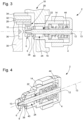
- the Figure 4 shows the control device 2 in perspective and cut longitudinally in said third state, as in Figure 3 .
- the support of the key, with a non-zero pressure, against the transverse/radial surface of the support 14 is obtained by the spring 44 via the washer 38 positioned between the control member 6 and the key and which presses against the latter.
- the spring 44 therefore has a dual function, namely to allow a pusher function for the control device and to maintain the movable part in rotation in a functional and optimal position of the control member, in particular of the magnet. 8, in the absence of an axial pressure exerted on the gripping member 4.
- the key 40 can be mounted on the rotatable part, so as to be able to be placed opposite a radial surface of the support where the cavity 24 opens and surrounding this cavity, and the control device comprises a spring 44 acting on the rotatable part so as to exert thereon an axial force which makes it possible to maintain the key in pressure against the radial surface in the absence of an actuating force, in the opposite direction to the axial force, exerted on the mobile part in rotation and thus to ensure an optimal functional axial position for the control member 6.
- the key therefore prevents the control member 6 can again be introduced into the cavity 24 without removing this key, which is a removable element which is mounted transversely on the rotating part between the control member and the cavity 24 of the support 14 .
- the key is replaced by a movable element, in particular sliding, which is arranged inside the watch case so as to be able, in a first position or configuration, block or limit an axial movement of the movable part in rotation and thus prevent at least a major part of the control member from being able to be introduced into the cavity 24 without a displacement of the movable element in a second position or configuration in which the rotatable part is released and can then be introduced at least for the most part into the cavity.
- a movable element in particular sliding, which is arranged inside the watch case so as to be able, in a first position or configuration, block or limit an axial movement of the movable part in rotation and thus prevent at least a major part of the control member from being able to be introduced into the cavity 24 without a displacement of the movable element in a second position or configuration in which the rotatable part is released and can then be introduced at least for the most part into the cavity.
- the control device comprises an elastic element, secured to the rotatable part or to the support, which is arranged so as to be able to be elastically deformed during an introduction of at least a major part of the control member in the cavity or during an exit of said at least a major part of the control member from the cavity, so as to allow, after an exit of said at least a major part of the control out of the cavity following the introduction of the latter into the cavity or during the exit of said at least a major part of the control member from the cavity, blocking or limitation of the axial movement of the part mobile in rotation preventing said at least a major part of the control member from being able to be introduced again into the cavity without specific intervention to elastically constrain the elastically deformable element again.
Landscapes
- Physics & Mathematics (AREA)
- General Physics & Mathematics (AREA)
- Electric Clocks (AREA)
Abstract
Description
- L'invention concerne le domaine des dispositifs de commande destinés à être montés dans une ouverture traversante usinée dans une carrure d'une boîte de montre et comprenant une partie mobile en rotation ainsi qu'un support de cette partie mobile en rotation, la partie mobile en rotation comprenant un organe de préhension, un organe de commande d'un capteur de rotation ou d'un mécanisme prévu à l'intérieur de la boîte de montre, et une tige reliant l'organe de préhension et l'organe de commande.
- Le document
US 11,042,122 - Le même problème intervient dans le cas d'un capteur de rotation dont le détecteur est prévu dans une région périphérique radiale de l'organe de commande et qui se trouve de l'autre côté de cet organe de commande relativement à l'ouverture prévue dans la boîte de montre pour l'introduction de ce détecteur, lequel est généralement solidaire du mouvement horloger ou d'un module électronique superposé à un tel mouvement horloger. Dans un tel cas, l'organe de commande ne peut être monté sur la tige que suite à l'introduction du détecteur dans la boîte de montre, et donc généralement du mouvement horloger. Ceci pose un problème car l'organe de commande du détecteur de rotation, notamment un détecteur magnétique comprenant un aimant à aimantation radiale formant l'organe de commande, ne peut pas être monté sur la tige du dispositif de commande préalablement au montage du détecteur dans la boîte de montre et donc en général au montage du mouvement horloger dans cette boîte de montre.
- Pour solutionner le problème technique mentionné dans l'arrière-plan technologique, tout en permettant d'occuper efficacement le volume disponible à l'intérieur de la boîte de montre, en particulier sensiblement l'entier des dimensions horizontales intérieures de cette boîte de montre, par le mouvement horloger et éventuellement un module électronique superposé à ce mouvement horloger et/ou un cercle d'encageage, la présente invention concerne un dispositif de commande destiné à être monté dans une ouverture traversante usinée dans une carrure d'une boîte de montre et comprenant une partie mobile en rotation et un support de cette partie mobile en rotation. La partie mobile en rotation comprend un organe de préhension, un organe de commande, formant un capteur de rotation ou prévu pour entraîner un mécanisme situé à l'intérieur de la boîte de montre, et une tige reliant l'organe de préhension et l'organe de commande. Le capteur de rotation et le mécanisme comprennent respectivement un détecteur et un élément de couplage à l'organe de commande qui sont prévus à l'intérieur de la boîte de montre dans une région périphérique radiale de l'organe de commande. Le support a une ouverture circulaire qui est traversée par la tige et qui présente un diamètre inférieur à la dimension radiale maximale de l'organe de commande et à la dimension radiale maximale de l'organe de préhension. Ensuite, le support présente, d'un premier côté de l'ouverture circulaire, une cavité ouverte dans la direction de l'axe de rotation et destinée à déboucher à l'intérieur de la boîte de montre, les dimensions de la cavité étant prévues pour pouvoir y loger au moins une majeure partie de l'organe de commande monté fixement sur la tige, de sorte à pouvoir escamoter momentanément, au moins en majeure partie, cet organe de commande dans la cavité suite à un déplacement axial de la tige dans une position de montage du détecteur ou de l'élément de couplage dans la boîte de montre.
- Dans un mode de réalisation principal, au moins une majeure partie de la portion du support définissant la cavité est prévue à l'intérieur de l'ouverture traversante usinée dans la carrure.
- Dans une variante préférée, la cavité et la partie mobile en rotation sont agencées de manière qu'une partie d'extrémité intérieure de la partie mobile en rotation, comprenant l'organe de commande et située du côté de la cavité relativement à l'ouverture circulaire du support, peut être logée entièrement dans la cavité.
- Dans une variante particulière, le dispositif de commande comprend un élément amovible ou un élément déplaçable qui est agencé pour pouvoir bloquer ou limiter un mouvement axial de la partie mobile en rotation et ainsi empêcher ladite au moins une majeure partie de l'organe de commande de pouvoir être introduite dans la cavité sans un retrait de l'élément amovible ou un déplacement de l'élément déplaçable libérant la partie mobile en rotation.
- D'autres variantes particulières sont décrites par la suite.
- L'invention sera décrite ci-après de manière plus détaillée à l'aide des dessins annexés, donnés à titre d'exemples nullement limitatifs, dans lesquels :
- la
Figure 1 représente, en coupe, un mode de réalisation d'un dispositif de commande d'une montre selon l"Invention avant le montage d'un mouvement et d'un détecteur, associé au dispositif de commande, dans la boîte de montre ; - la
Figure 2 montre le dispositif de commande de laFigure 1 dans un état prévu lors du montage du mouvement et du détecteur dans la boîte de montre ; - la
Figure 3 montre le dispositif de commande de laFigure 1 dans un état fonctionnel après le montage du mouvement et du détecteur dans la boîte de montre ; et - la
Figure 4 est une vue en perspective du dispositif de commande, coupé longitudinalement, dans l'état fonctionnel. - En référence aux Figures jointes on décrira ci-après un mode de réalisation d'un dispositif de commande horloger selon un mode de réalisation de l'invention.
- Le dispositif de commande 2 comprend une partie mobile en rotation qui est formée d'un organe de préhension 4, d'un organe de commande 6 d'un capteur de rotation, lequel est prévu à l'intérieur d'une boîte de montre 18, et d'une tige 12 reliant l'organe de préhension et l'organe de commande. Le dispositif de commande comprend en outre un support 14 de la partie mobile en rotation, ce support étant dimensionné pour pouvoir être introduit à force ou collé dans une ouverture traversante 20 usinée dans une carrure 16 de la boîte de montre. Le support 14 comprend une ouverture circulaire 22 qui est traversée par la tige 12 et qui présente un diamètre inférieur à la dimension radiale maximale D de l'organe de commande 6 et inférieur à la dimension radiale maximale de l'organe de préhension 4.
- L'organe de commande 6 comprend un aimant 8 ayant une aimantation radiale relativement à l'axe de rotation 13 de l'organe mobile en rotation. Cet aimant est agencé sur une partie cylindrique 10 fixée à une extrémité intérieure de la tige 12, cette partie cylindrique formant avec l'aimant 8 et une rondelle 38 une partie d'extrémité intérieure de la partie mobile en rotation. De préférence, l'aimant 8 est un aimant multipolaire. Le terme 'intérieur' est utilisé en référence à la boîte de montre sur laquelle il est prévu de monter le dispositif de commande 2. La rondelle 38 sert à former une première surface radiale pour un appui axial, du côté de l'organe de commande 6, pour une clavette amovible 40 une fois en place sur la tige 12. La clavette amovible 40 est prévue pour limiter un déplacement axial de la partie mobile en rotation une fois le mouvement 30 monté dans la boîte de montre 18 avec le détecteur magnétique 26 formant le capteur de rotation. On remarquera que, dans une variante où la partie cylindrique 10 définit elle-même une surface radiale du côté de l'ouverture circulaire 22, la rondelle 38 n'est pas nécessaire et peut être supprimée. La partie d'extrémité intérieure est montée sur l'extrémité intérieure de la tige 12, de manière à être solidaire en rotation de cette tige, par vissage grâce à des filetages complémentaires prévus sur l'une et l'autre, ou/et par collage, ou par tout autre moyen de fixation approprié pouvant éventuellement utiliser un élément de fixation de la partie d'extrémité intérieure avec la tige.
- Le support présente, du côté intérieur de l'ouverture circulaire 22, une cavité 24 qui est ouverte dans la direction de l'axe de rotation 13 et destinée à déboucher à l'intérieur de la boîte de montre 18. De manière générale, les dimensions de la cavité sont prévues pour pouvoir y loger au moins une majeure partie de l'organe de commande 6 monté sur la tige 12. De préférence, comme montré à la
Figure 2 , la cavité 24 et la partie mobile en rotation sont agencées de manière que ladite partie d'extrémité intérieure de la partie mobile en rotation, qui est située du côté de la cavité relativement à l'ouverture circulaire 22 du support 14, peut être logée quasi entièrement dans la cavité ou, de manière avantageuse, entièrement dans cette cavité. - Comme indiqué, le capteur de rotation comprend un détecteur magnétique 26, lequel est agencé, relativement à l'axe de rotation 13 de la partie mobile en rotation, dans une région périphérique radiale de l'organe de commande, au-dessus de ce dernier. Le détecteur magnétique est agencé fixement dans la boîte de montre à proximité de l'aimant 8 de manière à pouvoir mesurer une variation du champ magnétique généré par cet aimant lorsque ce dernier est entraîné en rotation par un entraînement en rotation de l'organe de préhension.
- Selon une caractéristique très avantageuse de l'invention, au moins une majeure partie de la portion du support 14 définissant la paroi latérale de la cavité 24 est prévue à l'intérieur de l'ouverture traversante 20 usinée dans la carrure 16 une fois ce support monté sur la boîte de montre. Dans une variante préférée permettant de libérer un maximum d'espace à l'intérieur de la boîte de montre et d'avoir le détecteur magnétique 26 situé à proximité de la paroi intérieure de la carrure 16, comme représenté à la
Figure 3 , il est prévu que la portion du support 14 définissant la cavité 24 est presque entièrement située dans l'ouverture traversante 20 de la carrure, ou plus généralement à l'extérieur d'un volume géométrique, ayant une paroi latérale cylindrique, prévu à l'intérieur de la boîte de montre pour le mouvement horloger 30 comprenant le détecteur magnétique 26 ou associé à un module électronique supérieur comprenant ce détecteur magnétique. - A la
Figure 3 , le détecteur magnétique 26 est situé sous un circuit imprimé 28 qui le porte et qui est agencé sous une plaque 32 formant, avec le circuit imprimé et le détecteur magnétique, un module électronique. Dans la variante de laFigure 3 , le module électronique est recouvert par ou comprend un cadran 34 pour un affichage de la montre. Dans la variante montrée à cetteFigure 3 , il est prévu que le dispositif de commande 2 ait deux fonctions, à savoir une première fonction associée à une détection magnétique d'une rotation de la partie mobile en rotation, en particulier de l'organe de préhension 4, par l'intermédiaire du capteur magnétique, constitué du détecteur magnétique 26 et de l'aimant multipolaire 8 de l'organe de commande 6 qui sont situés radialement l'un en face de l'autre, et une deuxième fonction de poussoir. La fonction de poussoir est effectuée par un déplacement axial de la partie mobile en rotation en direction du mouvement horloger qui porte un détecteur de force 36 agencé pour pouvoir détecter une force exercée sur lui par l'extrémité de la tige 12 ou plus généralement par la partie d'extrémité intérieure de la partie mobile en rotation. Un ressort 44 est prévu dans le dispositif de commande 2 pour exercer une force de rappel sur la partie mobile en rotation, en particulier sur l'organe de préhension 4, de manière à permettre la fonction de poussoir et en plus permettre de ramener l'organe de commande 6, en particulier l'aimant multipolaire 8, dans une position axiale qui soit la meilleure pour le fonctionnement du capteur magnétique de rotation. - Selon l'invention, l'agencement du dispositif de commande permet de déplacer axialement la partie d'extrémité intérieure de la partie mobile en rotation, et donc l'organe de commande, une fois cette partie d'extrémité intérieure montée sur la tige de manière à être solidaire en rotation avec celle-ci et à être maintenu dans une position axiale fixe relativement à cette tige, pour mettre cette partie d'extrémité intérieure en retrait de sa position fonctionnelle, à savoir pour la placer dans une position axiale de montage du détecteur magnétique, et plus généralement d'un mouvement ou d'un module comprenant ce détecteur magnétique, dans la boîte de montre. Cette position axiale de montage correspond à une position axiale tirée de la tige et donc de l'organe de préhension s'il est déjà avantageusement monté fixement sur cette tige lors du montage du détecteur magnétique dans la boîte de montre. On notera que le montage du détecteur magnétique dans la boîte de montre est prévu avant de mettre en place sur la tige, dans une étape finale, un élément amovible ou déplaçable pour bloquer ou limiter un déplacement axial de la partie mobile en rotation et empêcher que la partie d'extrémité intérieure puisse se déplacer vers la position axiale de montage. A cet effet, il est prévu que l'élément amovible ou déplaçable, en particulier une clavette 40, soit placé entre l'organe de commande 6 et une deuxième surface radiale, formée par le support 14, prévue pour un appui axial, du côté de l'ouverture traversante 20 dans la carrure 16, pour cet élément amovible ou déplaçable une fois en place. On remarquera que, dans une variante non représentée, la deuxième surface radiale peut être formée par une surface intérieure de la carrure 16.
- Grâce aux caractéristiques du dispositif de commande selon l'invention, il est possible d'escamoter momentanément, au moins en majeure partie, l'organe de commande et plus généralement la partie d'extrémité intérieure de la partie mobile en rotation dans la cavité intérieure du support par un déplacement axial momentané de l'organe de commande, et plus généralement de la partie mobile en rotation, dans une position de montage du détecteur dans la boîte de montre. Plus particulièrement, l'invention permet de retirer momentanément l'organe de commande, déjà monté fixement sur la tige, en le logeant au moins en partie et de préférence entièrement à l'intérieur de l'ouverture traversante usinée dans la carrure pour le passage et la fixation du dispositif de commande.
- A la
Figure 1 , le dispositif de commande 2 est représenté monté dans une ouverture 20 d'une boîte de montre 18 et dans un premier état pour lequel le ressort 44 est détendu. Comme indiqué, le ressort 44 est prévu pour exercer, lorsque le dispositif de commande est dans un état fonctionnel, une force axiale vers l'extérieur sur l'organe de préhension 4 et ainsi sur la partie mobile en rotation. Dans le premier état, l'organe de commande 6 et plus généralement la partie d'extrémité intérieure de la partie mobile en rotation sont situés partiellement dans la cavité 24. On remarquera que la portion du support définissant la paroi latérale de la cavité 24 est située presque entièrement, et donc en majeure partie, dans l'ouverture traversante 20 prévue dans la carrure 16 pour le passage du dispositif de commande 2. Ce premier état du dispositif de commande est prévu avant le montage dans la boîte de montre du mouvement et en particulier du module électronique supérieur comprenant le détecteur magnétique 26. C'est un état avantageux pour la livraison de la boîte de montre à une manufacture horlogère. En effet, on observe que le dispositif de commande est presque complètement monté, seul l'élément 40 de limitation du déplacement axial de la partie mobile en rotation n'étant pas encore montée de manière amovible sur la tige 12. En particulier, dans ce premier état, l'organe de commande 6 et l'organe de préhension sont déjà montés fixement sur la tige 12, ce qui est avantageux puisque le fabricant de la boîte de montre peut ainsi livrer cette boîte de montre avec un dispositif de commande dont les principaux éléments sont déjà assemblés. - A la
Figure 2 , la partie mobile en rotation est placée dans une position axiale de montage du mouvement 30, du module électronique supérieur (références 26, 28, 32) et du cadran 34. Dans cette position axiale de montage, correspondant à un deuxième état de la partie mobile en rotation, l'organe de commande 6 est entièrement introduit dans la cavité 24 et est ainsi en majeure partie situé à l'intérieur de l'ouverture 20 usinée dans la carrure 16. Dans cette position en retrait où la partie mobile en rotation est retirée et l'organe de commande 6 escamoté dans la cavité 24 et plus spécifiquement placé momentanément en majeure partie dans l'ouverture traversante 20, il est alors possible d'introduire depuis le fond de la boîte de montre le mouvement horloger 30 et notamment le module électronique supérieur qui comprend le détecteur magnétique 26, lequel est prévu, en fonctionnement normal, dans une position radiale relativement à l'organe de commande 6 et à un niveau supérieur, c'est-à-dire dans une région périphérique radiale de l'organe de commande qui est située au-dessus de cet organe de commande. Sans les caractéristiques du dispositif de commande selon l'invention, une telle introduction du détecteur magnétique par le fond de la boîte de montre ne pourrait être effectuée si l'organe de commande 6 est déjà monté sur la tige 12 et placé directement dans une position fonctionnelle pour le capteur de rotation, étant donné que, dans la variante principale décrite, une introduction du détecteur magnétique est prévue par le fond de la boîte de montre, comme pour le mouvement horloger. - A la
Figure 3 , le mouvement 30 et le module électronique supérieur ont été mis en place dans la boîte de montre et le dispositif de commande 2 est alors mis dans une position axiale fonctionnelle. Dans ce troisième état, le dispositif de commande est dans une configuration finale complètement assemblé et la partie mobile en rotation est fonctionnelle. Ce troisième état est assuré par une clavette 40 qui est montée de manière amovible sur la tige 12 et plus généralement sur la partie mobile en rotation pour limiter le déplacement axial de la partie mobile en rotation et surtout assurer un positionnement axial fonctionnel à l'organe de commande, notamment pour le capteur de rotation. La clavette, qui est un élément de limitation du mouvement axial de la partie mobile en rotation, est prévue amovible et n'engendre aucune difficulté pour son montage sur la tige 12 par une introduction transversale, c'est-à-dire radiale relativement à l'axe de rotation 13, depuis le fond de la boîte de montre suite au montage du mouvement 30 et du capteur magnétique 26. - On remarquera que, contrairement à une réalisation de l'art antérieur décrite précédemment, la clavette 40 est agencée en amont de l'organe de commande 6, c'est-à-dire qu'elle est située entre cet organe de commande et la cavité 24 ou plus généralement la paroi intérieure de la carrure 16 et en particulier l'ouverture traversante 20 dans cette carrure. Ainsi, la clavette peut venir en appui axial contre une partie fixe de la boîte de montre ou avantageusement du support 14, alors que l'organe de commande est situé en aval, c'est-à-dire du côté intérieur de cette clavette, et peut donc interagir radialement avec un élément placé à l'intérieur de la boîte de montre. Dans la variante avantageuse représentée à la
Figure 3 , la clavette, une fois mise en place, est en appui axial contre une surface transversale / radiale du support 14 située à l'extrémité intérieure de la cavité 24. LaFigure 4 montre le dispositif de commande 2 en perspective et coupé longitudinalement dans ledit troisième état, comme à laFigure 3 . - L'appui de la clavette, avec une pression non nulle, contre la surface transversale / radiale du support 14 est obtenu par le ressort 44 via la rondelle 38 positionnée entre l'organe de commande 6 et la clavette et qui appuie contre cette dernière. Le ressort 44 a donc une double fonction, à savoir de permettre une fonction de poussoir pour le dispositif de commande et un maintien de la partie mobile en rotation dans une position fonctionnelle et optimale de l'organe de commande, en particulier de l'aimant 8, en l'absence d'une pression axiale exercée sur l'organe de préhension 4. En résumé, la clavette 40 peut être montée sur la partie mobile en rotation, de manière à pouvoir se placer en face d'une surface radiale du support où débouche la cavité 24 et entourant cette cavité, et le dispositif de commande comprend un ressort 44 agissant sur la partie mobile en rotation de manière à exercer sur celle-ci une force axiale qui permet de maintenir la clavette en pression contre la surface radiale en l'absence d'une force d'actionnement, de sens opposé à la force axiale, exercée sur la partie mobile en rotation et ainsi d'assurer une position axiale fonctionnelle optimale pour l'organe de commande 6. La clavette empêche donc que l'organe de commande 6 puisse à nouveau être introduit dans la cavité 24 sans un retrait de cette clavette, laquelle est un élément amovible qui se monte transversalement sur la partie mobile en rotation entre l'organe de commande et la cavité 24 du support 14.
- En relation avec la limitation du déplacement axial de la partie mobile en rotation ou le blocage axial de cette dernière, deux variantes non représentées sont décrites ci-après. Dans une première variante, la clavette est remplacée par un élément déplaçable, en particulier coulissant, qui est agencé à l'intérieur de la boîte de montre de manière à pouvoir, dans une première position ou configuration, bloquer ou limiter un mouvement axial de la partie mobile en rotation et ainsi empêcher qu'au moins une majeure partie de l'organe de commande puisse être introduit dans la cavité 24 sans un déplacement de l'élément déplaçable dans une seconde position ou configuration dans laquelle la partie mobile en rotation est libérée et peut alors être introduite au moins en majeure partie dans la cavité.
- Dans une deuxième variante, le dispositif de commande comprend un élément élastique, solidaire de la partie mobile en rotation ou du support, qui est agencé de manière à pouvoir être élastiquement déformé lors d'une introduction d'au moins une majeure partie de l'organe de commande dans la cavité ou lors d'une sortie de ladite au moins une majeure partie de l'organe de commande hors de la cavité, de sorte à permettre, après une sortie de ladite au moins une majeure partie de l'organe de commande hors de la cavité suivant l'introduction de celle-ci dans la cavité ou lors de la sortie de ladite au moins une majeure partie de l'organe de commande hors de la cavité, un blocage ou une limitation du mouvement axial de la partie mobile en rotation empêchant à ladite au moins une majeure partie de l'organe de commande de pouvoir à nouveau être introduite dans la cavité sans une intervention spécifique pour contraindre élastiquement à nouveau l'élément élastiquement déformable.
Claims (8)
- Dispositif de commande (2) destiné à être monté dans une ouverture traversante (20) usinée dans une carrure (16) d'une boîte de montre (18) et comprenant une partie mobile en rotation et un support (14) de cette partie mobile en rotation, la partie mobile en rotation comprenant un organe de préhension (4), un organe de commande (6), formant un capteur de rotation (26) ou prévu pour entraîner un mécanisme situé à l'intérieur de la boîte de montre, et une tige (12) reliant l'organe de préhension et l'organe de commande, le capteur de rotation et le mécanisme comprenant respectivement un détecteur et un élément de couplage à l'organe de commande qui sont prévus à l'intérieur de la boîte de montre dans une région périphérique radiale de l'organe de commande, le support (14) ayant une ouverture circulaire (22) qui est traversée par la tige et qui présente un diamètre inférieur à la dimension radiale maximale (D) de l'organe de commande et à la dimension radiale maximale de l'organe de préhension ; caractérisé en ce que le support présente, d'un premier côté de l'ouverture circulaire, une cavité (24) ouverte dans la direction de l'axe de rotation et destinée à déboucher à l'intérieur de la boîte de montre, les dimensions de la cavité étant prévues pour pouvoir y loger au moins une majeure partie de l'organe de commande monté fixement sur la tige, de sorte à pouvoir escamoter momentanément, au moins en majeure partie, cet organe de commande dans la cavité suite à un déplacement axial de la tige dans une position de montage du détecteur ou de l'élément de couplage dans la boîte de montre.
- Dispositif de commande selon la revendication 1, caractérisé en ce qu'au moins une majeure partie de la portion du support (14) définissant une paroi latérale de la cavité (24) est prévue à l'intérieur de l'ouverture traversante (20) usinée dans la carrure.
- Dispositif de commande selon la revendication 2, caractérisé en ce que la cavité (24) et la partie mobile en rotation sont agencées de manière qu'une partie d'extrémité intérieure de la partie mobile en rotation, comprenant l'organe de commande (6) et située du côté de la cavité relativement à l'ouverture circulaire (22) du support (14), peut être logée entièrement dans la cavité.
- Dispositif de commande selon une quelconque des revendications précédentes, caractérisé en ce qu'il comprend un élément amovible (40) ou un élément déplaçable qui est agencé pour pouvoir bloquer ou limiter un mouvement axial de la partie mobile en rotation et ainsi empêcher ladite au moins une majeure partie de l'organe de commande de pouvoir être introduite dans la cavité (24) sans un retrait de l'élément amovible ou un déplacement de l'élément déplaçable libérant la partie mobile en rotation.
- Dispositif de commande selon la revendication 4, caractérisé en ce que l'élément amovible (40) est une clavette qui peut être montée sur la partie mobile en rotation de manière à pouvoir se placer en face d'une surface radiale du support (14) où débouche la cavité et entourant cette cavité ; et en ce que le dispositif de commande comprend en outre un ressort (44) agissant sur la partie mobile en rotation de manière à exercer sur celle-ci une force axiale qui permet de maintenir la clavette en pression contre ladite surface radiale en l'absence d'une force d'actionnement, de sens opposé à la force axiale, exercée sur la partie mobile en rotation.
- Dispositif de commande selon une quelconque des revendications 1 à 3, caractérisé en ce qu'il comprend un élément élastique, solidaire de la partie mobile en rotation ou du support, qui est agencé de manière à pouvoir être élastiquement déformé lors d'une introduction de ladite au moins une majeure partie de l'organe de commande dans la cavité ou lors d'une sortie de ladite au moins une majeure partie de l'organe de commande hors de la cavité, de sorte à permettre, après une sortie de ladite au moins une majeure partie de l'organe de commande hors de la cavité suivant ladite introduction de celle-ci dans la cavité ou lors de ladite sortie de ladite au moins une majeure partie de l'organe de commande hors de la cavité, un blocage ou une limitation du mouvement axial de la partie mobile en rotation empêchant à ladite au moins une majeure partie de l'organe de commande de pouvoir à nouveau être introduite dans la cavité sans une intervention spécifique pour contraindre élastiquement à nouveau l'élément élastiquement déformable.
- Dispositif de commande selon une quelconque des revendications précédentes, caractérisé en ce que l'organe de commande (6) comprend un aimant (8) à aimantation radiale relativement à l'axe de rotation (13) ; et en ce que le détecteur (26) est un détecteur magnétique agencé fixement dans la boîte de montre à proximité de l'aimant de manière à pouvoir mesurer une variation du champ magnétique généré par cet aimant lorsque ce dernier est entraîné en rotation par un entraînement en rotation de l'organe de préhension.
- Montre comprenant un dispositif de commande et une boîte de montre (18) formée par une carrure (16) dans laquelle est usinée une ouverture traversante (20) pour le passage du dispositif de commande, lequel est monté sur la boîte de montre et permet à un utilisateur de commander au moins une fonction de la montre ; caractérisée en ce que le dispositif de commande est agencé selon une quelconque des revendications précédentes.
Priority Applications (7)
| Application Number | Priority Date | Filing Date | Title |
|---|---|---|---|
| EP22158028.5A EP4231100B1 (fr) | 2022-02-22 | 2022-02-22 | Dispositif de commande horloger |
| FIEP22158028.5T FI4231100T3 (fi) | 2022-02-22 | 2022-02-22 | Kellon ohjauslaite |
| US18/155,508 US12393163B2 (en) | 2022-02-22 | 2023-01-17 | Horological control device |
| JP2023015875A JP7496905B2 (ja) | 2022-02-22 | 2023-02-06 | 計時器用制御デバイス |
| KR1020230017489A KR102816159B1 (ko) | 2022-02-22 | 2023-02-09 | 측시 제어 디바이스 |
| CN202320292012.0U CN220064635U (zh) | 2022-02-22 | 2023-02-22 | 钟表的控制装置和包括此类控制装置的表 |
| CN202310152605.1A CN116643476B (zh) | 2022-02-22 | 2023-02-22 | 钟表控制装置 |
Applications Claiming Priority (1)
| Application Number | Priority Date | Filing Date | Title |
|---|---|---|---|
| EP22158028.5A EP4231100B1 (fr) | 2022-02-22 | 2022-02-22 | Dispositif de commande horloger |
Publications (2)
| Publication Number | Publication Date |
|---|---|
| EP4231100A1 true EP4231100A1 (fr) | 2023-08-23 |
| EP4231100B1 EP4231100B1 (fr) | 2024-09-18 |
Family
ID=80447105
Family Applications (1)
| Application Number | Title | Priority Date | Filing Date |
|---|---|---|---|
| EP22158028.5A Active EP4231100B1 (fr) | 2022-02-22 | 2022-02-22 | Dispositif de commande horloger |
Country Status (6)
| Country | Link |
|---|---|
| US (1) | US12393163B2 (fr) |
| EP (1) | EP4231100B1 (fr) |
| JP (1) | JP7496905B2 (fr) |
| KR (1) | KR102816159B1 (fr) |
| CN (2) | CN220064635U (fr) |
| FI (1) | FI4231100T3 (fr) |
Families Citing this family (2)
| Publication number | Priority date | Publication date | Assignee | Title |
|---|---|---|---|---|
| FI4231100T3 (fi) * | 2022-02-22 | 2024-11-29 | Eta Sa Mft Horlogere Suisse | Kellon ohjauslaite |
| CN121634771A (zh) * | 2024-08-23 | 2026-03-10 | 荣耀终端股份有限公司 | 可穿戴设备 |
Citations (3)
| Publication number | Priority date | Publication date | Assignee | Title |
|---|---|---|---|---|
| KR20160070999A (ko) * | 2014-12-11 | 2016-06-21 | 엘지전자 주식회사 | 이동 단말기 |
| EP3650961A1 (fr) * | 2013-06-11 | 2020-05-13 | Apple Inc. | Montre électronique dotée d'un mécanisme de contrôle rotatif |
| US11042122B2 (en) | 2018-03-06 | 2021-06-22 | Seiko Instruments Inc. | Timepiece with rotatable crown having tactile feel |
Family Cites Families (14)
| Publication number | Priority date | Publication date | Assignee | Title |
|---|---|---|---|---|
| KR19990088020A (ko) * | 1998-05-13 | 1999-12-27 | 에따 쏘시에떼 아노님 파브리끄 데보슈 | 시계,특히크로노그래프의누름단추 |
| DE602006019749D1 (de) * | 2006-11-09 | 2011-03-03 | Swatch Group Res & Dev Ltd | Magnetische Vorrichtung zur Betätigung einer Uhr |
| FI124328B (fi) * | 2008-12-31 | 2014-06-30 | Suunto Oy | Kaksitoiminen säätöelin rannetietokoneelle tai vastaavalle ja menetelmä rannetietokoneen tai vastaavan päätelaitteen säätämiseksi |
| JP5861908B2 (ja) | 2011-07-22 | 2016-02-16 | カシオ計算機株式会社 | スイッチ装置 |
| CH708356A1 (fr) * | 2013-07-17 | 2015-01-30 | Société Anonyme De La Manufacture D Horlogerie Audemars Piguet & Cie | Dispositif de commande pour pièce d'horlogerie. |
| JP6345782B2 (ja) | 2013-08-09 | 2018-06-20 | アップル インコーポレイテッド | 電子デバイス用のタクタイルスイッチ |
| WO2016144919A1 (fr) * | 2015-03-08 | 2016-09-15 | Apple Inc. | Joint d'étanchéité compressible pour mécanismes d'entrée à rotation et translation |
| US10222755B2 (en) * | 2015-04-21 | 2019-03-05 | Motorola Mobility Llc | Device with axial lock and retention device and methods therefor |
| JP6829116B2 (ja) * | 2017-03-13 | 2021-02-10 | セイコーインスツル株式会社 | りゅうずロック機構付き時計 |
| CH713588B1 (fr) * | 2017-03-18 | 2020-12-15 | Red & White Intellectual Property Man Sa | Mécanisme musical pour mouvement horloger. |
| US10725429B2 (en) * | 2017-05-24 | 2020-07-28 | Omega Sa | Timepiece containing a locking device for a pusher |
| CN209560398U (zh) * | 2018-08-24 | 2019-10-29 | 苹果公司 | 电子表 |
| EP3835885B1 (fr) * | 2019-12-10 | 2023-12-06 | The Swatch Group Research and Development Ltd | Montre pourvue d'un organe de commande |
| FI4231100T3 (fi) * | 2022-02-22 | 2024-11-29 | Eta Sa Mft Horlogere Suisse | Kellon ohjauslaite |
-
2022
- 2022-02-22 FI FIEP22158028.5T patent/FI4231100T3/fi active
- 2022-02-22 EP EP22158028.5A patent/EP4231100B1/fr active Active
-
2023
- 2023-01-17 US US18/155,508 patent/US12393163B2/en active Active
- 2023-02-06 JP JP2023015875A patent/JP7496905B2/ja active Active
- 2023-02-09 KR KR1020230017489A patent/KR102816159B1/ko active Active
- 2023-02-22 CN CN202320292012.0U patent/CN220064635U/zh not_active Withdrawn - After Issue
- 2023-02-22 CN CN202310152605.1A patent/CN116643476B/zh active Active
Patent Citations (3)
| Publication number | Priority date | Publication date | Assignee | Title |
|---|---|---|---|---|
| EP3650961A1 (fr) * | 2013-06-11 | 2020-05-13 | Apple Inc. | Montre électronique dotée d'un mécanisme de contrôle rotatif |
| KR20160070999A (ko) * | 2014-12-11 | 2016-06-21 | 엘지전자 주식회사 | 이동 단말기 |
| US11042122B2 (en) | 2018-03-06 | 2021-06-22 | Seiko Instruments Inc. | Timepiece with rotatable crown having tactile feel |
Also Published As
| Publication number | Publication date |
|---|---|
| CN116643476B (zh) | 2026-02-17 |
| US12393163B2 (en) | 2025-08-19 |
| CN220064635U (zh) | 2023-11-21 |
| FI4231100T3 (fi) | 2024-11-29 |
| EP4231100B1 (fr) | 2024-09-18 |
| KR102816159B1 (ko) | 2025-06-02 |
| US20230266713A1 (en) | 2023-08-24 |
| KR20230126192A (ko) | 2023-08-29 |
| JP2023122550A (ja) | 2023-09-01 |
| JP7496905B2 (ja) | 2024-06-07 |
| CN116643476A (zh) | 2023-08-25 |
Similar Documents
| Publication | Publication Date | Title |
|---|---|---|
| EP4231100B1 (fr) | Dispositif de commande horloger | |
| EP0655664A1 (fr) | Couronne-poussoir pour pièce d'horlogerie | |
| WO2005038538A1 (fr) | Dispositif de commande a couronne-poussoir pour montre | |
| CH705043A2 (fr) | Pièce d'horlogerie portable incluant un bouton-poussoir. | |
| WO2011104480A1 (fr) | Couronne de remontoir de montre multifonctions | |
| CH703455A1 (fr) | Couronne et procede d'activation d'une telle couronne sur une boîte de montre. | |
| EP2182417A2 (fr) | Couronne à visser et procédé d'orientation d'une telle couronne sur une boîte de montre | |
| CH704250A2 (fr) | Mécanisme de transmission de mouvements axiaux et rotatifs entre deux axes décalés et pièce d'horlogerie comportant un tel mécanisme. | |
| CH714613A2 (fr) | Mouvement et pièce d'horlogerie. | |
| EP4047423A1 (fr) | Montre munie d'un dispositif de verrouillage d'un organe de commande extérieur | |
| EP3835887A1 (fr) | Montre pourvue d'un organe de commande | |
| CH719445A2 (fr) | Dispositif de commande horloger. | |
| EP4086710A1 (fr) | Boite de montre comprenant un mécanisme d'actionnement d'un indicateur mobile | |
| FR2934904A1 (fr) | Unite de reglage pour cadran d'horloge, montre munie de l'unite de reglage et son procede de reglage. | |
| FR2969324A1 (fr) | Montre-bracelet equipee d'une capsule aneroide. | |
| EP2010972A2 (fr) | Piece d'horlogerie comportant un mecanisme de mise a l'heure commande par une lunette tournante | |
| EP1923754A1 (fr) | Mouvement d'horlogerie équipé d'un module d'affichage | |
| EP1960848B1 (fr) | Marteau pour piece d'horlogerie | |
| EP4092490A1 (fr) | Dispositif de commande d'un mouvement horloger avec retour tactile et pièce d'horlogerie, notamment montre, comprenant un tel dispositif | |
| EP3239785B1 (fr) | Dispositif de maintien d'un mobile | |
| CH721235A2 (fr) | Dispositif de commande pour montre | |
| EP4546054A1 (fr) | Dispositif de commande pour montre | |
| EP4546055A1 (fr) | Dispositif d'embrayage d'un système de commande d'un mouvement horloger | |
| EP4575657A1 (fr) | Dispositif de mise à l'heure d'un mouvement horloger | |
| CH720284B1 (fr) | Dispositif de commande d'une pièce d'horlogerie. |
Legal Events
| Date | Code | Title | Description |
|---|---|---|---|
| PUAI | Public reference made under article 153(3) epc to a published international application that has entered the european phase |
Free format text: ORIGINAL CODE: 0009012 |
|
| STAA | Information on the status of an ep patent application or granted ep patent |
Free format text: STATUS: THE APPLICATION HAS BEEN PUBLISHED |
|
| AK | Designated contracting states |
Kind code of ref document: A1 Designated state(s): AL AT BE BG CH CY CZ DE DK EE ES FI FR GB GR HR HU IE IS IT LI LT LU LV MC MK MT NL NO PL PT RO RS SE SI SK SM TR |
|
| P01 | Opt-out of the competence of the unified patent court (upc) registered |
Effective date: 20231109 |
|
| STAA | Information on the status of an ep patent application or granted ep patent |
Free format text: STATUS: REQUEST FOR EXAMINATION WAS MADE |
|
| 17P | Request for examination filed |
Effective date: 20240223 |
|
| RBV | Designated contracting states (corrected) |
Designated state(s): AL AT BE BG CH CY CZ DE DK EE ES FI FR GB GR HR HU IE IS IT LI LT LU LV MC MK MT NL NO PL PT RO RS SE SI SK SM TR |
|
| GRAP | Despatch of communication of intention to grant a patent |
Free format text: ORIGINAL CODE: EPIDOSNIGR1 |
|
| STAA | Information on the status of an ep patent application or granted ep patent |
Free format text: STATUS: GRANT OF PATENT IS INTENDED |
|
| RIC1 | Information provided on ipc code assigned before grant |
Ipc: G04G 21/02 20100101ALI20240610BHEP Ipc: G04C 3/00 20060101ALI20240610BHEP Ipc: G04G 17/02 20060101ALI20240610BHEP Ipc: G04B 37/06 20060101ALI20240610BHEP Ipc: G04B 3/04 20060101AFI20240610BHEP |
|
| INTG | Intention to grant announced |
Effective date: 20240627 |
|
| GRAS | Grant fee paid |
Free format text: ORIGINAL CODE: EPIDOSNIGR3 |
|
| GRAA | (expected) grant |
Free format text: ORIGINAL CODE: 0009210 |
|
| STAA | Information on the status of an ep patent application or granted ep patent |
Free format text: STATUS: THE PATENT HAS BEEN GRANTED |
|
| AK | Designated contracting states |
Kind code of ref document: B1 Designated state(s): AL AT BE BG CH CY CZ DE DK EE ES FI FR GB GR HR HU IE IS IT LI LT LU LV MC MK MT NL NO PL PT RO RS SE SI SK SM TR |
|
| REG | Reference to a national code |
Ref country code: GB Ref legal event code: FG4D Free format text: NOT ENGLISH |
|
| REG | Reference to a national code |
Ref country code: CH Ref legal event code: EP |
|
| REG | Reference to a national code |
Ref country code: DE Ref legal event code: R096 Ref document number: 602022006106 Country of ref document: DE |
|
| REG | Reference to a national code |
Ref country code: IE Ref legal event code: FG4D Free format text: LANGUAGE OF EP DOCUMENT: FRENCH |
|
| REG | Reference to a national code |
Ref country code: FI Ref legal event code: FGE |
|
| REG | Reference to a national code |
Ref country code: LT Ref legal event code: MG9D |
|
| PG25 | Lapsed in a contracting state [announced via postgrant information from national office to epo] |
Ref country code: NO Free format text: LAPSE BECAUSE OF FAILURE TO SUBMIT A TRANSLATION OF THE DESCRIPTION OR TO PAY THE FEE WITHIN THE PRESCRIBED TIME-LIMIT Effective date: 20241218 |
|
| PG25 | Lapsed in a contracting state [announced via postgrant information from national office to epo] |
Ref country code: GR Free format text: LAPSE BECAUSE OF FAILURE TO SUBMIT A TRANSLATION OF THE DESCRIPTION OR TO PAY THE FEE WITHIN THE PRESCRIBED TIME-LIMIT Effective date: 20241219 |
|
| PG25 | Lapsed in a contracting state [announced via postgrant information from national office to epo] |
Ref country code: BG Free format text: LAPSE BECAUSE OF FAILURE TO SUBMIT A TRANSLATION OF THE DESCRIPTION OR TO PAY THE FEE WITHIN THE PRESCRIBED TIME-LIMIT Effective date: 20240918 |
|
| PG25 | Lapsed in a contracting state [announced via postgrant information from national office to epo] |
Ref country code: LV Free format text: LAPSE BECAUSE OF FAILURE TO SUBMIT A TRANSLATION OF THE DESCRIPTION OR TO PAY THE FEE WITHIN THE PRESCRIBED TIME-LIMIT Effective date: 20240918 |
|
| PG25 | Lapsed in a contracting state [announced via postgrant information from national office to epo] |
Ref country code: HR Free format text: LAPSE BECAUSE OF FAILURE TO SUBMIT A TRANSLATION OF THE DESCRIPTION OR TO PAY THE FEE WITHIN THE PRESCRIBED TIME-LIMIT Effective date: 20240918 |
|
| REG | Reference to a national code |
Ref country code: NL Ref legal event code: MP Effective date: 20240918 |
|
| PG25 | Lapsed in a contracting state [announced via postgrant information from national office to epo] |
Ref country code: RS Free format text: LAPSE BECAUSE OF FAILURE TO SUBMIT A TRANSLATION OF THE DESCRIPTION OR TO PAY THE FEE WITHIN THE PRESCRIBED TIME-LIMIT Effective date: 20241218 |
|
| PG25 | Lapsed in a contracting state [announced via postgrant information from national office to epo] |
Ref country code: RS Free format text: LAPSE BECAUSE OF FAILURE TO SUBMIT A TRANSLATION OF THE DESCRIPTION OR TO PAY THE FEE WITHIN THE PRESCRIBED TIME-LIMIT Effective date: 20241218 Ref country code: NO Free format text: LAPSE BECAUSE OF FAILURE TO SUBMIT A TRANSLATION OF THE DESCRIPTION OR TO PAY THE FEE WITHIN THE PRESCRIBED TIME-LIMIT Effective date: 20241218 Ref country code: LV Free format text: LAPSE BECAUSE OF FAILURE TO SUBMIT A TRANSLATION OF THE DESCRIPTION OR TO PAY THE FEE WITHIN THE PRESCRIBED TIME-LIMIT Effective date: 20240918 Ref country code: HR Free format text: LAPSE BECAUSE OF FAILURE TO SUBMIT A TRANSLATION OF THE DESCRIPTION OR TO PAY THE FEE WITHIN THE PRESCRIBED TIME-LIMIT Effective date: 20240918 Ref country code: GR Free format text: LAPSE BECAUSE OF FAILURE TO SUBMIT A TRANSLATION OF THE DESCRIPTION OR TO PAY THE FEE WITHIN THE PRESCRIBED TIME-LIMIT Effective date: 20241219 Ref country code: BG Free format text: LAPSE BECAUSE OF FAILURE TO SUBMIT A TRANSLATION OF THE DESCRIPTION OR TO PAY THE FEE WITHIN THE PRESCRIBED TIME-LIMIT Effective date: 20240918 |
|
| REG | Reference to a national code |
Ref country code: AT Ref legal event code: MK05 Ref document number: 1725200 Country of ref document: AT Kind code of ref document: T Effective date: 20240918 |
|
| PG25 | Lapsed in a contracting state [announced via postgrant information from national office to epo] |
Ref country code: NL Free format text: LAPSE BECAUSE OF FAILURE TO SUBMIT A TRANSLATION OF THE DESCRIPTION OR TO PAY THE FEE WITHIN THE PRESCRIBED TIME-LIMIT Effective date: 20240918 |
|
| PG25 | Lapsed in a contracting state [announced via postgrant information from national office to epo] |
Ref country code: PT Free format text: LAPSE BECAUSE OF FAILURE TO SUBMIT A TRANSLATION OF THE DESCRIPTION OR TO PAY THE FEE WITHIN THE PRESCRIBED TIME-LIMIT Effective date: 20250120 Ref country code: IS Free format text: LAPSE BECAUSE OF FAILURE TO SUBMIT A TRANSLATION OF THE DESCRIPTION OR TO PAY THE FEE WITHIN THE PRESCRIBED TIME-LIMIT Effective date: 20250118 |
|
| PG25 | Lapsed in a contracting state [announced via postgrant information from national office to epo] |
Ref country code: RO Free format text: LAPSE BECAUSE OF FAILURE TO SUBMIT A TRANSLATION OF THE DESCRIPTION OR TO PAY THE FEE WITHIN THE PRESCRIBED TIME-LIMIT Effective date: 20240918 Ref country code: SM Free format text: LAPSE BECAUSE OF FAILURE TO SUBMIT A TRANSLATION OF THE DESCRIPTION OR TO PAY THE FEE WITHIN THE PRESCRIBED TIME-LIMIT Effective date: 20240918 |
|
| PG25 | Lapsed in a contracting state [announced via postgrant information from national office to epo] |
Ref country code: ES Free format text: LAPSE BECAUSE OF FAILURE TO SUBMIT A TRANSLATION OF THE DESCRIPTION OR TO PAY THE FEE WITHIN THE PRESCRIBED TIME-LIMIT Effective date: 20240918 |
|
| PG25 | Lapsed in a contracting state [announced via postgrant information from national office to epo] |
Ref country code: EE Free format text: LAPSE BECAUSE OF FAILURE TO SUBMIT A TRANSLATION OF THE DESCRIPTION OR TO PAY THE FEE WITHIN THE PRESCRIBED TIME-LIMIT Effective date: 20240918 Ref country code: AT Free format text: LAPSE BECAUSE OF FAILURE TO SUBMIT A TRANSLATION OF THE DESCRIPTION OR TO PAY THE FEE WITHIN THE PRESCRIBED TIME-LIMIT Effective date: 20240918 |
|
| PGFP | Annual fee paid to national office [announced via postgrant information from national office to epo] |
Ref country code: CH Payment date: 20250301 Year of fee payment: 4 |
|
| PG25 | Lapsed in a contracting state [announced via postgrant information from national office to epo] |
Ref country code: CZ Free format text: LAPSE BECAUSE OF FAILURE TO SUBMIT A TRANSLATION OF THE DESCRIPTION OR TO PAY THE FEE WITHIN THE PRESCRIBED TIME-LIMIT Effective date: 20240918 Ref country code: PL Free format text: LAPSE BECAUSE OF FAILURE TO SUBMIT A TRANSLATION OF THE DESCRIPTION OR TO PAY THE FEE WITHIN THE PRESCRIBED TIME-LIMIT Effective date: 20240918 |
|
| PG25 | Lapsed in a contracting state [announced via postgrant information from national office to epo] |
Ref country code: IT Free format text: LAPSE BECAUSE OF FAILURE TO SUBMIT A TRANSLATION OF THE DESCRIPTION OR TO PAY THE FEE WITHIN THE PRESCRIBED TIME-LIMIT Effective date: 20240918 Ref country code: SK Free format text: LAPSE BECAUSE OF FAILURE TO SUBMIT A TRANSLATION OF THE DESCRIPTION OR TO PAY THE FEE WITHIN THE PRESCRIBED TIME-LIMIT Effective date: 20240918 |
|
| REG | Reference to a national code |
Ref country code: DE Ref legal event code: R097 Ref document number: 602022006106 Country of ref document: DE |
|
| PG25 | Lapsed in a contracting state [announced via postgrant information from national office to epo] |
Ref country code: DK Free format text: LAPSE BECAUSE OF FAILURE TO SUBMIT A TRANSLATION OF THE DESCRIPTION OR TO PAY THE FEE WITHIN THE PRESCRIBED TIME-LIMIT Effective date: 20240918 |
|
| PLBE | No opposition filed within time limit |
Free format text: ORIGINAL CODE: 0009261 |
|
| STAA | Information on the status of an ep patent application or granted ep patent |
Free format text: STATUS: NO OPPOSITION FILED WITHIN TIME LIMIT |
|
| 26N | No opposition filed |
Effective date: 20250619 |
|
| PG25 | Lapsed in a contracting state [announced via postgrant information from national office to epo] |
Ref country code: SE Free format text: LAPSE BECAUSE OF FAILURE TO SUBMIT A TRANSLATION OF THE DESCRIPTION OR TO PAY THE FEE WITHIN THE PRESCRIBED TIME-LIMIT Effective date: 20240918 |
|
| PG25 | Lapsed in a contracting state [announced via postgrant information from national office to epo] |
Ref country code: MC Free format text: LAPSE BECAUSE OF FAILURE TO SUBMIT A TRANSLATION OF THE DESCRIPTION OR TO PAY THE FEE WITHIN THE PRESCRIBED TIME-LIMIT Effective date: 20240918 |
|
| PG25 | Lapsed in a contracting state [announced via postgrant information from national office to epo] |
Ref country code: LU Free format text: LAPSE BECAUSE OF NON-PAYMENT OF DUE FEES Effective date: 20250222 |
|
| REG | Reference to a national code |
Ref country code: BE Ref legal event code: MM Effective date: 20250228 |
|
| PG25 | Lapsed in a contracting state [announced via postgrant information from national office to epo] |
Ref country code: BE Free format text: LAPSE BECAUSE OF NON-PAYMENT OF DUE FEES Effective date: 20250228 |
|
| PG25 | Lapsed in a contracting state [announced via postgrant information from national office to epo] |
Ref country code: IE Free format text: LAPSE BECAUSE OF NON-PAYMENT OF DUE FEES Effective date: 20250222 |
|
| REG | Reference to a national code |
Ref country code: CH Ref legal event code: U11 Free format text: ST27 STATUS EVENT CODE: U-0-0-U10-U11 (AS PROVIDED BY THE NATIONAL OFFICE) Effective date: 20260301 |
|
| PGFP | Annual fee paid to national office [announced via postgrant information from national office to epo] |
Ref country code: GB Payment date: 20260122 Year of fee payment: 5 |
|
| PGFP | Annual fee paid to national office [announced via postgrant information from national office to epo] |
Ref country code: DE Payment date: 20260121 Year of fee payment: 5 |
|
| PGFP | Annual fee paid to national office [announced via postgrant information from national office to epo] |
Ref country code: FI Payment date: 20260121 Year of fee payment: 5 |
|
| PGFP | Annual fee paid to national office [announced via postgrant information from national office to epo] |
Ref country code: FR Payment date: 20260121 Year of fee payment: 5 |