EP4232390B1 - Aufzugsanlage zur bedienung von öffentlichen und nicht öffentlichen gebäudezonen - Google Patents
Aufzugsanlage zur bedienung von öffentlichen und nicht öffentlichen gebäudezonen Download PDFInfo
- Publication number
- EP4232390B1 EP4232390B1 EP21786494.1A EP21786494A EP4232390B1 EP 4232390 B1 EP4232390 B1 EP 4232390B1 EP 21786494 A EP21786494 A EP 21786494A EP 4232390 B1 EP4232390 B1 EP 4232390B1
- Authority
- EP
- European Patent Office
- Prior art keywords
- elevator
- car
- floor
- public
- operating mode
- Prior art date
- Legal status (The legal status is an assumption and is not a legal conclusion. Google has not performed a legal analysis and makes no representation as to the accuracy of the status listed.)
- Active
Links
Images


Classifications
-
- B—PERFORMING OPERATIONS; TRANSPORTING
- B66—HOISTING; LIFTING; HAULING
- B66B—ELEVATORS; ESCALATORS OR MOVING WALKWAYS
- B66B1/00—Control systems of elevators in general
- B66B1/02—Control systems without regulation, i.e. without retroactive action
- B66B1/06—Control systems without regulation, i.e. without retroactive action electric
- B66B1/14—Control systems without regulation, i.e. without retroactive action electric with devices, e.g. push-buttons, for indirect control of movements
- B66B1/16—Control systems without regulation, i.e. without retroactive action electric with devices, e.g. push-buttons, for indirect control of movements with means for storing pulses controlling the movements of a single car or cage
-
- B—PERFORMING OPERATIONS; TRANSPORTING
- B66—HOISTING; LIFTING; HAULING
- B66B—ELEVATORS; ESCALATORS OR MOVING WALKWAYS
- B66B13/00—Doors, gates, or other apparatus controlling access to, or exit from, cages or lift well landings
- B66B13/02—Door or gate operation
- B66B13/14—Control systems or devices
- B66B13/143—Control systems or devices electrical
- B66B13/146—Control systems or devices electrical method or algorithm for controlling doors
-
- B—PERFORMING OPERATIONS; TRANSPORTING
- B66—HOISTING; LIFTING; HAULING
- B66B—ELEVATORS; ESCALATORS OR MOVING WALKWAYS
- B66B1/00—Control systems of elevators in general
- B66B1/02—Control systems without regulation, i.e. without retroactive action
- B66B1/06—Control systems without regulation, i.e. without retroactive action electric
-
- B—PERFORMING OPERATIONS; TRANSPORTING
- B66—HOISTING; LIFTING; HAULING
- B66B—ELEVATORS; ESCALATORS OR MOVING WALKWAYS
- B66B1/00—Control systems of elevators in general
- B66B1/34—Details, e.g. call counting devices, data transmission from car to control system, devices giving information to the control system
- B66B1/3407—Setting or modification of parameters of the control system
-
- B—PERFORMING OPERATIONS; TRANSPORTING
- B66—HOISTING; LIFTING; HAULING
- B66B—ELEVATORS; ESCALATORS OR MOVING WALKWAYS
- B66B1/00—Control systems of elevators in general
- B66B1/34—Details, e.g. call counting devices, data transmission from car to control system, devices giving information to the control system
- B66B1/3415—Control system configuration and the data transmission or communication within the control system
- B66B1/3446—Data transmission or communication within the control system
- B66B1/3461—Data transmission or communication within the control system between the elevator control system and remote or mobile stations
-
- B—PERFORMING OPERATIONS; TRANSPORTING
- B66—HOISTING; LIFTING; HAULING
- B66B—ELEVATORS; ESCALATORS OR MOVING WALKWAYS
- B66B3/00—Applications of devices for indicating or signalling operating conditions of elevators
- B66B3/002—Indicators
-
- B—PERFORMING OPERATIONS; TRANSPORTING
- B66—HOISTING; LIFTING; HAULING
- B66B—ELEVATORS; ESCALATORS OR MOVING WALKWAYS
- B66B5/00—Applications of checking, fault-correcting, or safety devices in elevators
- B66B5/0006—Monitoring devices or performance analysers
- B66B5/0012—Devices monitoring the users of the elevator system
-
- B—PERFORMING OPERATIONS; TRANSPORTING
- B66—HOISTING; LIFTING; HAULING
- B66B—ELEVATORS; ESCALATORS OR MOVING WALKWAYS
- B66B2201/00—Aspects of control systems of elevators
- B66B2201/30—Details of the elevator system configuration
Definitions
- the technology described here generally relates to an elevator system in a building.
- Embodiments of the technology particularly relate to an elevator system with an access control function and a method for operating such an elevator system.
- Access to a building or access to restricted areas within the building can be controlled in various ways.
- an access control system can unlock a physical barrier (e.g., a door, barrier, or lock) and release it to a user when the user presents valid credentials; depending on the technology used in the access control system, this could be a key, an access code (PIN), an optical code (barcode, QR code, or color code).
- PIN access code
- EP 2 588 399 B1 It is known that an access control function can also be carried out in conjunction with an elevator system.
- KR 2009 0019620 A discloses an elevator system and method according to the preamble of claims 1 and 7, which serves both private and public areas of a building. To separate passengers according to their access permission for specific floors, the car includes an internal partition.
- the elevator car is movable between floors of a building in an elevator shaft under the control of the elevator control system and has two car doors, a first car door on a first car wall and a second car door on a second car wall.
- the shaft doors separate the elevator shaft from the floors, with a first group of shaft doors located in public areas of the building and a second group of shaft doors located in non-public areas of the building.
- the elevator control system has a first operating mode. and a second operating mode. In the first operating mode, the elevator control is designed to move the elevator car between floors and serve the public zones.
- the elevator control controls the opening of that car door that causes the shaft door located in the public zone on the floor to be served to open.
- the elevator control is designed to move the elevator car between floors in order to serve the non-public zones.
- the elevator control controls the opening of that car door that causes the shaft door located in the non-public zone on the floor to be served to open.
- a further aspect of the technology described here relates to a method for operating an elevator system.
- the elevator system is configured as described in the previous paragraph.
- the method comprises operating the elevator control according to a first operating mode or a second operating mode.
- the elevator car is moved between floors under the control of the elevator control in order to serve the public zones, wherein the elevator control controls the opening of that car door on a floor to be served that causes the shaft door located in the public zone there to be opened on the floor to be served.
- the elevator car In the second operating mode, the elevator car is moved between floors under the control of the elevator control in order to serve the non-public zones, wherein the elevator control controls the opening of that car door on a floor to be served that causes the shaft door located in the non-public zone there to be opened on the floor to be served.
- the technology described here makes it possible to equip an elevator system with an access control function that is alternative to the state of the art.
- the elevator control system has a first operating mode and a second operating mode and can switch between these two operating modes. In the first operating mode, the elevator control system moves the elevator car only to and from floors with public zones, and in the second operating mode, the elevator control system moves the elevator car only to and from floors with non-public zones.
- This allows a floor in the building to be designated as the access control floor; there This could be, for example, a reception area of a company or a hotel reception.
- a passenger who, for example, enters the building via a public building zone and places an elevator call there can initially only be transported by the elevator system to another public building zone, specifically to the access control floor. After being registered in the reception area or reception, they can proceed to the non-public zone on the access control floor, from where they can be transported to a desired floor in the building.
- the technology described here also makes it possible to serve the access control floor in the manner described above without the need for an additional shuttle elevator that only serves floors with public zones.
- the two operating modes allow the same elevator (and thus, for example, the same elevator shaft) to be used both for journeys between floors with public zones and for journeys between floors with non-public zones. Since no shuttle elevator is required, less space is required in the building for the elevator system. The building can then be planned and constructed with a smaller footprint, for example, or the space no longer required can be made available for another use. The smaller space required by the elevator system gives architects, for example, more freedom in the planning and design of buildings.
- the access control function is supported by the fact that switching between the two operating modes is only possible if a status signal generated by a monitoring device indicates that no passenger is present in the elevator car. This means that in one embodiment, it can be checked whether the elevator car is empty before changing the operating mode.
- the monitoring device is arranged in the elevator car.
- an information unit is arranged in the elevator car, which is communicatively connected to the elevator control system.
- the information unit controlled by the elevator control system, generates a notification, in particular an audiovisual notification, which prompts the passenger to exit the elevator car, for example, when the elevator car reaches the destination floor. arrives and the elevator control has to change the operating mode.
- the information unit generates a notification informing the passenger that only floors with public zones, in particular the access control floor, are served.
- a notification occurs, for example, when the passenger enters the elevator car from a public zone.
- the notification can also inform or request the passenger to go to the reception desk.
- one embodiment can also provide notification to the passenger in the public area on a floor. These options for notifying the passenger support the passenger in using the elevator system and navigating the building.
- the technology described here is not limited to an elevator system with a single elevator; it can also be used in conjunction with an elevator group or multiple elevator groups.
- the elevator system has a group of elevators, wherein one elevator in this elevator group comprises at least one elevator car, and the remaining elevators in the group each have an elevator car with a first and a second car door.
- each elevator car thus has a car door on two car walls.
- the elevators in the elevator group are arranged next to one another in a row in the building.
- not all elevator cars in an elevator group are equipped with such two car doors.
- the technology described here allows for design flexibility in this regard, enabling cost savings without limiting the access control function provided by the technology.
- an elevator subgroup has elevators, each having an elevator car with a single car door.
- the remaining part (one or more elevators) of the elevator group has each elevator car with two car doors.
- the elevators of the elevator group are The building is arranged so that, on the access control floor, the second car door of at least one elevator car and the only car doors of the elevator subgroup open to the first non-public zone. The non-public zone is thus located in the space between the elevator subgroup and the rest of the elevator group.
- Fig. 1 is a schematic representation of an exemplary situation in a building 2 having several floors L0, L, Ln, which are served by an elevator system 1.
- floor L is also referred to as access control floor L.
- building 2 has at least one floor L0 below the access control floor L and several floors Ln above the access control floor L. People can enter building 2, for example, on floor L0 to use one or more of the floors Ln for a specific purpose.
- the following is the Floor L0 is also referred to as access floor L0, and a floor Ln is also referred to as usage floor Ln.
- Fig. 1 of the elevator installation 1 only an elevator control 13, a drive machine 14, a suspension means 16 (e.g. steel cables or flat belts), an elevator car 10 suspended from the suspension means 16 and movable in a shaft 18 under the control of the elevator control 13 (hereinafter also referred to as car 10), and a number of elevator operating devices 4 are shown.
- the elevator installation 1 can also comprise several cars 10 in one or more shafts 18, which are controlled by a group control.
- the elevator system 1 can also have one or more hydraulic elevators.
- the elevator car 10 shown has a first car door 10a on a first car wall 10d and a second car door 10b on a second car wall 10c.
- a monitoring device 24 and an information device 25 are arranged in the car 10 and are communicatively connected to the elevator control 13.
- the monitoring device 24 is designed to generate a status signal indicating whether a passenger P is present in the elevator car 10.
- the monitoring device 24 can, for example, comprise a video camera with an associated image processing device; this can be used to detect the presence of a passenger P.
- the elevator installation 1 can also be used to transport an autonomously movable object (robot) or another object; the term "passenger" therefore also includes such objects.
- Fig. 1 also shows a number of shaft doors 6a, 6b, 7, 7a, which separate the elevator shaft 18 from the floors L0, L, Ln.
- a shaft door 6a, 6b, 7, 7a is opened and closed by being connected to one of the car doors 10a, 10b is coupled when the elevator car 10 is located on the floor L0, L, Ln and can therefore be moved by the car door 10a, 10b.
- a first shaft door 6 is arranged in a first public zone Zp1 of building 2
- a second shaft door 7 is arranged in a first non-public zone Zs1 of building 2.
- a third shaft door 6a is arranged in a second public zone Zp2 of the building.
- a fourth shaft door 7a is arranged in a second non-public zone Zs2.
- the person skilled in the art will recognize that further public and non-public zones Zp, Zs can be provided in the building.
- a communication network 22 connects the elevator operating devices 4 to the elevator control 13 and thereby enables communication between the elevator control 13 and the elevator operating devices 4.
- the communication network 22 can comprise a communication bus system, individual data lines, or a combination thereof.
- the elevator control 13 and each elevator operating device 4 can be assigned individual addresses and/or identifiers so that, for example, the elevator control 13 can send a message specifically to a desired elevator operating device 4.
- Communication can take place according to a protocol for wired communication, for example the Ethernet protocol.
- the elevator operating devices 4 are supplied with electrical energy via the communication network 22 (PoE). If the elevator operating device 4 is arranged in the car 10, the communication line 20 serves, in one embodiment, for communication and for supplying power to the elevator operating device 4.
- a control functionality is provided in building 2 using the elevator system 1.
- two operating modes are provided in the elevator system 1 according to the technology described here.
- the Elevator control 13 moves the elevator car 10 between the floors L, L0 and serves the public zones Zp1, Zp2.
- the elevator control 13 controls the opening of the car door 10a, 10b on one of the floors to be served, L, L0, which causes the shaft door 6, 6a located in the public zone Zp1, Zp2 on the floor to be served, L, L0, to open.
- the elevator control 13 moves the elevator car 10 between the floors L, Ln and serves the non-public zones Zs1, Zs2.
- the elevator control 13 controls the opening of the car door 10a, 10b on one of the floors to be served, L, Ln, which causes the shaft door 7, 7a located in the non-public zone Zp1, Zp2 on the floor to be served, L, Ln, to open.
- a change of operating mode only occurs when the elevator car 10 is empty.
- a passenger P wishes to travel from the public zone Zp2 on the access floor L0 by elevator to the usage floor Ln and into the non-public zone Zs2 there, the elevator car 10 first transports him to the access control floor L.
- the elevator installation 1 is in the first operating mode and moves the elevator car 10 only to and from floors L0, L with public zones Zp1, Zp2. If the passenger P gets out of the car 10 on the access control floor L and enters the public zone Zp1, the passenger P can be detected there (e.g., seen, recognized, greeted and/or registered). In this exemplary embodiment, the elevator car 10 is then empty and a change from the first operating mode to the second operating mode can take place.
- the elevator car 10 moves only to and from floors L0, Ln with non-public zones Zs1, Zs2. If the passenger P then moves from the public zone Zp1 to the non-public zone Zs1 on the access control floor L in this embodiment, he can board the cabin 10 from there to be transported to the desired usage floor Ln.
- the access control floor L may, for example, comprise a reception area of a company or a reception of a hotel, while the company's rooms or hotel rooms are located on at least one floor Ln.
- the company or hotel may stipulate that every passenger P, regardless of whether they are known/registered or unknown or regularly anyone entering Building 2 for the first time or for the first time must pass the reception area or reception desk to be registered by the staff there.
- the reception area or reception desk, or their staff, on the access control floor L thus contribute to implementing an access control function in Building 2.
- the elevator system 1 can be designed depending on the type and size of the building 2 and its transport requirements. Various designs of the elevator system 1 are shown in Fig. 2 , Fig. 3 and Fig. 4 shown.
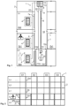
- Fig. 2 shows a side view of a schematically illustrated building 2 with an exemplary elevator system 1 with a group of four elevators E1, E2, E3, E4, each having an elevator car 10 with two car doors 10a, 10b.
- the elevators E1-E4 serve the floors L0, L, L1, L2, Ln.
- On the access control floor L it is indicated for each elevator E1-E4 that access is possible from and to the public zone Zp1 and from and to the non-public zone Zs1.
- On the access floor L0 it is indicated for each elevator E1-E4 that access is possible from and to the public zone Zp2.
- On the usage floors L1-Ln access is only possible from and to the non-public zone Zs, Zs2.
- not all elevators E1-E4 in the group each have two car doors 10a, 10b.
- elevators E1 and E2 may each have two car doors 10a, 10b, while elevators E3 and E4 each have only one car door 10a, 10b.
- elevators E3 and E4 only serve floors L, L1, L2, Ln, while elevators E1 and E2, as in the previous embodiment, serve all floors L0, L, L1, L2, Ln.
- Those skilled in the art will recognize that, in general, not all elevators E1-E4 in the group each have two car doors.
- Fig. 2 In this embodiment, the hatched areas for the public zones on the access floor L0 for elevators E3 and E4 can be omitted.
- Fig. 3 shows a plan view of the elevator system 1 according to Fig. 2 on a level of the access control floor L.
- the elevator installation 1 comprises the group of elevators E1 - E4.
- the elevator E1 comprises at least one elevator car 10 ( Fig. 1 ), the remaining elevators E2 - E4 of the group each have an elevator car 10 with a first and a second car door 10a, 10b.
- the elevators E1-E4 are in this Plan view arranged side by side (essentially in a row next to each other). From the perspective of a passenger P, the elevators E1-E4 are also arranged in a row next to each other.
- the car door 10a On the access control floor L, the car door 10a is coupled to the floor door 6 (corresponding to the public zone Zp1), and the car door 10b is coupled to the floor door 7 (corresponding to the non-public zone Zs 1).
- An arrow 26 indicates possible directions of movement on the access control floor L.
- passengers P can exit or enter the elevators E1-E4 towards the public zone Zp1 or the non-public zone Zs 1.
- Fig. 4 shows a plan view of the elevator installation 1 according to a further embodiment in a level of the access control floor L.
- the elevator installation 1 comprises the group of elevators E1 - E4.
- the elevator E1 comprises at least one elevator car 10 ( Fig. 1 ).
- An elevator subgroup comprises the elevators E2 - E4 of the group, each of which has an elevator car 10 with a single car door 10b.
- the elevators E1 - E4 are arranged in building 2 such that on the access control floor L the second car door 10b of the at least one elevator car 10 and the only car doors 10b of the elevator subgroup open towards the first non-public zone Zs 1.
- elevators E1 and E2 are arranged side by side and each have an elevator car 10 and car doors 10a, 10b.
- the car door 10a can be coupled to the floor door 6 (corresponding to the public zone Zp1)
- the car door 10b can be coupled to the floor door 7 (corresponding to the non-public zone Zs1).
- Elevators E3 and E4 are also arranged side by side in this plan view and each have an elevator car 10; each of these elevator cars 10, however, has only one car door 10b, which can be coupled to the floor door 7 (corresponding to the non-public zone Zs1) on the access control floor L.
- Fig. 4 It can be seen that the lifts E1 and E2 are located opposite the lifts E3 and E4, with the non-public zone Zs1 being located between the lifts E1, E2 and the lifts E3, E4.
- Fig. 4 In the embodiment of the Fig. 4 are from the perspective of a passenger P in public In zone Zp1, only elevators E1 and E2 are visible.
- An arrow 28 indicates possible directions of movement on the access control floor L.
- passengers P can exit or enter elevators E1 and E2 toward the public zone Zp1 or the non-public zone Zs1; however, elevators E3 and E3 can only be exited or entered toward the non-public zone Zs1.
- the elevator installation 1 can be equipped with an up/down control or with a destination call control.
- the person skilled in the art will recognize that other elevator controls, e.g. controls with mobile devices or hybrid forms of the aforementioned controls, are also possible.
- elevator operating devices 4 are arranged on the floors L, L0, Ln, at which a passenger P can enter the desired direction of travel.
- the boarding floor results from the location of the elevator operating device 4 at which the direction of travel (i.e., an elevator call) is entered.
- the desired destination floor is then entered in the cabin 10 at an elevator operating device arranged there (in Fig. 1 not shown).
- a communication line 20 connects the (car-side) elevator operating device to the elevator control 13.
- the elevator operating devices 4 are arranged on the floors L, L0, Ln, at which a passenger P can enter a desired destination floor; after the passenger P has entered the destination floor (i.e., entering a destination call), information about the boarding floor and the destination floor is available.
- the boarding floor is determined from the location of the elevator operating device 6 at which the destination floor is entered.
- a destination call control device 12 assigns an elevator car 10 to the entered destination call, and an elevator control device 8 controls the movement of the assigned elevator car 10 according to the destination call.
- Fig. 5 Fig. 6
- Fig. 7 Descriptions of exemplary methods for operating the elevator system 1.
- the elevator system 1 can be operated as in Fig. 1 shown; several elevators E1-E4 can be arranged as shown in Fig. 2 or Fig. 3
- the methods are illustrated by means of exemplary flow charts and the steps steps. The skilled person will recognize that the division into these steps is exemplary and that one or more of these steps can be divided into one or more sub-steps or that several of the steps can be combined into one step.
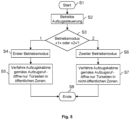
- Fig. 5 shows an exemplary representation of a first embodiment of a method for operating the elevator installation 1.
- the method begins in a step S1 and ends in a step S8.
- the elevator control 13 of the elevator installation 1 is operated according to a first operating mode or a second operating mode. Operation can take place according to one of the two operating modes, which is represented by a decision in a step S3. If operation is to take place according to the first operating mode, the method proceeds along the "1" branch to a step S4, in which the first operating mode is specified as the operating mode. If operation is to take place according to the second operating mode, the method proceeds along the "2" branch to a step S6, in which the second operating mode is specified as the operating mode.
- the elevator control 13 controls the elevator car 10 so that it travels between the floors L, L0 and serves the public zones Zp1, Zp2. This also means that the elevator control 13 only accepts elevator calls from and to floors L, L0 with public zones Zp1, Zp2 for operation or execution.
- the elevator control 13 controls the opening of the car door 10a on a floor L, L0 to be served, which causes the shaft door 6, 6a located in the public zone Zp1, Zp2 on the floor L, L0 to be served to open.
- the car door 10a on the floor L, L0 to be served takes the corresponding shaft door 6 with it.
- the elevator control 13 controls the elevator car 10 so that it travels between the floors L, Ln and serves the non-public zones Zs1, Zs2. This also means that the elevator control 13 accepts elevator calls only from and to floors L, Ln with non-public zones Zs1, Zs2 for operation or execution.
- the elevator control 13 controls an opening on a floor L, Ln to be served.
- the car door 10b that causes the shaft door 7, 7a located in the non-public zone Zs1, Zs2 on the floor to be served, L, Ln, to open.
- the car door 10b on the floor to be served, L, L0 also takes the corresponding shaft door 7, 7a with it.
- step S8 ends in step S8 after step S5 or step S7.
- Fig. 6 shows an exemplary representation of a second embodiment of a method for operating the elevator installation 1.
- the method begins in a step A1 and ends in a step A16.
- the description of this embodiment is based on a situation in which the Fig. 1 the elevator car 10 shown is empty, which is detected by the monitoring device 24, and no elevator call is to be served; step A2 represents this situation.
- an elevator call from a passenger P is received.
- the elevator call can be a destination call or indicate the direction of travel.
- the boarding floor is determined.
- the boarding floor is determined from the floor L, L0, Ln on which the elevator operating device 4, at which the passenger P enters the elevator call, is located.
- the passenger P can be in a public zone Zp or a non-public zone Zs.
- the type of zone (Zp, Zs) in which the passenger P is located and from which the passenger P must enter the elevator car 10 is also determined. Determining the zone type therefore also includes which of the elevator doors 10a, 10b on the boarding floor is to be opened.
- the elevator operating device 4 used by the passenger P can also be located in one of the two zones Zp, Zs. In one exemplary embodiment, the type of zone can thus be determined for this elevator call.
- step A5 it is checked whether the zone is a public zone Zp1, Zp2. If this is the case, the method proceeds along the YES branch to step A6. If, however, it is a non-public zone Zs1, Zs2, the method proceeds along the NO branch to step A11 .
- step A6 the first operating mode is set for the elevator control system 13. Since the elevator car 10 is empty (step A2), the technology described here allows switching from one operating mode to the other.
- the elevator control 13 In the first operating mode, the elevator control 13 only accepts elevator calls from and to floors L, L0 with public zones Zp1, Zp2, and only the doors to the public zones Zp1, Zp2 are opened (see also step S5 in Fig. 5 ).
- step A8 the elevator call of passenger P and any elevator calls of other passengers (which can be served in the first operating mode) are served. Elevator car 10 should therefore be empty.
- step A9 a check is made to determine whether the elevator car 10 is empty. For this purpose, the signal from the monitoring device 24 is evaluated. If the elevator car 10 is empty, the method proceeds along the YES branch to step A16, where the method ends or returns to the start in step A1 .
- step A10 an alarm is generated, which, for example, alerts building personnel that there may be unauthorized use of the elevator and/or which triggers the information unit 25 in the elevator car 10 to generate an audiovisual notification prompting a passenger to exit the elevator car 10.
- the method can wait a predetermined period of time and then check again in step A9 whether the elevator car 10 is empty. This query can be repeated until the elevator car 10 is empty.
- step A5 the method proceeds along the NO branch to step A11 if the zone is a non-public zone Zs1, Zs2.
- step A11 the second operating mode is set for the elevator control 13. Since the elevator car 10 is empty (step A2), it is possible to switch from one operating mode to the other according to the technology described here.
- step A12 the elevator call is served according to the second operating mode.
- the elevator control 13 In this operating mode, the elevator control 13 only accepts elevator calls from and to floors L, Ln with non-public zones Zs1, Zs2, and only the doors to the non-public zones Zs1, Zs2 are opened (see also step S7 in Fig. 5 ).
- steps A13-A15 in this branch are executed as described in conjunction with steps A8-A10 .
- steps A8-A10 and A13-A15 ensure that the elevator car 10 is empty before switching from one operating mode to the other (see steps A2, A6, and A11 ).
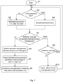
- Fig. 7 shows an exemplary representation of a third embodiment of a method for operating the elevator installation 1. The method begins in a step B1 and runs through loops which, in this embodiment, lead back to a step B2 .
- step B2 a check is performed to determine whether the elevator car 10 is empty. For this purpose, the signal from the monitoring device 24 is evaluated. If the elevator car 10 is empty, the method proceeds along the YES branch to step B3, where it is determined that the operating mode can be the first operating mode or the second operating mode. If, however, the elevator car 10 is not empty, the method proceeds along the NO branch to step B4, where the current operating mode of the elevator controller 13 is maintained. Because the elevator car 10 is not empty, the operating mode cannot be changed according to the technology described here (at the time step B2 is executed) .
- Steps B3 and B4 are followed by step B5.
- step B5 a check is made to determine whether at least one elevator call is present according to the operating mode defined in steps B3 (both operating modes are possible (either the first or the second operating mode) or B4 (current operating mode is maintained). If such an elevator call is present, the method proceeds along the YES branch to step B6; otherwise, it proceeds along the NO branch to step B9.
- step B6 the present elevator call is analyzed to plan the next stop of the elevator car 10 required for this purpose by the elevator control system 13.
- the floor to be served and the car door 10a, 10b are selected, which is to be opened upon stopping on the floor to be served according to the elevator call and the operating mode.
- step B7 the operating mode is set according to the stop selected for the elevator call in step B6 .
- the operating mode can be set to the first operating mode or the second operating mode. There are two cases here: If the operating mode has already been set (i.e., to the first or second operating mode), then the elevator call definitely matches the operating mode, and the operating mode is retained. On the other hand, i.e., if the operating mode (according to step B3) is still selectable, it is now set in step B7 to match the elevator call, which either only affects public zones Zp (first operating mode) or non-public zones Zs (second operating mode).
- step B8 the elevator car 10 is moved to the floor to be served in order to operate the stop.
- the car door 10a, 10b selected in step B6 is opened and closed again, with the corresponding floor door 6, 6a, 7, 7a being moved along by the car door 10a, 10b.
- the elevator call is thus served, and the process returns to step B2.
- step B9 after no further elevator call according to the operating mode defined in steps B3 or B4 is present in step B5 , a check is made to determine whether another elevator call is present that requires a different operating mode. If no such elevator call is present, the method proceeds along the NO branch back to step B2; otherwise, it proceeds along the YES branch to step B10.
- step B10 an alarm is generated as described in connection with step A10 in Fig. 6 described.
- the car door 10a, 10b and the corresponding floor door 6, 6a, 7, 7a are opened until the elevator car 10 is empty. If this is the case, the alarm can be terminated. The process then returns to step B2.
- passenger P enters the elevator call on the elevator operating device 4 (shown as a destination call device). If the elevator car 10 is ready for boarding, i.e. the shaft door 6b and the car door 10a are open, passenger P gets into the car 10. In one embodiment, the information unit 25 arranged in the car 10 informs the passenger P that the car 10 is traveling to the access control floor L and that he or she must get off there. If the car 10 is on the access control floor L, passenger P enters the first public zone Zp1 through the open car door 10a and the open shaft door 6a. The monitoring device 24 checks whether the car 10 is then empty.
- passenger P In order to begin the journey to the desired floor Ln after being registered by staff, passenger P goes to the first non-public zone Zs1 on the access control floor L. At the elevator operating device 4 located there, passenger P enters the desired floor Ln (destination call). If the check by the monitoring device 24 shows that the car 10 is empty, the elevator control 13 switches to the second operating mode. If the elevator car 10 is ready for boarding, i.e., the shaft door 7 and the car door 10b are open, passenger P enters the car 10 and is transported to the desired floor Ln.
Landscapes
- Engineering & Computer Science (AREA)
- Automation & Control Theory (AREA)
- Computer Networks & Wireless Communication (AREA)
- Elevator Door Apparatuses (AREA)
- Elevator Control (AREA)
- Types And Forms Of Lifts (AREA)
- Indicating And Signalling Devices For Elevators (AREA)
Description
- Die hier beschriebene Technologie betrifft allgemein eine Aufzugsanlage in einem Gebäude. Ausführungsbeispiele der Technologie betreffen insbesondere eine Aufzugsanlage mit einer Zugangskontrollfunktion und ein Verfahren zum Betreiben einer solchen Aufzugsanlage.
- Der Zugang zu einem Gebäude oder Zugänge zu zugangsbeschränkten Zonen innerhalb des Gebäudes können auf verschiedene Arten kontrolliert werden. Beispielsweise kann ein Zugangskontrollsystem eine physische Barriere (z. B. Tür, Schranke oder Schleusen) entriegeln und für einen Nutzer freigeben, wenn der Nutzer einen gültigen Berechtigungsnachweis vorweist; je nach im Zugangskontrollsystem eingesetzter Technologie beispielsweise einen Schlüssel, einen Zugangscode (PIN, optischer Code (Barcode, QR Code, Farbcode). Aus
EP 2 588 399 B1 ist bekannt, dass eine Zugangskontrollfunktion auch in Verbindung mit einer Aufzugsanlage erfolgen kann.KR 2009 0019620 A - Obwohl die genannten Ansätze den Zugang zu einem Gebäude oder dessen zugangsbeschränkten Zonen kontrollieren, kann in einem Gebäude eine Anforderung nach einer zusätzlichen Kontrollfunktionalität bestehen, ohne dabei aufwändige Änderungen am Gebäude oder dessen Infrastruktur vorzusehen. Es besteht daher ein Bedarf an einer Technologie, die diese Anforderung ganz oder zumindest teilweise erfüllt.
- Ein Aspekt der hier beschriebenen Technologie betrifft eine Aufzugsanlage, die eine Aufzugssteuerung, mindestens eine Aufzugskabine und eine Anzahl von Schachttüren hat. Die Aufzugskabine ist gesteuert durch die Aufzugsteuerung zwischen Stockwerken eines Gebäudes in einem Aufzugsschacht verfahrbar und hat zwei Kabinentüren, eine erste Kabinentür an einer ersten Kabinenwand und eine zweite Kabinentür an einer zweiten Kabinenwand. Die Schachttüren trennen den Aufzugsschacht von den Stockwerken, wobei eine erste Gruppe von Schachttüren in öffentlichen Zonen des Gebäudes und eine zweite Gruppe von Schachttüren in nicht öffentlichen Zonen des Gebäudes angeordnet sind. Die Aufzugssteuerung aufweist einen ersten Betriebsmodus und einen zweiten Betriebsmodus auf. Im ersten Betriebsmodus ist die Aufzugssteuerung ausgestaltet, die Aufzugskabine zwischen den Stockwerken zu verfahren und die öffentlichen Zonen zu bedienen. Auf einem zu bedienenden Stockwerk steuert die Aufzugssteuerung ein Öffnen derjenigen Kabinentür, die auf dem zu bedienenden Stockwerk ein Öffnen der in der dortigen öffentlichen Zone angeordneten Schachttür veranlasst. Im zweiten Betriebsmodus ist die Aufzugssteuerung ausgestaltet, die Aufzugskabine zwischen den Stockwerken zu verfahren, um die nicht öffentlichen Zonen zu bedienen. Auf einem zu bedienenden Stockwerk steuert die Aufzugssteuerung ein Öffnen derjenigen Kabinentür, die auf dem zu bedienenden Stockwerk ein Öffnen der in der dortigen nicht öffentlichen Zone angeordneten Schachttür veranlasst.
- Ein weiterer Aspekt der hier beschriebenen Technologie betrifft ein Verfahren zum Betreiben einer Aufzugsanlage. Die Aufzugsanlage ist dabei wie im vorhergehenden Absatz beschrieben ausgestaltet. Das Verfahren umfasst ein Betreiben der Aufzugssteuerung gemäss einem ersten Betriebsmodus oder einem zweiten Betriebsmodus. Im ersten Betriebsmodus wird die Aufzugskabine gesteuert durch die Aufzugssteuerung zwischen den Stockwerken verfahren, um die öffentlichen Zonen zu bedienen, wobei durch die Aufzugssteuerung auf einem zu bedienenden Stockwerk ein Öffnen derjenigen Kabinentür gesteuert wird, die auf dem zu bedienenden Stockwerk ein Öffnen der in der dortigen öffentlichen Zone angeordneten Schachttür veranlasst. Im zweiten Betriebsmodus wird die Aufzugskabine gesteuert durch die Aufzugssteuerung zwischen den Stockwerken verfahren, um die nicht öffentlichen Zonen zu bedienen, wobei durch die Aufzugssteuerung auf einem zu bedienenden Stockwerk ein Öffnen derjenigen Kabinentür gesteuert wird, die auf dem zu bedienenden Stockwerk ein Öffnen der in der dortigen nicht öffentlichen Zone angeordneten Schachttür veranlasst.
- Durch die hier beschriebene Technologie wird ermöglicht, eine Aufzugsanlage mit einer im Vergleich zum Stand der Technik alternativen Zugangskontrollfunktion auszustatten. Die Aufzugssteuerung hat einen ersten Betriebsmodus und einen zweiten Betriebsmodus und kann zwischen diesen beiden Betriebsmodi wechseln. Im ersten Betriebsmodus verfährt die Aufzugssteuerung die Aufzugskabine nur von und zu Stockwerken mit öffentlichen Zonen, und im zweiten Betriebsmodus verfährt die Aufzugssteuerung die Aufzugskabine nur von und zu Stockwerken mit nicht öffentlichen Zonen. Damit kann im Gebäude ein Stockwerk festgelegt werden, das als Zugangskontrollstockwerk dient; dort kann sich beispielsweise ein Empfangsbereich einer Unternehmung oder eine Rezeption eines Hotels befinden. Ein Passagier, der beispielsweise das Gebäude über eine öffentliche Gebäudezone betritt und dort einen Aufzugsruf eingibt, kann durch die Aufzugsanlage anfangs nur in eine andere öffentliche Gebäudezone, insbesondere auf dem Zugangskontrollstockwerk, transportiert werden. Nachdem er im Empfangsbereich oder der Rezeption erfasst wird, kann er sich in die nicht öffentliche Zone auf dem Zugangskontrollstockwerk begeben, um von dort aus auf ein gewünschtes Nutzungsstockwerk im Gebäude befördert zu werden.
- Die hier beschriebene Technologie ermöglicht es zudem, dass das Zugangskontrollstockwerk in der genannten Weise bedient werden kann, ohne dass ein zusätzlicher Shuttle-Aufzug erforderlich ist, der nur die Stockwerke mit öffentlichen Zonen bedient. Die beiden Betriebsmodi erlauben es nämlich, dass der gleiche Aufzug (und damit z. B. auch der gleiche Aufzugsschacht) sowohl für Fahrten zwischen Stockwerken mit öffentlichen Zonen als auch für Fahrten zwischen Stockwerken mit nicht öffentlichen Zonen genutzt werden kann. Da kein Shuttle-Aufzug benötigt wird, ist im Gebäude weniger Raum für die Aufzugsanlage erforderlich. Das Gebäude kann dann beispielsweise mit einer kleineren Grundfläche geplant und gebaut werden, oder der nicht mehr benötige Raum steht für eine andere Nutzung zur Verfügung. Der geringere Platzbedarf der Aufzugsanlage ermöglicht beispielsweise Architekten mehr Freiheiten in der Planung und Gestaltung von Gebäuden.
- In einem Ausführungsbeispiel wird die Zugangskontrollfunktion dadurch unterstützt, dass ein Wechsel zwischen den beiden Betriebsmodi nur dann möglich ist, wenn ein von einer Überwachungseinrichtung erzeugtes Statussignal anzeigt, dass kein Passagier in der Aufzugskabine anwesend ist. D. h. es kann in einem Ausführungsbeispiel geprüft werden, ob die Aufzugskabine leer ist, bevor ein Wechsel des Betriebsmodus erfolgt. In einem Ausführungsbeispiel ist die Überwachungseinrichtung in der Aufzugskabine angeordnet.
- In einem Ausführungsbeispiel ist in der Aufzugskabine eine Informationseinheit angeordnet, die mit der Aufzugssteuerung kommunikativ verbunden ist. Die Informationseinheit erzeugt gesteuert durch die Aufzugssteuerung eine Benachrichtigung, insbesondere eine audiovisuelle Benachrichtigung, die den Passagier auffordert, aus der Aufzugskabine auszusteigen, beispielsweise wenn die Aufzugskabine das Zielstockwerk ankommt und die Aufzugssteuerung den Betriebsmodus zu wechseln hat.
- In einem Ausführungsbeispiel erzeugt die Informationseinheit eine Benachrichtigung, die den Passagier darüber informiert, dass lediglich Stockwerke mit öffentlichen Zonen, insbesondere das Zugangskontrollstockwerk, bedient werden. Eine solche Benachrichtigung erfolgt beispielsweise dann, wenn der Passagier von einer öffentlichen Zone aus in die Aufzugskabine einsteigt. Die Benachrichtigung kann den Passagier zudem informieren oder auffordern, sich zur Rezeption zu begeben.
- Zusätzlich oder als Alternative zur Benachrichtigung des Passagiers in der Aufzugskabine kann in einem Ausführungsbeispiel die Benachrichtigung des Passagiers bereits in der öffentlichen Zone auf einem Stockwerk erfolgen. Durch die genannten Möglichkeiten zur Benachrichtigung des Passagiers, wird der Passagier bei der Nutzung der Aufzugsanlage und der Orientierung im Gebäude unterstützt.
- Die hier beschriebene Technologie ist nicht auf eine Aufzugsanlage mit einem einzigen Aufzug beschränkt; sie kann auch in Verbindung mit einer Aufzugsgruppe oder mehreren Aufzugsgruppen eingesetzt werden. In einem Ausführungsbeispiel, hat die Aufzugsanlage eine Gruppe von Aufzügen, wobei ein Aufzug dieser Aufzugsgruppe die mindestens eine Aufzugskabine umfasst und die übrigen Aufzüge der Gruppe jeweils eine Aufzugskabine mit einer ersten und einen zweiten Kabinentür haben. In diesem Ausführungsbeispiel hat somit jede Aufzugskabine an zwei Kabinenwänden jeweils eine Kabinentür. In einem Ausführungsbeispiel sind die Aufzüge der Aufzugsgruppe im Gebäude in einer Reihe nebeneinander angeordnet.
- In einem Ausführungsbeispiel sind nicht alle Aufzugskabinen einer Aufzugsgruppe mit derartigen zwei Kabinentüren ausgestattet. Die hierbeschriebene Technologie ermöglicht diesbezüglich Gestaltungsfreiheit, wodurch Kosteneinsparungen möglich sind, ohne die durch die Technologie bereitgestellte Zugangskontrollfunktion einzuschränken.
- In einer Aufzugsgruppe ist die Anordnung der Aufzüge nicht auf die genannte Anordnung in einer Reihe beschränkt. In einem Ausführungsbeispiel hat eine Aufzugsuntergruppe Aufzüge, die jeweils eine Aufzugskabine mit einer einzigen Kabinentür haben. Der übrige Teil (einer oder mehrere Aufzüge) der Aufzugsgruppe hat die jeweilige Aufzugskabine zwei Kabinentüren. Die Aufzüge der Aufzugsgruppe sind im Gebäude so angeordnet, dass auf dem Zugangskontrollstockwerk die zweite Kabinentür der mindestens einen Aufzugskabine und die einzigen Kabinentüren der Aufzugsuntergruppe zur ersten nicht öffentlichen Zone hin öffnen. Die nicht öffentliche Zone befindet sich dadurch im Raum zwischen der Aufzugsuntergruppe und dem übrigen Teil der Aufzugsgruppe.
- Im Folgenden sind verschiedene Aspekte der verbesserten Technologie anhand von Ausführungsbeispielen in Verbindung mit den Figuren näher erläutert. In den Figuren haben gleiche Elemente gleiche Bezugszeichen. Es zeigen:
- Fig. 1
- eine schematische Darstellung einer beispielhaften Situation in einem Gebäude mit mehreren Stockwerken und einer beispielhaften Aufzugsanlage;
- Fig. 2
- eine Seitenansicht eines schematisch dargestellten Gebäudes mit einer beispielhaften Aufzugsanlage mit vier Aufzügen;
- Fig. 3
- eine Draufsicht auf die Aufzugsanlage gemäss
Fig. 2 in einer Ebene eines Zugangskontrollstockwerks; - Fig. 4
- eine Draufsicht auf die Aufzugsanlage gemäss einem weiteren Ausführungsbeispiel in einer Ebene des Zugangskontrollstockwerks;
- Fig. 5
- eine beispielhafte Darstellung eines ersten Ausführungsbeispiels eines Verfahrens zum Betreiben der Aufzugsanlage;
- Fig. 6
- eine beispielhafte Darstellung eines zweiten Ausführungsbeispiels eines Verfahrens zum Betreiben der Aufzugsanlage; und
- Fig. 7
- eine beispielhafte Darstellung eines dritten Ausführungsbeispiels eines Verfahrens zum Betreiben der Aufzugsanlage.
-
Fig. 1 ist eine schematische Darstellung einer beispielhaften Situation in einem Gebäude 2, das mehrere Stockwerke L0, L, Ln hat, die von einer Aufzugsanlage 1 bedient werden. Gemäss einem Ausführungsbeispiel der hier beschriebenen Technologie erfolgt auf dem Stockwerk L eine Gebäude-interne Zugangskontrolle; im Folgenden ist das Stockwerk L auch als Zugangskontrollstockwerk L bezeichnet. In der inFig. 1 gezeigten Situation hat das Gebäude 2 mindestens ein Stockwerk L0 unterhalb des Zugangskontrollstockwerks L und mehrere Stockwerke Ln oberhalb des Zugangskontrollstockwerks L. Personen können das Gebäude 2 beispielsweise auf dem Stockwerk L0 betreten, um eines oder mehrere der Stockwerke Ln für einen bestimmten Zweck zu nutzen. Im Folgenden ist das Stockwerk L0 auch als Zugangsstockwerk L0 bezeichnet, und ein Stockwerk Ln ist auch als Nutzungsstockwerk Ln bezeichnet. Der Fachmann erkennt, dass die Bezeichnungen "Zugangskontrollstockwerk", "Zugangsstockwerk" und "Nutzungsstockwerk" beispielhaft sind und hier zur besseren Unterscheidung der Stockwerke L0, L, Ln gewählt sind. Der Fachmann erkennt zudem, dass die Anordnung und/oder Organisation der Stockwerke L0, L, Ln an das Gebäude 2 und dessen Nutzung angepasst sind und entsprechend dazu auf eine andere Art und Weise als inFig. 1 gezeigt ausgeführt sein können. - Aus Darstellungsgründen sind in
Fig. 1 von der Aufzugsanlage 1 nur eine Aufzugssteuerung 13, eine Antriebsmaschine 14, ein Tragmittel 16 (z. B. Stahlseile oder Flachriemen), eine am Tragmittel 16 hängende und durch die Aufzugsteuerung 13 gesteuert in einem Schacht 18 verfahrbare Aufzugskabine 10 (im Folgenden auch als Kabine 10 bezeichnet) und eine Anzahl von Aufzugsbedieneinrichtungen 4 gezeigt. Der Fachmann erkennt, dass die Aufzugsanlage 1 auch mehrere Kabinen 10 in einem oder mehreren Schächten 18 umfassen kann, die von einer Gruppensteuerung gesteuert werden. Anstelle eines inFig. 1 dargestellten Traktionsaufzuges kann die Aufzugsanlage 1 auch einen oder mehrere Hydraulikaufzüge aufweisen. - Die in
Fig. 1 gezeigte Aufzugskabine 10 hat eine erste Kabinentür 10a an einer ersten Kabinenwand 10d und eine zweite Kabinentür 10b an einer zweiten Kabinenwand 10c. Im gezeigten Ausführungsbeispiel sind in der Kabine 10 eine Überwachungseinrichtung 24 und eine Informationseinrichtung 25 angeordnet, die mit der Aufzugssteuerung 13 kommunikativ verbunden sind. Die Überwachungseinrichtung 24 ist ausgestaltet, ein Statussignal zu erzeugen, das anzeigt, ob ein Passagier P in der Aufzugskabine 10 anwesend ist. Die Überwachungseinrichtung 24 kann z. B. eine Videokamera mit einer dazugehörigen Bildverarbeitungseinrichtung umfassen; damit kann die Anwesenheit eines Passagiers P erkannt werden. Der Fachmann erkennt, dass die Aufzugsanlage 1 auch zum Transport von einem autonom verfahrbaren Objekt (Roboter) oder einem anderen Objekt genutzt werden kann; der Begriff "Passagier" umfasst daher auch solche Objekte. -
Fig. 1 zeigt zudem eine Anzahl von Schachttüren 6a, 6b, 7, 7a, die den Aufzugsschacht 18 von den Stockwerken L0, L, Ln trennen. Eine Schachttür 6a, 6b, 7, 7a wird in einem Ausführungsbeispiel dadurch geöffnet und geschlossen, dass sie an eine der Kabinentüren 10a, 10b gekoppelt wird, wenn sich die Aufzugskabine 10 auf dem Stockwerk L0, L, Ln befindet und dadurch von der Kabinentür 10a, 10b mitbewegt werden kann. Im Ausführungsbeispiel derFig. 1 sind auf dem Zugangskontrollstockwerk L eine erste Schachttür 6 in einer ersten öffentlichen Zone Zp1 des Gebäudes 2 und eine zweite Schachttür 7 in einer ersten nicht öffentlichen Zone Zs1 des Gebäudes 2 angeordnet. Auf dem Zugangsstockwerk L0 ist eine dritte Schachttür 6a in einer zweiten öffentlichen Zone Zp2 des Gebäudes angeordnet. Auf dem Nutzungsstockwerk Ln ist eine vierte Schachttür 7a in einer zweiten nicht öffentlichen Zone Zs2 angeordnet. Der Fachmann erkennt, dass im Gebäude weitere öffentliche und nicht öffentliche Zonen Zp, Zs vorgesehen sein können. - Ein Kommunikationsnetzwerk 22 verbindet die Aufzugsbedieneinrichtungen 4 mit der Aufzugssteuerung 13 und ermöglicht dadurch eine Kommunikation zwischen der Aufzugssteuerung 13 und den Aufzugsbedieneinrichtungen 4. Für diese Kommunikation können die Aufzugsbedieneinrichtungen 4 und die Aufzugssteuerung 13 direkt oder indirekt mit dem Kommunikationsnetzwerk 22 verbunden sein. Das Kommunikationsnetzwerk 22 kann ein Kommunikationsbussystem, einzelne Datenleitungen oder eine Kombination daraus umfassen. Je nach Implementierung des Kommunikationsnetzwerkes 22 können der Aufzugssteuerung 13 und jeder Aufzugsbedieneinrichtung 4 individuelle Adressen und/oder Kennungen zugeteilt sein, so dass beispielsweise die Aufzugssteuerung 13 eine Nachricht gezielt an eine gewünschte Aufzugsbedieneinrichtung 4 senden kann. Die Kommunikation kann gemäss einem Protokoll für leitungsgebundene Kommunikation, beispielsweise dem Ethernet Protokoll, erfolgen. In einem Ausführungsbeispiel erfolgt die Versorgung der Aufzugsbedieneinrichtungen 4 mit elektrischer Energie über das Kommunikationsnetzwerk 22 (PoE). Ist die Aufzugsbedieneinrichtung 4 in der Kabine 10 angeordnet, dient die Kommunikationsleitung 20 in einem Ausführungsbeispiel zur Kommunikation und zur Energieversorgung der Aufzugsbedieneinrichtung 4.
- In der in
Fig. 1 gezeigten Situation und gemäss einem Ausführungsbeispiel der Aufzugsanlage 1 und deren Betriebsweise wird im Gebäude 2 unter Nutzung der Aufzugsanlage 1 eine Kontrollfunktionalität zur Verfügung gestellt. Kurz und beispielhaft zusammengefasst sind in der Aufzugsanlage 1 gemäss der hier beschriebenen Technologie zwei Betriebsmodi vorgesehen. In einem ersten Betriebsmodus verfährt die Aufzugssteuerung 13 die Aufzugskabine 10 zwischen den Stockwerken L, L0 und bedient die öffentlichen Zonen Zp1, Zp2. Die Aufzugssteuerung 13 steuert dabei auf einem der zu bedienenden Stockwerke L, L0 ein Öffnen derjenigen Kabinentür 10a, 10b, die auf dem zu bedienenden Stockwerk L, L0 ein Öffnen der in der dortigen öffentlichen Zone Zp1, Zp2 angeordneten Schachttür 6, 6a veranlasst. In einem zweiten Betriebsmodus verfährt die Aufzugssteuerung 13 die Aufzugskabine 10 zwischen den Stockwerken L, Ln und bedient die nicht öffentlichen Zonen Zs1, Zs2. Die Aufzugssteuerung 13 steuert dabei auf einem der zu bedienenden Stockwerke L, Ln ein Öffnen derjenigen Kabinentür 10a, 10b, die auf dem zu bedienenden Stockwerk L, Ln ein Öffnen der in der dortigen nicht öffentlichen Zone Zp1, Zp2 angeordneten Schachttür 7, 7a veranlasst. Wie an anderer Stelle dieser Beschreibung ausgeführt, erfolgt ein Wechsel des Betriebsmodus nur, wenn die Aufzugskabine 10 leer ist. - Möchte ein Passagier P gemäss einem Ausführungsbeispiel von der öffentlichen Zone Zp2 auf dem Zugangsstockwerk L0 mit einem Aufzug auf das Nutzungsstockwerk Ln und in die dortige nicht öffentlichen Zone Zs2 fahren, transportiert ihn die Aufzugskabine 10 zuerst auf das Zugangskontrollstockwerk L. Die Aufzugsanlage 1 befindet sich dafür im ersten Betriebsmodus und verfährt die Aufzugskabine 10 nur von und zu Stockwerken L0, L mit öffentlichen Zonen Zp1, Zp2. Steigt der Passagier P auf dem Zugangskontrollstockwerk L aus der Kabine 10 und betritt die öffentliche Zone Zp1, kann der Passagier P dort erfasst werden (z. B. gesehen, erkannt, begrüsst und/oder registriert). In diesem Ausführungsbeispiel ist die Aufzugskabine 10 dann leer und ein Wechsel vom ersten Betriebsmodus in den zweiten Betriebsmodus kann erfolgen. Im zweiten Betriebsmodus wird die Aufzugskabine 10 nur von und zu Stockwerken L0, Ln mit nicht öffentlichen Zonen Zs1, Zs2 verfahren. Begibt sich der Passagier P in diesem Ausführungsbeispiel dann auf dem Zugangskontrollstockwerk L von der öffentlichen Zone Zp1 in die nicht öffentliche Zone Zs1, kann er von dort in die Kabine 10 einsteigen, um auf das gewünschte Nutzungsstockwerk Ln transportiert zu werden.
- Das Zugangskontrollstockwerk L kann beispielsweise einen Empfangsbereich einer Unternehmung oder eine Rezeption eines Hotels umfassen, während sich Nutzungsräume der Unternehmung bzw. Hotelzimmer auf dem mindestens einen Nutzungsstockwerk Ln befinden. In der Unternehmung oder dem Hotel kann festgelegt sein, dass jeder Passagier P, unabhängig davon, ob er bekannt/registriert oder unbekannt ist oder sich regelmässig oder erstmalig im Gebäude 2 aufhält, am Empfangsbereich oder an der Rezeption vorbeigehen muss, um vom dortigen Personal erfasst zu werden. Der Empfangsbereich oder die Rezeption, bzw. deren Personal, auf dem Zugangskontrollstockwerk L tragen somit dazu bei, im Gebäude 2 eine Zugangskontrollfunktion zu implementieren.
- Die Aufzugsanlage 1 kann je nach Art und Grösse des Gebäudes 2 und dessen Transportbedarfs ausgestaltet sein. Verschiedene Ausgestaltungen der Aufzugsanlage 1 sind in
Fig. 2 ,Fig. 3 und Fig. 4 gezeigt.Fig. 2 zeigt eine Seitenansicht eines schematisch dargestellten Gebäudes 2 mit einer beispielhaften Aufzugsanlage 1 mit einer Gruppe von vier Aufzügen E1, E2, E3, E4, die jeweils eine Aufzugskabine 10 mit zwei Kabinentüren 10a, 10b aufweisen. Im gezeigten Ausführungsbeispiel bedienen die Aufzüge E1-E4 die Stockwerke L0, L, L1, L2, Ln. Auf dem Zugangskontrollstockwerk L ist für jeden Aufzug E1-E4 angedeutet, dass dort Zugang von und zu der öffentlichen Zone Zp1 und von und zu der nicht öffentlichen Zone Zs 1 möglich ist. Auf dem Zugangsstockwerk L0 ist für jeden Aufzug E1-E4 angedeutet, dass dort Zugang von und zu der öffentlichen Zone Zp2 möglich ist. Auf den Nutzungsstockwerken L1-Ln ist jeweils nur Zugang von und zur nicht öffentlichen Zone Zs, Zs2 möglich. - In einem anderen Ausführungsbeispiel haben nicht alle Aufzüge E1-E4 der Gruppe jeweils zwei Kabinentüren 10a, 10b. Beispielsweise können die Aufzüge E1 und E2 jeweils zwei Kabinentüren 10a, 10b aufweisen, während die Aufzüge E3 und E4 jeweils nur eine Kabinentür 10a, 10b haben. Die Aufzüge E3 und E4 bedienen in diesem Fall lediglich die Stockwerke L, L1, L2, Ln, während die Aufzüge E1 und E2 wie im vorhergehenden Ausführungsbeispiel die alle Stockwerke L0, L, L1, L2, Ln bedienen. Der Fachmann erkennt, dass allgemein nicht alle Aufzüge E1-E4 der Gruppe jeweils zwei Kabinentüren aufzuweisen haben. In
Fig. 2 können in diesem Ausführungsbeispiel auf dem Zugangsstockwerk L0 bei den Aufzügen E3 und E4 die schraffierten Flächen für die öffentlichen Zonen entfallen. -
Fig. 3 zeigt eine Draufsicht auf die Aufzugsanlage 1 gemässFig. 2 in einer Ebene des Zugangskontrollstockwerks L. Die Aufzugsanlage 1 umfasst die Gruppe von Aufzügen E1 - E4. Der Aufzug E1 umfasst die mindestens eine Aufzugskabine 10 (Fig. 1 ), die übrigen Aufzüge E2 - E4 der Gruppe haben jeweils eine Aufzugskabine 10 mit einer ersten und einen zweiten Kabinentür 10a, 10b. Die Aufzüge E1-E4 sind in dieser Draufsicht nebeneinander (im Wesentlichen in einer Reihe nebeneinander) angeordnet. Aus Sicht eines Passagiers P sind die Aufzüge E1-E4 ebenfalls in einer Reihe nebeneinander angeordnet. Auf dem Zugangskontrollstockwerk L ist die Kabinentür 10a mit der Stockwerktür 6 (entsprechend der öffentlichen Zone Zp1) gekoppelt, und die Kabinentür 10b ist mit der Stockwerktür 7 (entsprechend der nicht öffentlichen Zone Zs 1) gekoppelt. Ein Pfeil 26 deutet mögliche Bewegungsrichtungen auf dem Zugangskontrollstockwerk L an. Je nach Betriebsmodus können Passagiere P die Aufzüge E1-E4 in Richtung der öffentlichen Zone Zp1 oder der nicht öffentlichen Zone Zs 1 verlassen oder von dort aus betreten. -
Fig. 4 zeigt eine Draufsicht auf die Aufzugsanlage 1 gemäss einem weiteren Ausführungsbeispiel in einer Ebene des Zugangskontrollstockwerks L. Die Aufzugsanlage 1 umfasst die Gruppe von Aufzügen E1 - E4. Der Aufzug E1 umfasst die mindestens eine Aufzugskabine 10 (Fig. 1 ). Eine Aufzugsuntergruppe umfasst die Aufzüge E2 - E4 der Gruppe, die jeweils eine Aufzugskabine 10 mit einer einzigen Kabinentür 10b haben, Die Aufzüge E1 - E4 sind im Gebäude 2 so angeordnet, dass auf dem Zugangskontrollstockwerk L die zweite Kabinentür 10b der mindestens einen Aufzugskabine 10 und die einzigen Kabinentüren 10b der Aufzugsuntergruppe zur ersten nicht öffentlichen Zone Zs 1 hin öffnen. - Im gezeigten Ausführungsbeispiel sind die Aufzüge E1 und E2 nebeneinander angeordnet und haben jeweils eine Aufzugskabine 10 und die Kabinentüren 10a, 10b. Für jeden Aufzug E1, E2 gilt, dass auf dem Zugangskontrollstockwerk L die Kabinentür 10a mit der Stockwerktür 6 (entsprechend der öffentlichen Zone Zp1) gekoppelt werden kann, und die Kabinentür 10b kann mit der Stockwerktür 7 (entsprechend der nicht öffentlichen Zone Zs1) gekoppelt werden. Die Aufzüge E3 und E4 sind in dieser Draufsicht ebenfalls nebeneinander angeordnet und haben jeweils eine Aufzugskabine 10; jede dieser Aufzugskabinen 10 hat dagegen nur eine Kabinentür 10b, die auf dem Zugangskontrollstockwerk L mit der Stockwerktür 7 (entsprechend der nicht öffentlichen Zone Zs1) gekoppelt werden kann. In
Fig. 4 ist ersichtlich, dass die Aufzüge E1 und E2 gegenüber den Aufzügen E3 und E4 angeordnet sind, wobei sich die nicht öffentliche Zone Zs1 zwischen den Aufzügen E1, E2 und den Aufzügen E3, E4 befindet. - Im Ausführungsbeispiel der
Fig. 4 sind aus Sicht eines Passagiers P in der öffentlichen Zone Zp1 lediglich die Aufzüge E1, E2 wahrnehmbar. Ein Pfeil 28 deutet mögliche Bewegungsrichtungen auf dem Zugangskontrollstockwerk L an. Je nach Betriebsmodus können Passagiere P die Aufzüge E1 und E2 in Richtung der öffentlichen Zone Zp1 oder der nicht öffentlichen Zone Zs1 verlassen oder von dort aus betreten; die Aufzüge E3 und E3 können dagegen nur in Richtung der nicht öffentlichen Zone Zs1 verlassen oder von dort aus betreten werden. - Die Aufzugsanlage 1 kann mit einer Auf/Ab-Steuerung oder mit einer Zielrufsteuerung ausgestattet sein. Der Fachmann erkennt, dass auch andere Aufzugssteuerungen, z. B. Steuerungen mit mobilen Geräten oder Mischformen der genannten Steuerungen möglich sind. Ist die Aufzugsanlage 1 mit einer Auf/Ab-Steuerung ausgestattet, sind auf den Stockwerken L, L0, Ln Aufzugsbedieneinrichtungen 4 angeordnet, an denen ein Passagier P die gewünschte Fahrtrichtung eingeben kann. Das Einsteigestockwerk ergibt sich aus dem Standort der Aufzugsbedieneinrichtung 4, an der die Fahrtrichtung (d. h. ein Aufzugsruf) eingegeben wird. Die Eingabe des gewünschten Zielstockwerks erfolgt dann in der Kabine 10 an einer dort angeordneten Aufzugsbedieneinrichtung (in
Fig. 1 nicht eingezeichnet). Eine Kommunikationsleitung 20 verbindet die (kabinenseitige) Aufzugsbedieneinrichtung mit der Aufzugssteuerung 13. Ist die Aufzugsanlage 1 mit einer Zielrufsteuerung ausgestattet, sind die Aufzugsbedieneinrichtungen 4 auf den Stockwerken L, L0, Ln angeordnet, an denen ein Passagier P ein gewünschtes Zielstockwerk eingeben kann; nach Eingabe des Zielstockwerks durch den Passagier P (also der Eingabe eines Zielrufs) liegen Angaben über das Einsteigestockwerk und das Zielstockwerk vor. Das Einsteigestockwerk ergibt sich aus dem Standort der Aufzugsbedieneinrichtung 6, an der das Zielstockwerk eingegeben wird. Eine Zielrufsteuereinrichtung 12 teilt dem eingegebenen Zielruf eine Aufzugskabine 10 zu, und eine Aufzugssteuereinrichtung 8 steuert das Verfahren der zugeteilten Aufzugskabine 10 gemäss dem Zielruf. - Mit dem Verständnis der oben beschriebenen prinzipiellen Systemkomponenten der Aufzugsanlage 1 und deren Funktionalitäten, erfolgen im Folgenden anhand von
Fig. 5 ,Fig. 6 undFig. 7 Beschreibungen von beispielhaften Verfahren zum Betreiben der Aufzugsanlage 1. Die Aufzugsanlage 1 kann wie inFig. 1 gezeigt ausgestaltet sein; mehrere Aufzüge E1-E4 können dabei wie inFig. 2 oderFig. 3 gezeigt angeordnet sein. Die Verfahren sind mittels beispielhaften Ablaufdiagrammen und dabei ausgeführten Schritten dargestellt. Der Fachmann erkennt, dass die Aufteilung in diese Schritte beispielhaft ist und dass einer oder mehrere dieser Schritte in einen oder mehrere Teilschritte aufgeteilt oder dass mehrere der Schritte zu einem Schritt zusammengefasst werden können. -
Fig. 5 zeigt eine beispielhafte Darstellung eines ersten Ausführungsbeispiels eines Verfahrens zum Betreiben der Aufzugsanlage 1. Das Verfahren beginnt in einem Schritt S1 und endet in einem Schritt S8. In einem Schritt S2 wird die Aufzugssteuerung 13 der Aufzugsanlage 1 gemäss einem ersten Betriebsmodus oder einem zweiten Betriebsmodus betrieben. Der Betrieb kann gemäss einem der beiden Betriebsmodi erfolgen, was durch eine Entscheidung in einem Schritt S3 dargestellt ist. Hat der Betrieb gemäss dem ersten Betriebsmodus zu erfolgen, schreitet das Verfahren entlang des "1" Zweiges zu einem Schritt S4, in dem als Betriebsmodus der erste Betriebsmodus festgelegt wird. Hat der Betrieb gemäss dem zweiten Betriebsmodus zu erfolgen, schreitet das Verfahren entlang des "2" Zweiges zu einem Schritt S6, in dem als Betriebsmodus der zweite Betriebsmodus festgelegt wird. - Ist im Schritt S4 der erste Betriebsmodus festgelegt, steuert in einem Schritt S5 die Aufzugssteuerung 13 die Aufzugskabine 10 so, dass diese zwischen den Stockwerken L, L0 verfahren wird und die öffentlichen Zonen Zp1, Zp2 bedient werden. Dies bedeutet auch, dass die Aufzugssteuerung 13 Aufzugsrufe nur von und zu Stockwerken L, L0 mit öffentlichen Zonen Zp1, Zp2 zur Bedienung bzw. Ausführung akzeptiert. Die Aufzugssteuerung 13 steuert auf einem zu bedienenden Stockwerk L, L0 ein Öffnen derjenigen Kabinentür 10a, die auf dem zu bedienenden Stockwerk L, L0 ein Öffnen der in der dortigen öffentlichen Zone Zp1, Zp2 angeordneten Schachttür 6, 6a veranlasst. Wie an anderer Stelle dieser Beschreibung ausgeführt, nimmt die Kabinentür 10a auf dem zu bedienenden Stockwerk L, L0 die entsprechende Schachttür 6 mit.
- Ist im Schritt S6 der zweite Betriebsmodus festgelegt, steuert in einem Schritt S7 die Aufzugssteuerung 13 die Aufzugskabine 10 so, dass diese zwischen den Stockwerken L, Ln verfahren wird und die nicht öffentlichen Zonen Zs1, Zs2 bedienen werden. Dies bedeutet auch, dass die Aufzugssteuerung 13 Aufzugsrufe nur von und zu Stockwerken L, Ln mit nicht öffentlichen Zonen Zs1, Zs2 zur Bedienung bzw. Ausführung akzeptiert. Die Aufzugssteuerung 13 steuert auf einem zu bedienenden Stockwerk L, Ln ein Öffnen derjenigen Kabinentür 10b, die auf dem zu bedienenden Stockwerk L, Ln ein Öffnen der in der dortigen nicht öffentlichen Zone Zs1, Zs2 angeordneten Schachttür 7, 7a veranlasst. Auch dabei nimmt die Kabinentür 10b auf dem zu bedienenden Stockwerk L, L0 die entsprechende Schachttür 7, 7a mit.
- Im Ausführungsbeispiel der
Fig. 5 endet das Verfahren im Schritt S8 nach dem Schritt S5 oder dem Schritt S7. -
Fig. 6 zeigt eine beispielhafte Darstellung eines zweiten Ausführungsbeispiels eines Verfahrens zum Betreiben der Aufzugsanlage 1. Das Verfahren beginnt in einem Schritt A1 und endet in einem Schritt A16. Die Beschreibung dieses Ausführungsbeispiels erfolgt ausgehend von einer Situation, in der die inFig. 1 gezeigte Aufzugskabine 10 leer ist, was durch die Überwachungseinrichtung 24 detektiert wird, und kein Aufzugsruf zu bedienen ist; der Schritt A2 repräsentiert diese Situation. - In einem Schritt A3 wird ein Aufzugsruf eines Passagiers P empfangen. Der Aufzugsruf kann ein Zielruf sein oder die Fahrtrichtung anzeigen.
- In einem Schritt A4 wird das Einsteigestockwerk ermittelt. Das Einsteigestockwerk ergibt sich aus dem Stockwerk L, L0, Ln, auf dem die Aufzugsbedieneinrichtung 4, an der der Passagier P den Aufzugsruf eingibt, angeordnet ist. Der Passagier P kann sich dabei in einer öffentlichen Zone Zp oder einer nicht öffentlichen Zone Zs aufhalten. Im Schritt A4 wird zudem die Art der Zone (Zp, Zs) ermittelt, in der sich der Passagier P befindet und von der aus der Passagier P die Aufzugskabine 10 zu betreten hat. Die Ermittlung der Zonenart umfasst daher auch, welche der Aufzugstüren 10a, 10b auf dem Einsteigestockwerk zu öffnen ist. Die vom Passagier P benutzte Aufzugsbedieneinrichtung 4 kann ebenfalls in einer der beiden Zonen Zp, Zs angeordnet sein. In einem Ausführungsbeispiel kann damit für diesen Aufzugsruf die Art der Zone ermittelt werden.
- In einem Schritt A5 wird geprüft, ob die Zone eine öffentliche Zone Zp1, Zp2 ist. Ist dies der Fall, schreitet das Verfahren entlang des JA-Zweigs zu einem Schritt A6. Handelt es sich dagegen um eine nicht öffentliche Zone Zs1, Zs2, schreitet das Verfahren entlang des NEIN-Zweigs zu einem Schritt A11.
- Im Schritt A6 wird für die Aufzugssteuerung 13 der erste Betriebsmodus festgelegt. Da die Aufzugskabine 10 leer ist (Schritt A2), kann gemäss der hier beschriebenen Technologie von einem Betriebsmodus in den anderen Betriebsmodus gewechselt werden.
- In einem dem Schritt A6 nachfolgenden Schritt A7 wird der Aufzugsruf gemäss dem ersten Betriebsmodus bedient. Im ersten Betriebsmodus akzeptiert die Aufzugssteuerung 13 nur Aufzugsrufe von und zu Stockwerken L, L0 mit öffentlichen Zonen Zp1, Zp2, und es werden nur die Türen zu den öffentlichen Zonen Zp1, Zp2 hin geöffnet (siehe auch Schritt S5 in
Fig. 5 ). - In einem Schritt A8 sind der Aufzugsruf des Passagiers P und alle evtl. vorhandenen Aufzugsrufe anderer Passagiere (die im ersten Betriebsmodus bedient werden können) bedient. Die Aufzugskabine 10 sollte daher leer sein.
- In einem Schritt A9 wird geprüft, ob die Aufzugskabine 10 leer ist. Dazu wird das Signal der Überwachungseinrichtung 24 ausgewertet. Ist die Aufzugskabine 10 leer, schreitet das Verfahren entlang des JA-Zweigs zum Schritt A16, in dem das Verfahren endet bzw. zurück zum Start im Schritt A1 schreitet.
- Ist die Aufzugskabine 10 nicht leer, schreitet das Verfahren entlang des NEIN-Zweigs zu einem Schritt A10. Im Schritt A10 wird ein Alarm erzeugt, der beispielsweise Gebäudepersonal darauf hinweist, dass u. U. eine unberechtigte Nutzung des Aufzugs vorliegt und/oder der die Informationseinheit 25 in der Aufzugskabine 10 ansteuert, eine audiovisuelle Benachrichtigung zu erzeugen, die einen Passagier auffordert, aus der Aufzugskabine 10 auszusteigen.
- Nachdem der Alarm im Schritt A10 erzeugt wurde, kann das Verfahren eine vorbestimmte Zeitdauer abwarten, um dann im Schritt A9 erneut zu prüfen, ob die Aufzugskabine 10 leer ist. Diese Abfrage kann solange erfolgen, bis die Aufzugskabine 10 leer ist.
- Im oben genannten Schritt A5 schreitet das Verfahren entlang des NEIN-Zweigs zu einem Schritt A11, wenn es sich um eine nicht öffentliche Zone Zs1, Zs2 handelt. Im Schritt A11 wird für die Aufzugssteuerung 13 der zweite Betriebsmodus festgelegt. Da die Aufzugskabine 10 leer ist (Schritt A2), kann gemäss der hier beschriebenen Technologie von einem Betriebsmodus in den anderen Betriebsmodus gewechselt werden.
- In einem Schritt A12 wird der Aufzugsruf gemäss dem zweiten Betriebsmodus bedient. In diesem Betriebsmodus akzeptiert die Aufzugssteuerung 13 nur Aufzugsrufe von und zu Stockwerken L, Ln mit nicht öffentlichen Zonen Zs1, Zs2, und es werden nur die Türen zu den nicht öffentlichen Zonen Zs1, Zs2 hin geöffnet (siehe auch Schritt S7 in
Fig. 5 ). - Die in diesem Zweig verbleibenden Schritte A13-A15 werden wie in Verbindung mit den Schritten A8-A10 beschrieben ausgeführt. Insbesondere diese Schritte A8-A10 und A13-A15 stellen sicher, dass die Aufzugskabine 10 leer ist, bevor von einem Betriebsmodus in den anderen Betriebsmodus gewechselt werden (vgl. Schritte A2, A6 und A11).
-
Fig. 7 zeigt eine beispielhafte Darstellung eines dritten Ausführungsbeispiels eines Verfahrens zum Betreiben der Aufzugsanlage 1. Das Verfahren beginnt in einem Schritt B1 und durchläuft Schleifen, die in diesem Ausführungsbeispiel zurück zu einem Schritt B2 führen. - Im Schritt B2 wird geprüft, ob die Aufzugskabine 10 leer ist. Dazu wird das Signal der Überwachungseinrichtung 24 ausgewertet. Ist die Aufzugskabine 10 leer, schreitet das Verfahren entlang des JA-Zweigs zu einem Schritt B3, in dem festgelegt wird, dass der Betriebsmodus der erste Betriebsmodus oder der zweite Betriebsmodus sein kann. Ist dagegen die Aufzugskabine 10 nicht leer, schreitet das Verfahren entlang des NEIN-Zweigs zu einem Schritt B4, in dem der momentane Betriebsmodus der Aufzugssteuerung 13 beibehalten wird. Weil die Aufzugskabine 10 nicht leer ist, kann der Betriebsmodus gemäss der hier beschriebenen Technologie (zum Zeitpunkt der Ausführung des Schritts B2) nicht gewechselt werden.
- Den Schritten B3 und B4 folgt ein Schritt B5. Im Schritt B5 wird geprüft, ob mindestens ein Aufzugsruf gemäss dem in den Schritten B3 beide Betriebsmodi sind möglich (entweder der erste oder der zweite Betriebsmodus) oder B4 (momentane Betriebsmodus wird beibehalten) festgelegten Betriebsmodus vorliegt. Liegt ein solcher Aufzugsruf vor, schreitet das Verfahren entlang des JA-Zweigs zu einem Schritt B6, andernfalls entlang des NEIN-Zweigs zu einem Schritt B9.
- Im Schritt B6 wird der vorliegende Aufzugsruf analysiert, um einen dafür erforderlichen nächsten Halt der Aufzugskabine 10 durch die Aufzugssteuerung 13 zu planen. Dabei werden das zu bedienende Stockwerk und die Kabinentür 10a, 10b gewählt, die beim Halt auf dem zu bedienenden Stockwerk gemäss dem Aufzugsruf und dem Betriebsmodus zu öffnen ist.
- In einem Schritt B7 wird der Betriebsmodus gemäss dem im Schritt B6 für den Aufzugsruf gewählten Halt gesetzt. Der Betriebsmodus kann auf den ersten Betriebsmodus oder den zweiten Betriebsmodus gesetzt werden. Hier gibt es zwei Fälle: Ist der Betriebsmodus bereits festgelegt (d. h. auf den ersten oder zweiten Betriebsmodus), dann passt der Aufzugsruf sicher zum Betriebsmodus, und der Betriebsmodus wird beibehalten. Andererseits, d. h. ist der Betriebsmodus (gemäss Schritt B3) noch wählbar, so wird er jetzt im Schritt B7 festgelegt, passend zum Aufzugsruf, welcher entweder nur öffentliche Zonen Zp (erster Betriebsmodus) oder nicht-öffentliche Zonen Zs (zweiter Betriebsmodus) betrifft.
- In einem Schritt B8 wird die Aufzugskabine 10 auf das zu bedienende Stockwerk verfahren, um den Halt zu bedienen. Dabei wird die im Schritt B6 gewählte Kabinentür 10a, 10b geöffnet und wieder geschlossen, wobei die entsprechende Stockwerktür 6, 6a, 7, 7a von der Kabinentür 10a, 10b mitbewegt wird. Damit ist der Aufzugsruf bedient und das Verfahren schreitet zurück zum Schritt B2.
- Im Schritt B9 wird, nachdem im Schritt B5 kein weiterer Aufzugsruf gemäss dem in den Schritten B3 oder B4 festgelegten Betriebsmodus vorliegt, geprüft, ob ein weiterer Aufzugsruf vorliegt, der einen anderen Betriebsmodus erfordert. Liegt kein solcher Aufzugsruf vor, schreitet das Verfahren entlang des NEIN-Zweigs zurück zum Schritt B2, andernfalls entlang des JA-Zweigs zu einem Schritt B10.
- Im Schritt B10 wird ein Alarm erzeugt, wie in Verbindung mit dem Schritt A10 in
Fig. 6 beschrieben. Zusätzlich werden die Kabinentür 10a, 10b und die entsprechende Stockwerktür 6, 6a, 7, 7a geöffnet, bis die Aufzugskabine 10 leer ist. Ist dies der Fall, kann der Alarm beendet werden. Das Verfahren schreitet daraufhin zurück zum Schritt B2. - In einem Ausführungsbeispiel und bezogen auf die in
Fig. 1 gezeigte Situation gibt der Passagier P den Aufzugsruf an der Aufzugsbedieneinrichtung 4 (dargestellt als Zielrufeinrichtung) ein. Ist die Aufzugskabine 10 einsteigebereit, d. h. die Schachttür 6b und die Kabinentür 10a sind geöffnet, steigt der Passagier P in die Kabine 10. In einem Ausführungsbeispiel informiert die in der Kabine 10 angeordnete Informationseinheit 25 den Passagier P, dass die Kabine 10 auf das Zugangskontrollstockwerk L fährt und er dort auszusteigen hat. Befindet sich die Kabine 10 auf dem Zugangskontrollstockwerk L, gelangt der Passagier P durch die geöffnete Kabinentür 10a und die geöffnete Schachttür 6a in die erste öffentliche Zone Zp1. Die Überwachungseinrichtung 24 überprüft, ob danach die Kabine 10 leer ist. Um nach der Erfassung durch das Personal die Fahrt auf das gewünschte Nutzungsstockwerk Ln anzutreten, begibt sich der Passagier P in die erste nicht öffentliche Zone Zs1 auf dem Zugangskontrollstockwerk L. An der dort angeordneten Aufzugsbedieneinrichtung 4 gibt der Passagier P das gewünschte Nutzungsstockwerk Ln ein (Zielruf). Ergibt die Überprüfung durch die Überwachungseinrichtung 24, dass die Kabine 10 leer ist, wechselt die Aufzugssteuerung 13 in den zweiten Betriebsmodus. Ist die Aufzugskabine 10 einsteigebereit, d. h. die Schachttür 7 und die Kabinentür 10b sind geöffnet, steigt der Passagier P in die Kabine 10 und wird auf das gewünschte Nutzungsstockwerk Ln transportiert.
Claims (9)
- Aufzugsanlage (1), aufweisend:eine Aufzugssteuerung (13);mindestens eine Aufzugskabine (10), die gesteuert durch die Aufzugsteuerung (13) zwischen Stockwerken (L0, L, L1, Ln) eines Gebäudes (2) in einem Aufzugsschacht (18) verfahrbar ist und die zwei Kabinentüren (10a, 10b) hat, eine erste Kabinentür (10a) an einer ersten Kabinenwand (10d) und eine zweite Kabinentür (10b) an einer zweiten Kabinenwand (10c); undeine Anzahl von Schachttüren (6, 6a, 7, 7a), die den Aufzugsschacht (18) von den Stockwerken (L0, L, L1, Ln) trennen, wobei eine erste Gruppe von Schachttüren (6, 6a) in öffentlichen Zonen (Zp1, Zp2) des Gebäudes (2) und eine zweite Gruppe von Schachttüren (7, 7a) in nicht öffentlichen Zonen (Zs1, Zs2) des Gebäudes (2) angeordnet sind,dadurch gekennzeichnet, dass die Aufzugssteuerung (13) aufweist:- einen ersten Betriebsmodus, gemäss dem die Aufzugssteuerung (13) ausgestaltet ist, die Aufzugskabine (10) zwischen den Stockwerken (L, L0) zu verfahren und die öffentlichen Zonen (Zp1, Zp2) zu bedienen, wobei die Aufzugssteuerung (13) auf einem zu bedienenden Stockwerk (L, L0) ein Öffnen derjenigen Kabinentür (10a) steuert, die auf dem zu bedienenden Stockwerk (L, L0) ein Öffnen der in der dortigen öffentlichen Zone (Zp1, Zp2) angeordneten Schachttür (6) veranlasst, und- einen zweiten Betriebsmodus, gemäss dem die Aufzugssteuerung (13) ausgestaltet ist, die Aufzugskabine (10) zwischen den Stockwerken (L, Ln) zu verfahren, um die nicht öffentlichen Zonen (Zs1, Zs2) zu bedienen, wobei die Aufzugssteuerung (13) auf einem zu bedienenden Stockwerk (L, Ln) ein Öffnen derjenigen Kabinentür (10b) steuert, die auf dem zu bedienenden Stockwerk (L, Ln) ein Öffnen der in der dortigen nicht öffentlichen Zone (Zs1, Zs2) angeordneten Schachttür (7, 7a) veranlasst.
- Aufzugsanlage (1) nach Anspruch 1, ausserdem aufweisend eine Überwachungseinrichtung (24), die mit der Aufzugssteuerung (13) kommunikativ verbunden und ausgestaltet ist, ein Statussignal zu erzeugen, das anzeigt, ob ein Passagier (P) in der Aufzugskabine (10) anwesend ist, wobei die Aufzugssteuerung (13) ausgestaltet ist, nur dann zwischen dem ersten Betriebsmodus und dem zweiten Betriebsmodus zu wechseln, wenn das von der Überwachungseinrichtung (24) erzeugte Statussignal anzeigt, dass kein Passagier (P) in der Aufzugskabine (10) anwesend ist.
- Aufzugsanlage (1) nach Anspruch 1 oder 2, ausserdem aufweisend eine Informationseinheit (25) in der Aufzugskabine (10), wobei die Informationseinheit (25) mit der Aufzugssteuerung (13) kommunikativ verbunden und ausgestaltet ist, gesteuert durch die Aufzugssteuerung (13) Benachrichtigung, insbesondere eine audiovisuelle Benachrichtigung, zu erzeugen, die den Passagier (P) auffordert, aus der Aufzugskabine (10) auszusteigen.
- Aufzugsanlage (1) nach einem der vorhergehenden Ansprüche, bei der eine Gruppe von Aufzügen (E1 - E4) vorhanden ist, wobei ein Aufzug (E1) die mindestens eine Aufzugskabine (10) umfasst und die übrigen Aufzüge (E2 - E4) der Gruppe jeweils eine Aufzugskabine (10) mit einer ersten und einen zweiten Kabinentür (10a, 10b) haben, und wobei die Aufzüge (E1 - E4) im Gebäude (2) in einer Reihe nebeneinander angeordnet sind.
- Aufzugsanlage (1) nach einem der Ansprüche 1-3, bei der eine Gruppe von Aufzügen (E1 - E4) vorhanden ist, wobei ein Aufzug (E1) die mindestens eine Aufzugskabine (10) umfasst und die übrigen Aufzüge (E2 - E4) der Gruppe jeweils eine Aufzugskabine (10) haben, wobei die Aufzüge (E1 - E4) im Gebäude (2) nebeneinander angeordnet sind und wobei die mindestens eine Aufzugskabine (10) oder eine weitere Aufzugskabine (10) erste und eine zweite Kabinentüren (10a, 10b) haben, so dass mindestens ein Aufzug (E1-E4) der Gruppe eine Aufzugskabine mit nur einer Kabinentür hat.
- Aufzugsanlage (1) nach einem der Ansprüche 1-3, bei der eine Gruppe von Aufzügen (E1 - E4) vorhanden ist, wobei ein Aufzug (E1) die mindestens eine Aufzugskabine (10) umfasst, wobei eine Aufzugsuntergruppe Aufzüge (E2 - E4) der Gruppe umfasst, die jeweils eine Aufzugskabine (10) mit einer einzigen Kabinentür (10b) haben, wobei die Aufzüge (E1 - E4) im Gebäude (2) so angeordnet sind, dass auf dem Zugangskontrollstockwerk (L) die zweite Kabinentür (10b) der mindestens einen Aufzugskabine (10) und die einzigen Kabinentüren (10b) der Aufzugsuntergruppe zur ersten nicht öffentlichen Zone (Zs1) hin öffnen.
- Verfahren zum Betreiben einer Aufzugsanlage (1) nach einem der Ansprüche 1 - 6, wobei die Aufzugsanlage (1) eine Aufzugssteuerung (13), mindestens eine Aufzugskabine (10), die gesteuert durch die Aufzugsteuerung (13) zwischen Stockwerken (L0, L, L1, Ln) eines Gebäudes (2) in einem Aufzugsschacht (18) verfahrbar ist und die eine erste Kabinentür (10a) an einer ersten Kabinenwand (10d) und eine zweite Kabinentür (10b) an einer zweiten Kabinenwand (10c) hat, und eine Anzahl von Schachttüren (6a, 6b, 7) aufweist, die den Aufzugsschacht (18) von den Stockwerken (L0, L, L1, Ln) trennen, wobei eine erste Gruppe von Schachttüren (6, 6a) in öffentlichen Zonen (Zp1, Zp2) des Gebäudes (2) und eine zweite Gruppe von Schachttüren (7, 7a) in nicht öffentlichen Zonen (Zs1, Zs2) des Gebäudes (2) angeordnet sind, dadurch gekennzeichnet, dass das Verfahren umfasst:Betreiben der Aufzugssteuerung (13) gemäss einem ersten Betriebsmodus oder einem zweiten Betriebsmodus,wobei im ersten Betriebsmodus die Aufzugskabine (10) gesteuert durch die Aufzugssteuerung (13) zwischen den Stockwerken (L, L0) verfahren wird, um die öffentlichen Zonen (Zp1, Zp2) zu bedienen, wobei durch die Aufzugssteuerung (13) auf einem zu bedienenden Stockwerk (L, L0) ein Öffnen derjenigen Kabinentür (10a) gesteuert wird, die auf dem zu bedienenden Stockwerk (L, L0) ein Öffnen der in der dortigen öffentlichen Zone (Zp1, Zp2) angeordneten Schachttür (6) veranlasst, undwobei im zweiten Betriebsmodus die Aufzugskabine (10) gesteuert durch die Aufzugssteuerung (13) zwischen den Stockwerken (L, Ln) verfahren wird, um die nicht öffentlichen Zonen (Zs1, Zs2) zu bedienen, wobei durch die Aufzugssteuerung (13) auf einem zu bedienenden Stockwerk (L, Ln) ein Öffnen derjenigen Kabinentür (10b) gesteuert wird, die auf dem zu bedienenden Stockwerk (L, Ln) ein Öffnen der in der dortigen nicht öffentlichen Zone (Zs1, Zs2) angeordneten Schachttür (7, 7a) veranlasst.
- Verfahren nach Anspruch 7, ausserdem aufweisend Auswerten eines von einer Überwachungseinrichtung (24), die mit der Aufzugssteuerung (13) kommunikativ verbunden ist, erzeugten Statussignals, das anzeigt, ob ein Passagier (P) in der Aufzugskabine (10) anwesend ist, wobei die Aufzugssteuerung (13) ausgestaltet ist, nur dann zwischen dem ersten Betriebsmodus und dem zweiten Betriebsmodus zu wechseln, wenn das von der Überwachungseinrichtung (24) erzeugte Statussignal anzeigt, dass kein Passagier (P) in der Aufzugskabine (10) anwesend ist.
- Verfahren nach Anspruch 7 oder 8, ausserdem aufweisend Erzeugen einer Benachrichtigung, insbesondere einer audiovisuellen Benachrichtigung, durch eine Informationseinheit (25) in der Aufzugskabine (10), wobei die Informationseinheit (25) mit der Aufzugssteuerung (13) kommunikativ verbunden und wobei die Benachrichtigung den Passagier (P) auffordert, aus der Aufzugskabine (10) auszusteigen.
Applications Claiming Priority (2)
| Application Number | Priority Date | Filing Date | Title |
|---|---|---|---|
| EP20203012 | 2020-10-21 | ||
| PCT/EP2021/077328 WO2022084018A1 (de) | 2020-10-21 | 2021-10-05 | Aufzugsanlage zur bedienung von öffentlichen und nicht öffentlichen gebäudezonen |
Publications (2)
| Publication Number | Publication Date |
|---|---|
| EP4232390A1 EP4232390A1 (de) | 2023-08-30 |
| EP4232390B1 true EP4232390B1 (de) | 2025-03-26 |
Family
ID=73005380
Family Applications (1)
| Application Number | Title | Priority Date | Filing Date |
|---|---|---|---|
| EP21786494.1A Active EP4232390B1 (de) | 2020-10-21 | 2021-10-05 | Aufzugsanlage zur bedienung von öffentlichen und nicht öffentlichen gebäudezonen |
Country Status (7)
| Country | Link |
|---|---|
| US (1) | US20230382688A1 (de) |
| EP (1) | EP4232390B1 (de) |
| JP (1) | JP2023549458A (de) |
| KR (1) | KR20230092902A (de) |
| CN (1) | CN116507573B (de) |
| AU (1) | AU2021365356B2 (de) |
| WO (1) | WO2022084018A1 (de) |
Family Cites Families (11)
| Publication number | Priority date | Publication date | Assignee | Title |
|---|---|---|---|---|
| GB1141122A (en) * | 1966-01-24 | 1969-01-29 | M E L Equipment Co Ltd | Lift selector |
| US5300739A (en) * | 1992-05-26 | 1994-04-05 | Otis Elevator Company | Cyclically varying an elevator car's assigned group in a system where each group has a separate lobby corridor |
| JP3373687B2 (ja) * | 1995-01-06 | 2003-02-04 | 東芝エレベータ株式会社 | エレベータ制御装置 |
| CN1309645C (zh) * | 2001-09-03 | 2007-04-11 | 因温特奥股份公司 | 电梯系统 |
| CN100522780C (zh) * | 2004-08-31 | 2009-08-05 | 三菱电机株式会社 | 单井道多轿厢方式电梯的控制装置 |
| ES2534035T3 (es) * | 2005-09-30 | 2015-04-16 | Inventio Ag | Instalación de ascensor para el transporte de usuarios del ascensor en un área edificada |
| KR20090019620A (ko) * | 2007-08-21 | 2009-02-25 | 신현수 | 단일 피트를 이용하여 전용구역과 일반구역을 동시에운행하는 역사용 엘리베이터 장치 |
| JP5407820B2 (ja) * | 2009-12-07 | 2014-02-05 | 三菱電機株式会社 | エレベーターシステム |
| EP2402275A1 (de) | 2010-06-30 | 2012-01-04 | Inventio AG | Liftzugangskontrollsystem |
| EP3342744B1 (de) * | 2016-12-29 | 2020-07-01 | KONE Corporation | Verfahren zur steuerung eines aufzugs und aufzug |
| WO2019086204A1 (de) * | 2017-10-31 | 2019-05-09 | Inventio Ag | Verfahren und aufzugstürsystem zur optimierung eines passagiertransports mit einer aufzugsanlage |
-
2021
- 2021-10-05 KR KR1020237013193A patent/KR20230092902A/ko active Pending
- 2021-10-05 US US18/248,877 patent/US20230382688A1/en active Pending
- 2021-10-05 AU AU2021365356A patent/AU2021365356B2/en active Active
- 2021-10-05 JP JP2023524363A patent/JP2023549458A/ja active Pending
- 2021-10-05 WO PCT/EP2021/077328 patent/WO2022084018A1/de not_active Ceased
- 2021-10-05 CN CN202180071878.2A patent/CN116507573B/zh active Active
- 2021-10-05 EP EP21786494.1A patent/EP4232390B1/de active Active
Also Published As
| Publication number | Publication date |
|---|---|
| KR20230092902A (ko) | 2023-06-26 |
| AU2021365356A1 (en) | 2023-06-01 |
| EP4232390A1 (de) | 2023-08-30 |
| CN116507573A (zh) | 2023-07-28 |
| US20230382688A1 (en) | 2023-11-30 |
| JP2023549458A (ja) | 2023-11-27 |
| WO2022084018A1 (de) | 2022-04-28 |
| AU2021365356B2 (en) | 2025-01-02 |
| CN116507573B (zh) | 2025-11-04 |
Similar Documents
| Publication | Publication Date | Title |
|---|---|---|
| EP1565396B1 (de) | Verfahren zur steuerung einer aufzuganlage sowie aufzuganlage zur durchführung des verfahrens | |
| EP1276691B1 (de) | Zielrufsteuerung für aufzüge | |
| DE69308639T2 (de) | Zyklisch veränderliche Aufzugsgruppe | |
| EP2288562B1 (de) | Aufzugsanlage | |
| DE112017007632B4 (de) | Aufzugsbetrieb-steuervorrichtung, aufzugsbetrieb-steuerverfahren und aufzugsbetrieb-steuerprogamm | |
| EP0459169B1 (de) | Gruppensteuerung für Aufzüge mit Doppelkabinen mit Sofortzuteilung von Zielrufen | |
| EP3261971A1 (de) | Verfahren zum betreiben eines aufzugsystems mit mehreren schächten und mehreren kabinen | |
| DE69323923T2 (de) | Verfahren zur Steuerung einer Aufzugsgruppe | |
| DE69509264T2 (de) | Durchführung von Zwischenstockwerkrufen mit einer Wechselaufzugskabine | |
| EP1666398B1 (de) | Verfahren zur Beförderung von Personen in einem Gebäude | |
| EP4232390B1 (de) | Aufzugsanlage zur bedienung von öffentlichen und nicht öffentlichen gebäudezonen | |
| WO2019081316A1 (de) | Aufzuganlage mit schachtwechseleinheiten sowie verfahren zum betreiben einer aufzuganlage mit schachtwechseleinheiten | |
| EP3774627B1 (de) | Verfahren zum betreiben einer aufzugsanlage | |
| EP2132124A1 (de) | Verfahren zum betreiben einer aufzugsanlage und entsprechende aufzugsanlage | |
| WO2019091799A1 (de) | Personenfördervorrichtung mit überwachungseinrichtung | |
| WO2019154703A1 (de) | Personenfördervorrichtung mit vorgegebener fahrtrichtung | |
| EP4547590B1 (de) | Aufzugsanlage und aufzugsbedieneinrichtungen für unterschiedliche betriebsarten | |
| DE102018213575B4 (de) | Verfahren zum Betreiben einer Aufzuganlage mit Vorgabe einer vorbestimmten Fahrtroute sowie Aufzuganlage und Aufzugsteuerung zur Ausführung eines solchen Verfahrens | |
| DE112012006080B4 (de) | Fahrstuhl-Steuervorrichtung | |
| WO2009132698A1 (de) | Aufzugsanlage und rufsteuerung zur verwendung in einer aufzugsanlage | |
| EP4490089B1 (de) | Gebäudesystem mit aufzugsanlage für gemischt genutztes gebäude | |
| EP4384467A1 (de) | Aufzugsbedieneinrichtung mit verkehrsabhängiger funktionalität | |
| DE102025104477A1 (de) | Aufzugsanlage mit zwei Fahrkörben in einem Aufzugsschacht und Ausweichposition |
Legal Events
| Date | Code | Title | Description |
|---|---|---|---|
| STAA | Information on the status of an ep patent application or granted ep patent |
Free format text: STATUS: UNKNOWN |
|
| STAA | Information on the status of an ep patent application or granted ep patent |
Free format text: STATUS: THE INTERNATIONAL PUBLICATION HAS BEEN MADE |
|
| PUAI | Public reference made under article 153(3) epc to a published international application that has entered the european phase |
Free format text: ORIGINAL CODE: 0009012 |
|
| STAA | Information on the status of an ep patent application or granted ep patent |
Free format text: STATUS: REQUEST FOR EXAMINATION WAS MADE |
|
| 17P | Request for examination filed |
Effective date: 20230313 |
|
| AK | Designated contracting states |
Kind code of ref document: A1 Designated state(s): AL AT BE BG CH CY CZ DE DK EE ES FI FR GB GR HR HU IE IS IT LI LT LU LV MC MK MT NL NO PL PT RO RS SE SI SK SM TR |
|
| DAV | Request for validation of the european patent (deleted) | ||
| DAX | Request for extension of the european patent (deleted) | ||
| GRAP | Despatch of communication of intention to grant a patent |
Free format text: ORIGINAL CODE: EPIDOSNIGR1 |
|
| STAA | Information on the status of an ep patent application or granted ep patent |
Free format text: STATUS: GRANT OF PATENT IS INTENDED |
|
| INTG | Intention to grant announced |
Effective date: 20241115 |
|
| GRAS | Grant fee paid |
Free format text: ORIGINAL CODE: EPIDOSNIGR3 |
|
| GRAA | (expected) grant |
Free format text: ORIGINAL CODE: 0009210 |
|
| STAA | Information on the status of an ep patent application or granted ep patent |
Free format text: STATUS: THE PATENT HAS BEEN GRANTED |
|
| AK | Designated contracting states |
Kind code of ref document: B1 Designated state(s): AL AT BE BG CH CY CZ DE DK EE ES FI FR GB GR HR HU IE IS IT LI LT LU LV MC MK MT NL NO PL PT RO RS SE SI SK SM TR |
|
| REG | Reference to a national code |
Ref country code: GB Ref legal event code: FG4D Free format text: NOT ENGLISH |
|
| REG | Reference to a national code |
Ref country code: CH Ref legal event code: EP |
|
| REG | Reference to a national code |
Ref country code: DE Ref legal event code: R096 Ref document number: 502021007045 Country of ref document: DE |
|
| REG | Reference to a national code |
Ref country code: IE Ref legal event code: FG4D Free format text: LANGUAGE OF EP DOCUMENT: GERMAN Ref country code: NL Ref legal event code: FP |
|
| PG25 | Lapsed in a contracting state [announced via postgrant information from national office to epo] |
Ref country code: RS Free format text: LAPSE BECAUSE OF FAILURE TO SUBMIT A TRANSLATION OF THE DESCRIPTION OR TO PAY THE FEE WITHIN THE PRESCRIBED TIME-LIMIT Effective date: 20250626 |
|
| PG25 | Lapsed in a contracting state [announced via postgrant information from national office to epo] |
Ref country code: FI Free format text: LAPSE BECAUSE OF FAILURE TO SUBMIT A TRANSLATION OF THE DESCRIPTION OR TO PAY THE FEE WITHIN THE PRESCRIBED TIME-LIMIT Effective date: 20250326 |
|
| REG | Reference to a national code |
Ref country code: LT Ref legal event code: MG9D |
|
| PG25 | Lapsed in a contracting state [announced via postgrant information from national office to epo] |
Ref country code: NO Free format text: LAPSE BECAUSE OF FAILURE TO SUBMIT A TRANSLATION OF THE DESCRIPTION OR TO PAY THE FEE WITHIN THE PRESCRIBED TIME-LIMIT Effective date: 20250626 |
|
| PG25 | Lapsed in a contracting state [announced via postgrant information from national office to epo] |
Ref country code: HR Free format text: LAPSE BECAUSE OF FAILURE TO SUBMIT A TRANSLATION OF THE DESCRIPTION OR TO PAY THE FEE WITHIN THE PRESCRIBED TIME-LIMIT Effective date: 20250326 |
|
| PG25 | Lapsed in a contracting state [announced via postgrant information from national office to epo] |
Ref country code: LV Free format text: LAPSE BECAUSE OF FAILURE TO SUBMIT A TRANSLATION OF THE DESCRIPTION OR TO PAY THE FEE WITHIN THE PRESCRIBED TIME-LIMIT Effective date: 20250326 |
|
| PG25 | Lapsed in a contracting state [announced via postgrant information from national office to epo] |
Ref country code: BG Free format text: LAPSE BECAUSE OF FAILURE TO SUBMIT A TRANSLATION OF THE DESCRIPTION OR TO PAY THE FEE WITHIN THE PRESCRIBED TIME-LIMIT Effective date: 20250326 Ref country code: GR Free format text: LAPSE BECAUSE OF FAILURE TO SUBMIT A TRANSLATION OF THE DESCRIPTION OR TO PAY THE FEE WITHIN THE PRESCRIBED TIME-LIMIT Effective date: 20250627 |
|
| PG25 | Lapsed in a contracting state [announced via postgrant information from national office to epo] |
Ref country code: SE Free format text: LAPSE BECAUSE OF FAILURE TO SUBMIT A TRANSLATION OF THE DESCRIPTION OR TO PAY THE FEE WITHIN THE PRESCRIBED TIME-LIMIT Effective date: 20250326 |
|
| PG25 | Lapsed in a contracting state [announced via postgrant information from national office to epo] |
Ref country code: SM Free format text: LAPSE BECAUSE OF FAILURE TO SUBMIT A TRANSLATION OF THE DESCRIPTION OR TO PAY THE FEE WITHIN THE PRESCRIBED TIME-LIMIT Effective date: 20250326 |
|
| PG25 | Lapsed in a contracting state [announced via postgrant information from national office to epo] |
Ref country code: ES Free format text: LAPSE BECAUSE OF FAILURE TO SUBMIT A TRANSLATION OF THE DESCRIPTION OR TO PAY THE FEE WITHIN THE PRESCRIBED TIME-LIMIT Effective date: 20250326 Ref country code: PT Free format text: LAPSE BECAUSE OF FAILURE TO SUBMIT A TRANSLATION OF THE DESCRIPTION OR TO PAY THE FEE WITHIN THE PRESCRIBED TIME-LIMIT Effective date: 20250728 |
|
| PG25 | Lapsed in a contracting state [announced via postgrant information from national office to epo] |
Ref country code: PL Free format text: LAPSE BECAUSE OF FAILURE TO SUBMIT A TRANSLATION OF THE DESCRIPTION OR TO PAY THE FEE WITHIN THE PRESCRIBED TIME-LIMIT Effective date: 20250326 Ref country code: IT Free format text: LAPSE BECAUSE OF FAILURE TO SUBMIT A TRANSLATION OF THE DESCRIPTION OR TO PAY THE FEE WITHIN THE PRESCRIBED TIME-LIMIT Effective date: 20250326 |
|
| PG25 | Lapsed in a contracting state [announced via postgrant information from national office to epo] |
Ref country code: EE Free format text: LAPSE BECAUSE OF FAILURE TO SUBMIT A TRANSLATION OF THE DESCRIPTION OR TO PAY THE FEE WITHIN THE PRESCRIBED TIME-LIMIT Effective date: 20250326 |
|
| PG25 | Lapsed in a contracting state [announced via postgrant information from national office to epo] |
Ref country code: RO Free format text: LAPSE BECAUSE OF FAILURE TO SUBMIT A TRANSLATION OF THE DESCRIPTION OR TO PAY THE FEE WITHIN THE PRESCRIBED TIME-LIMIT Effective date: 20250326 |
|
| PG25 | Lapsed in a contracting state [announced via postgrant information from national office to epo] |
Ref country code: SK Free format text: LAPSE BECAUSE OF FAILURE TO SUBMIT A TRANSLATION OF THE DESCRIPTION OR TO PAY THE FEE WITHIN THE PRESCRIBED TIME-LIMIT Effective date: 20250326 |
|
| PG25 | Lapsed in a contracting state [announced via postgrant information from national office to epo] |
Ref country code: IS Free format text: LAPSE BECAUSE OF FAILURE TO SUBMIT A TRANSLATION OF THE DESCRIPTION OR TO PAY THE FEE WITHIN THE PRESCRIBED TIME-LIMIT Effective date: 20250726 |
|
| REG | Reference to a national code |
Ref country code: CH Ref legal event code: U11 Free format text: ST27 STATUS EVENT CODE: U-0-0-U10-U11 (AS PROVIDED BY THE NATIONAL OFFICE) Effective date: 20251101 |
|
| PGFP | Annual fee paid to national office [announced via postgrant information from national office to epo] |
Ref country code: NL Payment date: 20251024 Year of fee payment: 5 |
|
| REG | Reference to a national code |
Ref country code: DE Ref legal event code: R097 Ref document number: 502021007045 Country of ref document: DE |
|
| PGFP | Annual fee paid to national office [announced via postgrant information from national office to epo] |
Ref country code: DE Payment date: 20251028 Year of fee payment: 5 |
|
| PGFP | Annual fee paid to national office [announced via postgrant information from national office to epo] |
Ref country code: GB Payment date: 20251023 Year of fee payment: 5 |
|
| PG25 | Lapsed in a contracting state [announced via postgrant information from national office to epo] |
Ref country code: DK Free format text: LAPSE BECAUSE OF FAILURE TO SUBMIT A TRANSLATION OF THE DESCRIPTION OR TO PAY THE FEE WITHIN THE PRESCRIBED TIME-LIMIT Effective date: 20250326 |
|
| PGFP | Annual fee paid to national office [announced via postgrant information from national office to epo] |
Ref country code: AT Payment date: 20260113 Year of fee payment: 5 |
|
| PGFP | Annual fee paid to national office [announced via postgrant information from national office to epo] |
Ref country code: FR Payment date: 20251027 Year of fee payment: 5 |
|
| PGFP | Annual fee paid to national office [announced via postgrant information from national office to epo] |
Ref country code: CH Payment date: 20251101 Year of fee payment: 5 |
|
| PG25 | Lapsed in a contracting state [announced via postgrant information from national office to epo] |
Ref country code: CZ Free format text: LAPSE BECAUSE OF FAILURE TO SUBMIT A TRANSLATION OF THE DESCRIPTION OR TO PAY THE FEE WITHIN THE PRESCRIBED TIME-LIMIT Effective date: 20250326 |
|
| PLBE | No opposition filed within time limit |
Free format text: ORIGINAL CODE: 0009261 |
|
| STAA | Information on the status of an ep patent application or granted ep patent |
Free format text: STATUS: NO OPPOSITION FILED WITHIN TIME LIMIT |
|
| REG | Reference to a national code |
Ref country code: CH Ref legal event code: L10 Free format text: ST27 STATUS EVENT CODE: U-0-0-L10-L00 (AS PROVIDED BY THE NATIONAL OFFICE) Effective date: 20260211 |
|
| 26N | No opposition filed |
Effective date: 20260105 |