EP4234470B1 - Unité de déclenchement pour un dispositif de capture - Google Patents
Unité de déclenchement pour un dispositif de capture Download PDFInfo
- Publication number
- EP4234470B1 EP4234470B1 EP22158353.7A EP22158353A EP4234470B1 EP 4234470 B1 EP4234470 B1 EP 4234470B1 EP 22158353 A EP22158353 A EP 22158353A EP 4234470 B1 EP4234470 B1 EP 4234470B1
- Authority
- EP
- European Patent Office
- Prior art keywords
- triggering
- rod
- trigger
- designed
- triggering mechanism
- Prior art date
- Legal status (The legal status is an assumption and is not a legal conclusion. Google has not performed a legal analysis and makes no representation as to the accuracy of the status listed.)
- Active
Links
Images


Classifications
-
- B—PERFORMING OPERATIONS; TRANSPORTING
- B66—HOISTING; LIFTING; HAULING
- B66B—ELEVATORS; ESCALATORS OR MOVING WALKWAYS
- B66B5/00—Applications of checking, fault-correcting, or safety devices in elevators
- B66B5/02—Applications of checking, fault-correcting, or safety devices in elevators responsive to abnormal operating conditions
- B66B5/16—Braking or catch devices operating between cars, cages, or skips and fixed guide elements or surfaces in hoistway or well
- B66B5/18—Braking or catch devices operating between cars, cages, or skips and fixed guide elements or surfaces in hoistway or well and applying frictional retarding forces
-
- B—PERFORMING OPERATIONS; TRANSPORTING
- B66—HOISTING; LIFTING; HAULING
- B66B—ELEVATORS; ESCALATORS OR MOVING WALKWAYS
- B66B1/00—Control systems of elevators in general
- B66B1/34—Details, e.g. call counting devices, data transmission from car to control system, devices giving information to the control system
- B66B1/3492—Position or motion detectors or driving means for the detector
-
- B—PERFORMING OPERATIONS; TRANSPORTING
- B66—HOISTING; LIFTING; HAULING
- B66B—ELEVATORS; ESCALATORS OR MOVING WALKWAYS
- B66B5/00—Applications of checking, fault-correcting, or safety devices in elevators
- B66B5/02—Applications of checking, fault-correcting, or safety devices in elevators responsive to abnormal operating conditions
- B66B5/16—Braking or catch devices operating between cars, cages, or skips and fixed guide elements or surfaces in hoistway or well
- B66B5/18—Braking or catch devices operating between cars, cages, or skips and fixed guide elements or surfaces in hoistway or well and applying frictional retarding forces
- B66B5/22—Braking or catch devices operating between cars, cages, or skips and fixed guide elements or surfaces in hoistway or well and applying frictional retarding forces by means of linearly-movable wedges
Definitions
- the present invention relates to a triggering device for a safety gear of an elevator installation.
- Safety gears for elevators are well known and are used in particular to prevent the elevator car from falling or crashing if the support element breaks.
- the safety gear usually has a braking device, for example in the form of a so-called safety pliers with brake shoes, which grip a guide rail of the elevator car and clamp onto the guide rails if the safety gear is triggered.
- a speed limiter assigned to the safety gear monitors the lifting and/or lowering speed of the elevator car and triggers the safety gear if a predetermined tolerance value is exceeded.
- the speed limiter is usually independent of other components of the elevator system and is mechanical, which ensures that it functions properly even in the event of a power failure.
- the speed limiter comprises a steel cable designed as a rope loop, which runs between a deflection pulley at the lower and upper end of the elevator shaft, whereby one of the deflection pulleys is provided with a centrifugal force-controlled monitoring unit, which blocks the steel cable if the deflection pulley rotates too quickly and triggers the safety gear via an engagement lever connected to the rope loop.
- Newer technologies provide for electronic monitoring of the speed, such as the Safebox with the safe position sensor Limax33RED, which was launched by ELGO in 2015, or further developed compact sensors, such as products from the LimaxCP series.
- the safe electronic signal which is generated to trigger a safety gear must be converted into a safe mechanical movement using suitable devices.
- safety catches from companies such as Wittur ESG or Dynatech eASG have an electromagnet that holds the safety catch open against a spring and triggers the safety catch when the electromagnet is de-energized.
- Trigger units for conventional safety gears are also now known, which enable the safety gear to be triggered in an emergency, independent of a mechanical speed limiter with a rope loop.
- the trigger unit required for this is magnetically operated and, in the event of a trigger, enables the necessary provision of a tensile force of, for example, 300N and a lifting movement of up to 100mm to trigger a conventional safety gear in accordance with regulations.
- the CN 111 731 964 A discloses such a trigger unit for a safety gear of an elevator system to replace a conventional speed limiter, comprising a holding frame, a trigger element guided axially movably in the holding frame with a trigger rod attached to the end and extending through one end of the holding frame for connection to the safety gear, and a compression spring arranged coaxially to the trigger rod as a return element for pre-tensioning the trigger element in a first holding position.
- the trigger element is released against the applied spring force by means of the interaction of a magnetically acting first connecting element in the form of a metal strip arranged on the trigger element and a second connecting element in the form of controllable held by magnetic means, the latter releasing the trigger element when a corresponding control signal is received, which then triggers the safety gear by means of an axial lifting movement of the trigger rod caused by the compression spring.
- a lifting unit which can be moved independently of the trigger element and which enables an axial movement of the tensioning slide and the second connecting element attached to the end in the holding frame and relative to the trigger element, whereby the trigger element can be moved back from the triggered position to the holding position under the interaction of the first and second connecting elements.
- the WO 2020/134225 A1 discloses a further trigger unit for a safety gear comprising a magnetically conductive frame unit with a magnetic cavity formed therein and a permanent magnet guided axially movably therein, having a holding rod extending axially out of the cavity for connection to a trigger rod of the safety gear.
- the magnetically conductive frame unit is provided with a coil winding, wherein opposite ends of the magnet adjoin a first and second side section of the winding.
- the magnet and the trigger rod connected thereto are moved axially into a first holding position, counter to a biasing force of an external spring device arranged between the trigger unit and the safety gear, whereby the safety gear is opened.
- the power supply to the coil winding is interrupted, whereby the magnet guided in the magnetic cavity is moved into a trigger position of the safety gear by the spring force.
- the invention is therefore based on the object of providing an improved trigger unit for a safety gear which addresses these disadvantages from the prior art and at least partially eliminates them.
- a trigger unit is to be provided which is structurally simple and at the same time enables effective and reliable triggering of a conventional safety gear without the need to connect a conventional mechanical speed limiter.
- the invention also addresses other problems or provides the solution to other problems, as will become apparent from the following description.
- the invention relates to a trigger unit for a safety gear of an elevator system, in particular as a replacement for a conventional speed limiter, comprising a support frame, a trigger element arranged axially movably in the support frame with a trigger rod arranged at the end and extending through an end section of the support frame for connection to the safety gear, spring means for applying a prestressing force to the trigger element at least in a first holding position, and magnetically acting holding means which are designed to hold the trigger element in the holding position against the applied prestressing force, preferably with a supply of current, wherein the trigger element is designed as a preferably frame-like slide element which has two guide strips extending in the axial direction of movement for guiding the slide element in the support frame and a connecting strip arranged perpendicular to the guide strips and connecting them for mounting the trigger rod.
- the arrangement according to the invention provides a structurally simple and significantly more reliable design of the device compared to the prior art.
- the two lateral guide rails can provide an elongated guide in the support frame that extends in the direction of movement, which in particular prevents the trigger element from tipping and/or jamming in the support frame.
- the preferred frame-like construction provides a stable but at the same time weight-optimized design, which in particular minimizes undesirable inertia influences during triggering.
- the guide strips preferably extend from the connecting strip in a direction opposite to an extension direction of the trigger rod.
- the guide strips preferably extend from a side of the connecting strip facing away from the trigger rod.
- the guide strips have a length in the direction of movement of the carriage element which is at least twice, more preferably three times, and more preferably a multiple of the thickness or length of the connecting strip in the direction of movement.
- the length of the guide strips is preferably between 1 and 20 cm, more preferably between 2 and 15 cm.
- the guide rails are advantageously mounted on two opposite sides of the support frame.
- the guide rails can be mounted in the support frame so that they can move axially by means of a spring/groove connection provided.
- the guide rails can have integrally formed ribs or springs which engage in corresponding longitudinally formed grooves in the support frame.
- the magnetically acting holding means are designed to hold the trigger element in the holding position against the applied pre-tensioning force, preferably under power supply.
- the holding position is defined as This refers to an operational open position of the trigger element, i.e. in which the triggering device does not trigger or close a safety gear connected to it.
- the holding means are designed to release the trigger element when the holding means are de-energized, whereby this is moved from a holding position to a triggered position by the applied pre-tensioning force.
- the braking device can grip around a guide rail and/or engage in it in a manner known per se and, when triggered by the engagement lever, lead to the brake shoes of the braking device being applied to or clamped onto the guide rail.
- the trigger element In the triggered state, the trigger element can then preferably also be moved back from a triggered position to a holding position using the magnetically acting holding means, whereby the safety gear is opened again or the braking device of the safety gear can be transferred from a closed position to an open position.
- the trigger device is preferably designed in such a way that when the trigger element is returned from the triggered position to the holding position, the trigger element is not blocked in the direction of the triggered position. This means that even during the return to the holding position, the trigger element can be moved unhindered from the holding position to the triggered position and/or from an intermediate position between the holding position and the triggered position to the triggered position in the event of a possible renewed triggering.
- a force is applied to the trigger element to move or return it from the triggered position to the holding position while leaving an axial range of movement for the trigger element between the holding position and the triggered position.
- the triggering device preferably comprises a control unit assigned to the holding means or is designed for connection to a corresponding control unit.
- the connecting bar is preferably designed for axially fixed mounting or connection of the trigger rod to the frame-like slide element.
- the trigger rod is arranged or mounted on the connecting bar in such a way that the trigger rod is immovable or rigid in the axial direction with respect to the slide element.
- the trigger rod can be mounted in the connecting bar with little axial play.
- the connecting bar preferably has an integrated bearing element in which an end section of the trigger rod is preferably mounted so as to be at least partially rotatable and/or tiltable. Additionally or alternatively, the trigger rod can be mounted in the bearing element with little radial play and thus radially displaceable.
- the design according to the invention enables a significantly optimized mounting of the trigger rod with predefined play or with predefined degrees of freedom. This significantly increases the system stability, in particular the resistance to radial and/or rotational forces acting on the trigger rod, and thus minimizes the maintenance effort for the device.
- the bearing element is preferably designed as a recess and/or projection in the connecting strip, which engages in a preferably circumferential groove of a lateral surface of the end section of the release rod.
- the bearing element can have a recess with variable inner diameter, wherein a first region of the recess has an enlarged inner diameter for receiving and/or at least partially passing through the trigger rod, and a second region of the recess has a reduced inner diameter for axially fixed mounting of the trigger rod.
- the release rod is also preferably guided through an opening or a preferably round hole in the end section of the support frame.
- the opening can form an axial bearing and/or allow a predefined radial clearance of the release rod in the end section of the support frame.
- the slide element preferably has a rear frame bar arranged parallel to the connecting bar on a side facing away from the release rod.
- the frame bar is arranged orthogonally to the guide bars in a plan view of the slide element.
- the slide element is preferably designed as a plugged frame element. This means that the frame element is not designed with the aid of a screw and/or adhesive connection. This provides a very robust design of the frame element, which can further reduce the maintenance effort.
- the individual frame strips are preferably arranged so that they are plugged into one another using projections, recesses and/or recesses provided.
- the guide strips of the slide element can each have recesses arranged opposite one another, in which projections of the connecting strip and the rear frame strip engage.
- the spring means of the triggering device preferably comprise two compression springs extending laterally of the frame-like slide element.
- a central spring is arranged coaxially to the trigger rod, which further increases the stability and running properties of the trigger element.
- the lateral arrangement allows relatively long springs to be used, which increases reliability and in particular minimizes the risk of spring breakage.
- the use of compression springs ensures reliable functioning of the trigger device even in the event of a possible spring breakage.
- the compression springs are preferably arranged in such a way that they extend between an end section of the support frame facing the catching device and an end section of the slide element facing away from the catching device.
- the guide strips and/or the rear frame strip can have laterally projecting stop elements for the spring means.
- the magnetically acting holding means preferably comprise two electromagnets arranged between the trigger element and a side of the support frame facing the safety device, which apply a holding force to the connecting bar of the trigger element when power is supplied.
- the trigger device preferably comprises a tensioning carriage which is axially movable independently of the trigger element, in the first end section of which the electromagnets are arranged and which is designed to return the trigger element from a triggered position to the holding position.
- the tensioning carriage is preferably movably mounted on both sides in the support frame by means of guide rails or the like.
- the magnetically acting holding means preferably comprise two fixedly positioned in the support frame and Coil bodies arranged opposite one another for interacting with a permanent magnet arranged between them on the trigger element.
- the coil bodies and the permanent magnet are designed and arranged in such a way that the coil bodies, when current is supplied, enable an axial movement of the permanent magnet and thus of the trigger element in the direction opposite to the preload force and hold the trigger element in the holding position.
- the permanent magnet is preferably arranged immovably on the trigger element and can be fastened to the trigger element by means of appropriately provided fastening means.
- the pole orientation of the permanent magnet is preferably aligned perpendicular to a winding direction of the coil bodies.
- the triggering device comprises position detection means which enable continuous position detection of the axially movable triggering element and/or an axially movable clamping slide in the support frame. This enables a current or actual position of the movable components of the triggering device and thus optimized control of the individual components and in particular of the holding means.
- the position detection means preferably comprise several Hall sensors arranged along the direction of movement of the movable components, for example in or on an associated cover or housing element of the triggering device, which interact with magnetically acting position tags arranged on the movable components.
- the invention relates to a safety device comprising a safety catch in or on a guide rail of an elevator car guided braking device and a preferably at least partially rotatable engagement lever connected thereto for triggering the braking device, as well as a triggering device connected to the engagement lever, as described above.
- the safety gear can be arranged on an elevator car in a manner known per se.
- the triggering device is preferably arranged or aligned with respect to a direction of movement of the triggering rod essentially parallel to a longitudinal direction of the guide rail of the elevator car.
- the engagement lever can preferably extend essentially perpendicular to the direction of movement of the triggering rod, wherein it is articulated on the elevator car at a first end section and is connected to the braking device or braking unit at a second end section opposite it.
- the triggering rod is connected to the engagement lever at an intermediate position, between the joint and the braking device, such that an axial movement of the triggering rod leads to a rotational movement of the engagement lever about the joint.
- the trigger rod can have a slotted hole extending in the direction of movement, in which a bolt or locking pin of the engagement lever is at least partially movably mounted.
- the slotted hole can advantageously be designed and arranged in such a way that in a holding position of the trigger device, the bolt rests against an end stop of the slotted hole, so that triggering the trigger element leads directly to the transmission of force to the engagement lever.
- the trigger rod can be moved through the slotted hole at least partially independently of the engagement lever, which enables optimized release of the safety gear.
- the safety gear comprises a deflection unit which is designed to convert an axial movement of the trigger rod into a rotation of a connecting rod of the safety gear, wherein the connecting rod is further advantageously designed to connect at least two braking devices to the trigger device.
- the connecting rod can be, for example, a square profile to which a respective engagement lever of a braking device can be directly connected at one end. This means that the engagement lever is preferably not additionally connected to a joint with the elevator car or a support structure arranged thereon, but a rotation of the connecting rod is transmitted directly and preferably without translation to the engagement lever.
- the deflection unit at least two braking devices or braking units can preferably be connected to a trigger unit.
- the safety gear preferably comprises at least two braking devices or braking units, each with associated engagement levers, which are connected to a single common triggering device.
- the deflection unit is preferably designed in such a way that it enables the triggering device to be attached to the elevator car essentially horizontally.
- the triggering device is arranged in such a way that the axial movement direction of the triggering element is aligned essentially horizontally on the elevator car. This prevents the influence of external Acceleration forces are minimized, especially in an abnormal system state, which can counteract the triggering of the device in the event of a trigger.
- the necessary holding and triggering forces of the triggering device can be designed to be somewhat weaker or lower, which enables a cost- and energy-efficient design.
- the safety gear is further designed to brake the elevator car in a first and a second direction of movement or acceleration opposite thereto.
- the triggering device preferably comprises a guide cage arranged on the triggering rod with a running surface facing the triggering device or the housing or the support frame of the device and a rotating element mounted therein, in particular a knurled wheel, for connecting to an engagement lever of the braking device.
- the rotating element and the guide cage are preferably arranged and designed in such a way that a guide rail of the elevator can be arranged or guided between the running surface and an end section of the support frame of the triggering device.
- the rotating element and the guide cage are advantageously arranged and designed in such a way that when the triggering device is triggered, the rotating element presses against a guide rail of the elevator car and rolls on this in a direction essentially orthogonal to an extension or movement direction of the triggering rod and/or that the rotating element jams between the running surface and the guide rail.
- the guide cage enables at least a partial movement of the rotation element in a direction orthogonal to the direction of movement of the release rod within predefined limits.
- the guide cage can have an upper and lower stop or a Have a movement restriction which limits movement of the rotation element orthogonal to the axial movement direction of the trigger rod to a predefined area.
- the guide cage can have a substantially concave running surface which, starting from a central neutral position for the rotation element, runs obliquely or tapered towards the guide rail on both sides or upwards and downwards.
- the design according to the invention enables the provision of a triggering device which can be triggered in both directions of movement of the elevator car, i.e. in the event of an unwanted acceleration of the elevator car both downwards and upwards.
- a triggering device which can be triggered in both directions of movement of the elevator car, i.e. in the event of an unwanted acceleration of the elevator car both downwards and upwards.
- the rotary element or the knurled wheel is preferably connected directly to the engagement lever of the braking device, in particular to a rotation axis of the rotary element.
- the triggering device can preferably be arranged or is arranged horizontally on the elevator car with respect to the axial movement direction of the triggering rod.
- the movement direction of the triggering rod of the triggering device can be arranged or is arranged essentially orthogonal to the guide rail of the elevator car.
- the present invention relates to an elevator system comprising an elevator car guided in an elevator shaft and a triggering device and/or safety device as described above.
- the elevator system comprises essentially vertically extending guide rails for the elevator car for contacting a respective braking device of the safety gear.
- the elevator system further comprises a control unit which is designed to control the triggering device in an abnormal operating state of the elevator system.
- Fig.1 shows a preferred embodiment of the triggering device 10 of a safety gear 20 according to the invention in side view.
- the triggering device 10 comprises a preferably elongated housing 60 with a trigger rod 3 of a triggering element 2, described in more detail below, extending therefrom in the axial direction.
- the triggering device 10 and the safety gear 20 comprising it are fastened in a manner known per se to a part of the elevator car 70 or to a support element fastened thereto.
- the triggering device 10 is arranged vertically on the elevator car 70 with respect to an axial direction of movement of the trigger rod 3.
- the triggering device 3 is connected to a braking device or braking unit 30 by means of an engagement lever 21.
- the engagement lever 21 is articulated to the car 70 with a first end section 21a and connected to a preferably pivotable brake shoe 31 of the braking unit 30 with a second end section.
- the brake unit 30 is guided on or in a fixed guide rail 50 of the elevator car or the elevator system and enables the transmission of a braking force from the brake unit 30 to the guide rail 50 when the safety gear is triggered.
- a stroke h of the trigger rod is preferably up to 50 mm, particularly advantageously between 10 mm and 20 mm.
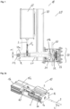
- Fig. 2a -d show perspective side views of a preferred embodiment of the triggering device 10 in different operating states.
- the triggering device 10 comprises a support frame 1 with a first end section 1a and a second end section 1b opposite it.
- An axially movable slide element is movably mounted in the support frame 1 as a triggering element 2, wherein the triggering rod 3 arranged on the end of the triggering element 2 extends through the end section 1a of the support frame 1.
- the end section 1a has a bore 1c as an axial bearing for the triggering rod 3.
- the slide element 2 can be moved at least between a release-ready holding position H ( Fig. 2a ) and a triggered position A ( Fig. 2b,2c ). Between the end section 1a and the trigger element 2, laterally arranged spring means 4a, 4b are provided, which apply a prestressing force to the slide element 2, which is oriented in a direction opposite to an extension direction of the trigger rod 3.
- the movable carriage element 2 is held by holding means 6a, 6b, which are arranged between the end section 1a of the support frame 1 and the carriage element 2.
- the holding means 6a, 6b are designed as electrically controllable magnets or as electromagnets, which, when supplied with current, cause a magnetic force on the carriage element 2, counter to the applied preload force of the spring means 4a, 4b. At least in the holding position H, this magnetic force is higher than the force of the spring means 4a, 4b.
- the holding means 6a, 6b are de-energized, whereby the carriage element 2 is released from the Fig. 2a shown holding position H to the in Fig. 2b shown triggered position A.
- the triggered position is preferably not limited by a rear stop in the support frame. This means that the support frame 1 is preferably designed in such a way that sufficient axial movement space is provided for the trigger or slide element 2 for a safe triggering and the associated necessary stroke.
- the triggering device 10 in this embodiment comprises a tensioning slide 15 that is axially movable independently of the trigger element 2.
- This has a first end section 15a in which the magnetically acting holding means 6a, 6b are arranged.
- the end section 15a also has a recess or a bore 23 for contact-free passage of the trigger rod 3.
- a second, opposite end section 15b is preferably connected to drive means such as a spindle motor 15c.
- the tensioning slide 15 is mounted axially movable parallel to the slide element 2 in the support frame 1 and is designed in such a way that the trigger element 2 can be moved from a triggered position A as in Fig. 2b shown to return to the holding position H.
- the clamping slide 15 is moved by an associated control unit from the initial end position in the support frame as in Fig. 2a shown towards the trigger element 2 in the triggered position by the drive means 15c (see intermediate position Fig. 2b ), preferably until the holding means 6a, 6b of the clamping slide 15 touch the trigger element 2 or are at least adjacent to it (cf. Fig. 2c,2d).
- Fig. 2d shows a rear view of the triggering device 10, wherein the triggering element 2 is in the triggered position and the tensioning slide 15 is in the extended position or in contact with the triggering element 2.
- the holding means 6a, 6b are then supplied with power so that a magnetic force acts on the release means.
- the tensioning carriage 15 is then brought back into the initial end position in the support frame 1 by the drive means 15c, whereby the applied magnetic force pulls the release unit 2 along and brings it into its holding position, as shown in Fig. 2a shown.
- the tensioning carriage 15 always moves on a side of the trigger unit 2 facing the trigger rod 3, and an area to the rear is not blocked or adjusted by the tensioning carriage. This means that the correct operation of the trigger device can always be guaranteed even if the trigger unit is reset.
- the triggering device 10 can preferably provide continuous position detection of the axially movable triggering element 2 and/or the axially movable clamping slide 15 in the support frame 1 by means of position detection means 17 provided for this purpose.
- the position detection means can comprise a plurality of sensors 17a arranged in or on the support frame 1 or on the housing 60, preferably in series, for example Hall sensors, as shown by way of example in Fig. 2c
- the Hall sensors can detect, for example, magnetically detectable and/or evaluable tags 17b arranged on the trigger element 2 and/or on the clamping slide 15 and thereby determine the respective position of the component along the possible axial range of motion.
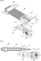
- Fig. 3 shows a perspective side view of another preferred embodiment of the triggering device 10, wherein the housing 60 has been omitted for reasons of clarity.
- Fig. 3 shows an embodiment in which the magnetically acting holding means comprise two coil bodies 5a, 5b arranged in a fixed position and opposite one another in the support frame 1, wherein Fig. 3 the front coil body is shown cut off for reasons of clarity.
- Both coil bodies 5a, 5b are aligned parallel to one another and preferably extend over the entire length of the support frame 1.
- the trigger element 2 is arranged between the coil bodies 5a, 5b, on which at least one permanent magnet 16 is arranged.
- the coil bodies 5a, 5b and the magnet 16 are arranged and designed in such a way that the coil bodies 5a, 5b enable an axial movement of the trigger element 2 in the direction opposite to the prestressing force of the spring means 4a, 4b and a holding of the trigger element 2 in a holding position H when current is supplied.
- the in Fig. 3 The position shown corresponds to a triggered position of the trigger element 2.
- the coil bodies 5a, 5b are supplied with current so that the trigger element 2 moves in the direction of the end section 1a of the support frame 1 (axial movement F2).
- the trigger element 2 can then be held in the holding position against the preload force of the springs 4a, 4b.
- the device can have at least one or two electrically controllable magnets 5c, 5d, which are arranged on the end section 1a of the support frame 1 and which can alternatively or additionally be energized in order to hold the trigger element 2 in the holding position.
- Fig . 4a ,b show a preferred embodiment of the trigger or slide element 2 according to the invention for the device as in Fig. 2a-2d
- the carriage element 2 is preferably designed as frame-like slide element which has two guide strips 7a, 7b extending in the axial direction of movement for guiding the slide element 2 in the support frame 1 and a connecting strip 8a aligned orthogonally thereto for supporting the trigger rod 3.
- the guide strips 7a, 7b extend from the connecting strip 8a in a direction L1 opposite to an extension direction L2 of the trigger rod 3.
- a rear frame strip 8b is arranged parallel to the connecting strip 8a.
- the slide element 2 is preferably designed as a plugged frame element in which the individual frame strips 7a, 7b, 8a, 8b are plugged into one another by means of projections, recesses and/or recesses provided.
- the guide strips 7a, 7b of the slide element 2 can, for example, each have recesses 12a, 12b arranged opposite one another, into which projections 13a, 13b of the connecting strip 8a and the rear frame strip 8b engage.
- the connecting strip 8a comprises an integrated bearing element 9 in which an end section 3a of the trigger rod 3 is preferably mounted so as to be at least partially rotatable, radially displaceable and/or tiltable.
- the bearing element 9 can be designed as a recess in the connecting strip 8a, which engages in a preferably circumferential groove 11 of a lateral surface of the end section 3a of the trigger rod 3.
- the bearing element 9 can also have a recess with a variable inner diameter, wherein a first region 9a of the recess has an inner diameter for receiving and passing through the trigger rod 3 and a second region 9b of the recess has a reduced inner diameter for axially fixed mounting of the trigger rod 3.
- the trigger rod 3 can be held in the region 9b after being inserted into the bearing element 9 by means of a correspondingly provided securing element 9c.
- the guide rails 7a, 7b and/or a rear frame rail 8b can have laterally projecting stop elements 14a, 14b against which the spring means 4a, 4b rest.
- Fig. 5a ,b show a second preferred embodiment of the carriage unit 2 according to the invention for the device as in Fig. 3
- the slide element is similar to the element according to Fig. 4a,4b constructed, but has at least one permanent magnet 16 in a central region, which is designed to interact with the coil bodies 5a, 5b of the holding means.
- the bearing element 9 in this embodiment can comprise a bore into which the end section 3a of the trigger rod 3 can be inserted.
- the securing element 9c can be a two-part cover element which can be selectively fastened to the connecting strip 8a in such a way that two opposing, for example semicircular, recesses engage in a groove 11 of a lateral surface of the end section 3a of the trigger rod 3.
- Fig. 6 shows a detailed view of a preferred connection of the triggering device 10 with a braking unit 30 of the safety gear 20.
- the triggering rod 3 can have a slotted hole 24 extending in the direction of movement at the connection point with the engagement lever 21, in which a bolt 24a of the engagement lever 21 is at least partially movably mounted.
- the elongated hole 24 can be arranged in such a way that in a holding position of the triggering device 10 the bolt 24a rests against a lower end stop of the elongated hole 24, so that a triggering of the triggering element 10 leads directly to the transmission of force to the engagement lever 21.
- the triggering rod 3 can be at least partially pushed through the elongated hole 24. be moved independently of the engagement lever 21.
- the movement possibility of the bolt 24a in the elongated hole 24 can be adjusted by means of a spring element 25 assigned to the release device 10 and an associated adjusting screw 26.
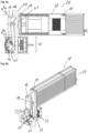
- Fig. 7a -c show different views of another preferred embodiment of the safety device 20 according to the invention.
- the safety gear 20 is attached horizontally to an elevator car (not shown), either directly or with appropriate fastening means or a carrier unit 80.
- the safety gear 20 comprises a deflection unit 40, which is designed such that it converts an axial movement L of the release rod 3 into a rotation R1 of a connecting rod 22 of the safety gear 20 (cf. Fig. 7b,7c ).
- the connecting rod 22 is designed to connect at least two braking devices 30 to a single triggering device 10.
- the deflection unit 40 can have an L-shaped bearing element 41 which extends in the direction of the trigger rod 3 and orthogonally thereto and has at least one bearing point 42 for the rotational mounting of the connecting rod 22, such that the connecting rod 22 extends orthogonally to the longitudinal extent of the trigger rod 3.
- the deflection unit 40 also preferably has a lever element 43 which is rigidly connected to the connecting rod 22 and which converts an axial movement of the trigger rod 3 into a rotational movement of the connecting rod 22.
- the lever element 43 is articulated to the trigger rod 3.
- the connecting rod 22 can be, for example, a square profile, with which a respective engagement lever 21 of a braking device 30 can be directly connected at one end.
- the deflection unit 40 can Preferably, at least two braking devices or braking units 30 are connected to a single trigger unit 10.
- the embodiment of the Fig. 7 ac allows a particularly space-saving arrangement or implementation of the safety gear 20.
- the safety gear 20 can be arranged, preferably centrally, on the top and/or bottom of the elevator car (not shown).
- the deflection unit 40 creates a very space-saving arrangement of the safety gear 20 in the plane of a base area of the elevator car, for example parallel to the car floor, so that it can be implemented with an extremely small overhang over the base area of the elevator car even in very narrow elevator shafts or can be implemented in narrow elevator shafts without the base area of the elevator car being significantly reduced or further limited by the safety gear for a given geometry of the elevator shaft.
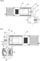
- Fig. 8a -c show different views of a preferred embodiment of the double-acting safety gear 20 according to the invention. This differs from the previously described embodiments in that it is designed to brake an elevator car 70 connected thereto in a first and a second direction of movement B1, B2 opposite thereto.
- the safety gear 20 comprises a triggering device 10, preferably as described above, which has a guide cage 18 arranged on the triggering rod 3 with a running surface 18a facing the triggering device 10 and a rotation element 19, in particular a knurled wheel, mounted therein for connection to an engagement lever 21 of the associated braking device 30.
- a guide rail 50 of the elevator or elevator car is arranged between the guide cage 18 and a housing 60 of the triggering device 10.
- the housing 60 of the triggering device 10 and the guide cage 18 enclose the Guide rail 50 in a sandwich-like manner.
- a sliding element 61 or counter-pressure element can be arranged on an end section 1a of the housing 60 of the triggering device 10.
- the guide cage 18 is preferably arranged in a fixed position on the trigger rod 3.
- the guide cage 18 is now moved in the direction of movement F3 towards the housing 60 of the trigger device 10, whereby the rotation element 19 presses against the guide rail 50 of the elevator and rolls along it.
- the running surface 18a can preferably be designed in such a way that it tapers up and down relative to the adjacent guide rail 50, whereby an increased contact pressure of the rotation element 19 on the guide rail 50 can be achieved.
- the movement of the rotary element 19 thus triggered perpendicular to the longitudinal extension of the triggering device 10 is transmitted to a brake unit 30 connected thereto by means of an engagement lever 21 fastened to the rotary element 19, whereby the pivotable brake shoe 31 connected thereto is pressed against the guide rail 50 around a joint 46 from top to bottom or from bottom to top, depending on the direction of movement of the rotary element 19, whereby a corresponding braking effect is achieved against the respective adjacent cabin movement.
- Fig. 9 shows a further preferred embodiment of the double-acting safety device 20 according to the invention. This is analogous to the embodiment according to Fig. 8a-c and differs essentially only in the design of the running surface 18a of the guide cage 18.
- the section 44 can be slightly concave.
- the running surface has two essentially concave recesses 45a, 45b into which the rotation element 19 is brought or runs when it comes into contact with the guide rail 50 and in doing so exerts a force essentially orthogonal to the axial movement of the trigger rod 3 on the engagement lever 21 and thus on the brake shoe 31.
Landscapes
- Engineering & Computer Science (AREA)
- Mechanical Engineering (AREA)
- Automation & Control Theory (AREA)
- Computer Networks & Wireless Communication (AREA)
- Maintenance And Inspection Apparatuses For Elevators (AREA)
Claims (15)
- Dispositif de déclenchement (10) pour un parachute (20) à prise instantanée d'une installation d'ascenseur, ledit dispositif de déclenchement (10) comprenant un cadre de support (1), un élément de déclenchement (2) disposé de manière axialement mobile dans le cadre de support et ayant une tige de déclenchement (3) qui est disposée d'un côté d'extrémité, qui s'étend à travers une partie d'extrémité (1a) du cadre de support (1) et qui sert à être reliée à un levier d'embrayage (21) du parachute (20) à prise instantanée, des moyens à ressort (4a, 4b) qui servent à appliquer une force de précontrainte sur l'élément de déclenchement (2) au moins dans une position de retenue (H), et des moyens de retenue (5a, 5b, 6a, 6b) à action magnétique qui sont conçus pour retenir l'élément de déclenchement (2), de préférence sous l'alimentation en électricité, dans la position de retenue (H) contre la force de précontrainte appliquée, caractérisé en ce que l'élément de déclenchement (2) est conçu comme élément de chariot, de préférence en forme de cadre, qui a deux barres de guidage (7a, 7b) qui s'étendent dans la direction de mouvement axiale et qui servent à guider l'élément de chariot (2) dans le cadre de support (1) et une barre de liaison (8a) qui est disposée perpendiculairement aux barres de guidage et relie celles-ci et qui sert à supporter la tige de déclenchement (3).
- Dispositif de déclenchement selon la revendication 1, caractérisé en ce que les barres de guidage (7a, 7b) s'étendent à partir de la barre de liaison (8a) dans une direction (L1) opposée à une direction de dimension (L2) de la tige de déclenchement (3).
- Dispositif de déclenchement selon la revendication 1 ou 2, caractérisé en ce que la barre de liaison (8a) a un élément de palier (9) intégré dans lequel une partie d'extrémité (3a) de la tige de déclenchement (3) est montée de manière à être rotative, déplaçable radialement et/ou capable de basculer, de préférence au moins partiellement.
- Dispositif de déclenchement selon l'une quelconque des revendications précédentes, caractérisé en ce que l'élément de chariot (2) a une barre de cadre (8b) arrière, qui est disposée parallèlement à la barre de liaison (8a), d'un côté détourné de la tige de déclenchement (3) et en ce que l'élément de chariot (2) est conçu comme élément de cadre emboîté dans lequel les barres de cadre (7a, 7b, 8a, 8b) individuelles sont emboîtées les unes dans les autres au moyen de saillies, d'épaulements et/ou d'évidements prévus.
- Dispositif de déclenchement selon l'une quelconque des revendications précédentes, caractérisé en ce que les moyens à ressort du dispositif de déclenchement comprennent deux ressort de compression (4a, 4b) qui s'étendent latéralement de l'élément de chariot en forme de cadre et qui s'étendent, de préférence, entre une partie d'extrémité (1a) du cadre de support orientée vers la tige de déclenchement (3) et une partie d'extrémité (2b) de l'élément de chariot (2) détournée de la tige de déclenchement (3).
- Dispositif de déclenchement selon la revendication 5, caractérisé en ce que les barres de guidage (7a, 7b) et/ou une barre de cadre (8b) arrière ont des éléments d'arrêt (14a, 14b) qui font saillie latéralement pour les moyens à ressort (4a, 4b).
- Dispositif de déclenchement selon l'une quelconque des revendications précédentes, caractérisé en ce que les moyens de retenue à action magnétique comprennent, de préférence, deux électroaimants (6a, 6b) qui sont disposés entre l'élément de déclenchement (2) et une partie d'extrémité (1a) du cadre de support à travers laquelle s'étend la tige de déclenchement (3) et qui appliquent, sous l'alimentation en électricité, une force de retenue sur l'élément de chariot (2), et notamment la barre de liaison (8a) de l'élément de chariot (2).
- Dispositif de déclenchement selon la revendication 7, caractérisé en ce que le dispositif de déclenchent (10) comprend un chariot de serrage (15) qui est mobile axialement de manière indépendante par rapport à l'élément de déclenchement (2) et qui a une partie d'extrémité (15a) dans laquelle les moyens de retenue (6a, 6b) à action magnétique sont disposés, et dans lequel le chariot de serrage (15) est conçu pour ramener l'élément de déclenchement (2) sous l'interaction avec les moyens de retenue (6a, 6b) à action magnétique d'une position déclenchée (A) dans la position de retenue (H).
- Dispositif de déclenchement selon l'une quelconque des revendications 1 à 6, caractérisé en ce que les moyens de retenue à action magnétique comprennent, de préférence, deux corps de bobine (5a, 5b) qui sont disposés de manière fixée en position et opposée dans le cadre de support (1), qui servent à interagir avec un aimant permanent (16) disposé sur l'élément de déclenchement (2) de manière à se trouver entre eux, et qui sont disposés et conçus de telle manière que les corps de bobine (5a, 5b) permettent, sous l'alimentation en électricité, un mouvement axial de l'élément de déclenchement (2) dans la direction contre la force de précontrainte des moyens à ressort (4a, 4b) et une rétention de l'élément de déclenchement (2) dans la position de retenu (H).
- Dispositif de déclenchement selon l'une quelconque des revendications précédentes, caractérisé en ce que le dispositif de déclenchement (10) a des moyens (17) de détection de position qui permettent une détection de position continue de l'élément de déclenchement (2) axialement mobile et/ou d'un chariot de serrage (15) axialement mobile dans le cadre de support (1).
- Parachute (20) à prise instantanée comprenant un dispositif de freinage (30) guidé dans et/ou sur un rail de guidage (50) d'une cabine d'ascenseur et un levier d'embrayage (21), qui est relié audit dispositif de freinage (30), qui est, de préférence partiellement, rotatif et qui sert à déclencher sélectivement le dispositif de freinage (30), et un dispositif de déclenchement (10) selon l'une quelconque des revendications 1 à 10 relié au levier d'embrayage (21).
- Parachute à prise instantanée selon la revendication 11, caractérisé en ce que le parachute à prise instantanée comprend une unité de déviation (40) qui est conçue pour convertir un mouvement axial (L) de la tige de déclenchement (3) en une rotation (R) d'une tige de liaison (22) du parachute (20) à prise instantanée, dans lequel la tige de liaison (22) est conçue pour relier au moins deux dispositifs de freinage (30) au dispositif de déclenchement (10).
- Parachute à prise instantanée selon la revendication 11, caractérisé en ce que le dispositif de déclenchement (10) a une cage de guidage (18), qui est disposée sur la tige de déclenchement (3) et qui a une surface de roulement (18a) orientée vers le dispositif de déclenchement (10), et un élément de rotation (19), notamment une molette, qui est monté dans ladite cage de guidage (18) et qui sert à être relié à un levier d'embrayage (21) du dispositif de freinage (30), dans lequel l'élément de rotation (19) et la cage de guidage (18) sont disposés et conçus de manière qu'un rail de guidage (50) de l'ascenseur est capable d'être disposé entre la surface de roulement (18a) et une partie d'extrémité (1a) du cadre de support (1) du dispositif de déclenchement (10).
- Parachute à prise instantanée selon la revendication 13, caractérisé en ce que l'élément de rotation (19) et la cage de guidage (18) sont disposés et conçus de manière que l'élément de rotation (19) presse contre un rail de guidage (50) de l'ascenseur lorsque le dispositif de déclenchement (10) est déclenché et roule sur ledit rail de guidage (50) dans une direction essentiellement orthogonale à une direction de dimension (L) de la tige de déclenchement (3) et/ou que l'élément de rotation (19) coince entre la surface de roulement (18a) et le rail de guidage (50).
- Parachute à prise instantanée selon la revendication 13 ou 14, caractérisé en ce que le parachute (20) à prise instantanée est conçu pour freiner une cabine d'ascenseur reliée avec celui-ci dans une première et une deuxième direction de mouvement (B1, B2), ladite deuxième direction de mouvement étant opposée à la première direction de mouvement.
Priority Applications (3)
| Application Number | Priority Date | Filing Date | Title |
|---|---|---|---|
| EP22158353.7A EP4234470B1 (fr) | 2022-02-23 | 2022-02-23 | Unité de déclenchement pour un dispositif de capture |
| US18/113,508 US12338102B2 (en) | 2022-02-23 | 2023-02-23 | Safety gear for an elevator system |
| CN202310155305.9A CN116639567A (zh) | 2022-02-23 | 2023-02-23 | 用于防坠装置的触发装置 |
Applications Claiming Priority (1)
| Application Number | Priority Date | Filing Date | Title |
|---|---|---|---|
| EP22158353.7A EP4234470B1 (fr) | 2022-02-23 | 2022-02-23 | Unité de déclenchement pour un dispositif de capture |
Publications (3)
| Publication Number | Publication Date |
|---|---|
| EP4234470A1 EP4234470A1 (fr) | 2023-08-30 |
| EP4234470B1 true EP4234470B1 (fr) | 2024-12-25 |
| EP4234470C0 EP4234470C0 (fr) | 2024-12-25 |
Family
ID=80448726
Family Applications (1)
| Application Number | Title | Priority Date | Filing Date |
|---|---|---|---|
| EP22158353.7A Active EP4234470B1 (fr) | 2022-02-23 | 2022-02-23 | Unité de déclenchement pour un dispositif de capture |
Country Status (3)
| Country | Link |
|---|---|
| US (1) | US12338102B2 (fr) |
| EP (1) | EP4234470B1 (fr) |
| CN (1) | CN116639567A (fr) |
Family Cites Families (15)
| Publication number | Priority date | Publication date | Assignee | Title |
|---|---|---|---|---|
| US4102444A (en) * | 1976-12-16 | 1978-07-25 | Wehr Corporation | Stepped torque rotary motion brake |
| JPH10184844A (ja) * | 1996-12-25 | 1998-07-14 | Smc Corp | 電動アクチュエータ |
| ES2614438T3 (es) * | 2009-03-16 | 2017-05-31 | Otis Elevator Company | Activador electromagnético de seguridad |
| TWI499731B (zh) * | 2013-01-17 | 2015-09-11 | Timotion Technology Co Ltd | 線性傳動裝置改良 |
| EP2837592A1 (fr) * | 2013-08-13 | 2015-02-18 | Aplicaciones Electromecanicas Gervall, S.A. | Système d'entraînement destiné à un engrenage de sécurité d'ascenseur |
| DE102013111385A1 (de) * | 2013-10-15 | 2015-04-16 | Manfred Lienemann | Auslösevorrichtung einer Fangvorrichtung für eine Aufzugskabine einer Aufzugsanlage |
| US10584014B2 (en) * | 2015-12-07 | 2020-03-10 | Otis Elevator Company | Robust electrical safety actuation module |
| US10889468B2 (en) * | 2016-12-13 | 2021-01-12 | Otis Elevator Company | Electronics safety actuator |
| CN109516336B (zh) | 2018-12-29 | 2024-09-13 | 刘英辉 | 直线驱动装置、安全钳装置及电梯系统的控制方法 |
| EP3677534B1 (fr) * | 2019-01-02 | 2021-07-21 | Otis Elevator Company | Actioneur d'un dispositif de sécurité d'ascenseur |
| DE202019103423U1 (de) * | 2019-06-18 | 2019-06-28 | Wittur Holding Gmbh | Bremsvorrichtung mit automatischer Lüftbarkeit in sämtlichen Betriebsfällen |
| DE202019105584U1 (de) * | 2019-10-10 | 2019-10-22 | Wittur Holding Gmbh | Auslöseeinheit zum Betätigen einer Aufzugbremsvorrichtung |
| US12234125B2 (en) * | 2020-02-14 | 2025-02-25 | Wittur Holding Gmbh | Triggering unit for actuating an elevator braking device |
| CN111362093B (zh) * | 2020-04-27 | 2024-05-24 | 重庆迈高电梯有限公司 | 一种电梯安全钳提拉机构及电梯 |
| CN111731964B (zh) | 2020-07-24 | 2025-05-13 | 刘英辉 | 安全钳提拉装置、电梯轿厢及其使用方法 |
-
2022
- 2022-02-23 EP EP22158353.7A patent/EP4234470B1/fr active Active
-
2023
- 2023-02-23 US US18/113,508 patent/US12338102B2/en active Active
- 2023-02-23 CN CN202310155305.9A patent/CN116639567A/zh active Pending
Also Published As
| Publication number | Publication date |
|---|---|
| EP4234470A1 (fr) | 2023-08-30 |
| CN116639567A (zh) | 2023-08-25 |
| US12338102B2 (en) | 2025-06-24 |
| US20230286779A1 (en) | 2023-09-14 |
| EP4234470C0 (fr) | 2024-12-25 |
Similar Documents
| Publication | Publication Date | Title |
|---|---|---|
| EP2925654B1 (fr) | Dispositif antichute pour un corps mobile d'une installation de levage | |
| EP1213247B1 (fr) | Installation et méthode pour débloquer un frein de secours | |
| DE69509265T2 (de) | Vorrichtung in einem Aufzugsübergeschwindigkeitsbegrenzer | |
| EP2931641B1 (fr) | Dispositif antichute pour une installation d'ascenseur | |
| EP3197812B1 (fr) | Frein d'ascenseur | |
| DE60003262T2 (de) | Bremsvorrichtung mit Bremsnachstellungsvorrichtung | |
| EP3538468B1 (fr) | Frein à câble, cabine d'ascenseur et ascenseur | |
| DE102013111385A1 (de) | Auslösevorrichtung einer Fangvorrichtung für eine Aufzugskabine einer Aufzugsanlage | |
| EP3938308B1 (fr) | Frein de sécurité et procédé de freinage | |
| DE102008007094A1 (de) | Verriegelungsvorrichtung für eine längs- und/oder neigungsverstellbare Lenksäule eines Kraftfahrzeuges | |
| EP1646575A1 (fr) | Frein de cable | |
| EP4080102B1 (fr) | Interrupteur de sécurité à gâchette | |
| DE102022103978A1 (de) | Elektromotorische Aktorbaugruppe für eine elektromechanische Fahrzeugbremse und Verfahren zum Aktivieren und Deaktivieren einer Parkbremsfunktion | |
| EP4061757B1 (fr) | Parachute électronique à réarmement aisé | |
| EP1400476A1 (fr) | Parachute pour ascenseurs | |
| EP4234470B1 (fr) | Unité de déclenchement pour un dispositif de capture | |
| EP4077190B1 (fr) | Dispositif d'arrêt pour un ascenseur | |
| DE102009040109A1 (de) | Geschwindigkeitsbegrenzer für ein Aufzugsystem | |
| DE19533153C2 (de) | Schiebetür mit Notöffnungs- oder Notschließeinrichtung | |
| EP0992701B1 (fr) | Frein à tambour pour automobile | |
| EP3774629A1 (fr) | Frein à mâchoires pour un système d'ascenseur, qui fait office en particulier de frein de maintien et de sécurité | |
| WO2006000537A1 (fr) | Dispositif de verrouillage et / ou de deverrouillage du volant d'un vehicule a moteur | |
| EP3927641B1 (fr) | Système de déclenchement pour un dispositif d'arrêt, installation d'ascenseur et procédé pour faire fonctionner une installation d'ascenseur | |
| EP2050706B1 (fr) | Dispositif de fixation | |
| EP3458664A1 (fr) | Dispositif destiné à freiner le mouvement d'un systrème de fermeture |
Legal Events
| Date | Code | Title | Description |
|---|---|---|---|
| PUAI | Public reference made under article 153(3) epc to a published international application that has entered the european phase |
Free format text: ORIGINAL CODE: 0009012 |
|
| STAA | Information on the status of an ep patent application or granted ep patent |
Free format text: STATUS: THE APPLICATION HAS BEEN PUBLISHED |
|
| AK | Designated contracting states |
Kind code of ref document: A1 Designated state(s): AL AT BE BG CH CY CZ DE DK EE ES FI FR GB GR HR HU IE IS IT LI LT LU LV MC MK MT NL NO PL PT RO RS SE SI SK SM TR |
|
| STAA | Information on the status of an ep patent application or granted ep patent |
Free format text: STATUS: REQUEST FOR EXAMINATION WAS MADE |
|
| 17P | Request for examination filed |
Effective date: 20240226 |
|
| RBV | Designated contracting states (corrected) |
Designated state(s): AL AT BE BG CH CY CZ DE DK EE ES FI FR GB GR HR HU IE IS IT LI LT LU LV MC MK MT NL NO PL PT RO RS SE SI SK SM TR |
|
| GRAP | Despatch of communication of intention to grant a patent |
Free format text: ORIGINAL CODE: EPIDOSNIGR1 |
|
| STAA | Information on the status of an ep patent application or granted ep patent |
Free format text: STATUS: GRANT OF PATENT IS INTENDED |
|
| INTG | Intention to grant announced |
Effective date: 20240726 |
|
| RAP3 | Party data changed (applicant data changed or rights of an application transferred) |
Owner name: COBIANCHI LIFTTEILE AG Owner name: ELGO BATSCALE AG |
|
| GRAS | Grant fee paid |
Free format text: ORIGINAL CODE: EPIDOSNIGR3 |
|
| GRAA | (expected) grant |
Free format text: ORIGINAL CODE: 0009210 |
|
| STAA | Information on the status of an ep patent application or granted ep patent |
Free format text: STATUS: THE PATENT HAS BEEN GRANTED |
|
| AK | Designated contracting states |
Kind code of ref document: B1 Designated state(s): AL AT BE BG CH CY CZ DE DK EE ES FI FR GB GR HR HU IE IS IT LI LT LU LV MC MK MT NL NO PL PT RO RS SE SI SK SM TR |
|
| REG | Reference to a national code |
Ref country code: GB Ref legal event code: FG4D Free format text: NOT ENGLISH |
|
| REG | Reference to a national code |
Ref country code: CH Ref legal event code: EP |
|
| REG | Reference to a national code |
Ref country code: DE Ref legal event code: R096 Ref document number: 502022002468 Country of ref document: DE |
|
| REG | Reference to a national code |
Ref country code: IE Ref legal event code: FG4D Free format text: LANGUAGE OF EP DOCUMENT: GERMAN |
|
| U01 | Request for unitary effect filed |
Effective date: 20250123 |
|
| U07 | Unitary effect registered |
Designated state(s): AT BE BG DE DK EE FI FR IT LT LU LV MT NL PT RO SE SI Effective date: 20250218 |
|
| PG25 | Lapsed in a contracting state [announced via postgrant information from national office to epo] |
Ref country code: HR Free format text: LAPSE BECAUSE OF FAILURE TO SUBMIT A TRANSLATION OF THE DESCRIPTION OR TO PAY THE FEE WITHIN THE PRESCRIBED TIME-LIMIT Effective date: 20241225 |
|
| PG25 | Lapsed in a contracting state [announced via postgrant information from national office to epo] |
Ref country code: NO Free format text: LAPSE BECAUSE OF FAILURE TO SUBMIT A TRANSLATION OF THE DESCRIPTION OR TO PAY THE FEE WITHIN THE PRESCRIBED TIME-LIMIT Effective date: 20250325 |
|
| PG25 | Lapsed in a contracting state [announced via postgrant information from national office to epo] |
Ref country code: GR Free format text: LAPSE BECAUSE OF FAILURE TO SUBMIT A TRANSLATION OF THE DESCRIPTION OR TO PAY THE FEE WITHIN THE PRESCRIBED TIME-LIMIT Effective date: 20250326 |
|
| PGFP | Annual fee paid to national office [announced via postgrant information from national office to epo] |
Ref country code: CH Payment date: 20250325 Year of fee payment: 4 |
|
| PG25 | Lapsed in a contracting state [announced via postgrant information from national office to epo] |
Ref country code: RS Free format text: LAPSE BECAUSE OF FAILURE TO SUBMIT A TRANSLATION OF THE DESCRIPTION OR TO PAY THE FEE WITHIN THE PRESCRIBED TIME-LIMIT Effective date: 20250325 |
|
| U20 | Renewal fee for the european patent with unitary effect paid |
Year of fee payment: 4 Effective date: 20250325 |
|
| PG25 | Lapsed in a contracting state [announced via postgrant information from national office to epo] |
Ref country code: SM Free format text: LAPSE BECAUSE OF FAILURE TO SUBMIT A TRANSLATION OF THE DESCRIPTION OR TO PAY THE FEE WITHIN THE PRESCRIBED TIME-LIMIT Effective date: 20241225 |
|
| PG25 | Lapsed in a contracting state [announced via postgrant information from national office to epo] |
Ref country code: PL Free format text: LAPSE BECAUSE OF FAILURE TO SUBMIT A TRANSLATION OF THE DESCRIPTION OR TO PAY THE FEE WITHIN THE PRESCRIBED TIME-LIMIT Effective date: 20241225 |
|
| PG25 | Lapsed in a contracting state [announced via postgrant information from national office to epo] |
Ref country code: ES Free format text: LAPSE BECAUSE OF FAILURE TO SUBMIT A TRANSLATION OF THE DESCRIPTION OR TO PAY THE FEE WITHIN THE PRESCRIBED TIME-LIMIT Effective date: 20241225 |
|
| PG25 | Lapsed in a contracting state [announced via postgrant information from national office to epo] |
Ref country code: IS Free format text: LAPSE BECAUSE OF FAILURE TO SUBMIT A TRANSLATION OF THE DESCRIPTION OR TO PAY THE FEE WITHIN THE PRESCRIBED TIME-LIMIT Effective date: 20250425 |
|
| PG25 | Lapsed in a contracting state [announced via postgrant information from national office to epo] |
Ref country code: SK Free format text: LAPSE BECAUSE OF FAILURE TO SUBMIT A TRANSLATION OF THE DESCRIPTION OR TO PAY THE FEE WITHIN THE PRESCRIBED TIME-LIMIT Effective date: 20241225 |
|
| PG25 | Lapsed in a contracting state [announced via postgrant information from national office to epo] |
Ref country code: CZ Free format text: LAPSE BECAUSE OF FAILURE TO SUBMIT A TRANSLATION OF THE DESCRIPTION OR TO PAY THE FEE WITHIN THE PRESCRIBED TIME-LIMIT Effective date: 20241225 |
|
| PG25 | Lapsed in a contracting state [announced via postgrant information from national office to epo] |
Ref country code: MC Free format text: LAPSE BECAUSE OF FAILURE TO SUBMIT A TRANSLATION OF THE DESCRIPTION OR TO PAY THE FEE WITHIN THE PRESCRIBED TIME-LIMIT Effective date: 20241225 |
|
| PLBE | No opposition filed within time limit |
Free format text: ORIGINAL CODE: 0009261 |
|
| STAA | Information on the status of an ep patent application or granted ep patent |
Free format text: STATUS: NO OPPOSITION FILED WITHIN TIME LIMIT |
|
| REG | Reference to a national code |
Ref country code: CH Ref legal event code: L10 Free format text: ST27 STATUS EVENT CODE: U-0-0-L10-L00 (AS PROVIDED BY THE NATIONAL OFFICE) Effective date: 20251105 |
|
| 26N | No opposition filed |
Effective date: 20250926 |
|
| PG25 | Lapsed in a contracting state [announced via postgrant information from national office to epo] |
Ref country code: IE Free format text: LAPSE BECAUSE OF NON-PAYMENT OF DUE FEES Effective date: 20250223 |
|
| REG | Reference to a national code |
Ref country code: CH Ref legal event code: U11 Free format text: ST27 STATUS EVENT CODE: U-0-0-U10-U11 (AS PROVIDED BY THE NATIONAL OFFICE) Effective date: 20260301 |
|
| U20 | Renewal fee for the european patent with unitary effect paid |
Year of fee payment: 5 Effective date: 20260226 |