EP4243215A1 - Connecteur - Google Patents
Connecteur Download PDFInfo
- Publication number
- EP4243215A1 EP4243215A1 EP23159791.5A EP23159791A EP4243215A1 EP 4243215 A1 EP4243215 A1 EP 4243215A1 EP 23159791 A EP23159791 A EP 23159791A EP 4243215 A1 EP4243215 A1 EP 4243215A1
- Authority
- EP
- European Patent Office
- Prior art keywords
- connector
- ground terminal
- terminal part
- casing
- fitting part
- Prior art date
- Legal status (The legal status is an assumption and is not a legal conclusion. Google has not performed a legal analysis and makes no representation as to the accuracy of the status listed.)
- Pending
Links
Images


Classifications
-
- H—ELECTRICITY
- H01—ELECTRIC ELEMENTS
- H01R—ELECTRICALLY-CONDUCTIVE CONNECTIONS; STRUCTURAL ASSOCIATIONS OF A PLURALITY OF MUTUALLY-INSULATED ELECTRICAL CONNECTING ELEMENTS; COUPLING DEVICES; CURRENT COLLECTORS
- H01R24/00—Two-part coupling devices, or either of their cooperating parts, characterised by their overall structure
- H01R24/38—Two-part coupling devices, or either of their cooperating parts, characterised by their overall structure having concentrically or coaxially arranged contacts
- H01R24/40—Two-part coupling devices, or either of their cooperating parts, characterised by their overall structure having concentrically or coaxially arranged contacts specially adapted for high frequency
- H01R24/54—Intermediate parts, e.g. adapters, splitters or elbows
- H01R24/542—Adapters
-
- H—ELECTRICITY
- H01—ELECTRIC ELEMENTS
- H01R—ELECTRICALLY-CONDUCTIVE CONNECTIONS; STRUCTURAL ASSOCIATIONS OF A PLURALITY OF MUTUALLY-INSULATED ELECTRICAL CONNECTING ELEMENTS; COUPLING DEVICES; CURRENT COLLECTORS
- H01R12/00—Structural associations of a plurality of mutually-insulated electrical connecting elements, specially adapted for printed circuits, e.g. printed circuit boards [PCB], flat or ribbon cables, or like generally planar structures, e.g. terminal strips, terminal blocks; Coupling devices specially adapted for printed circuits, flat or ribbon cables, or like generally planar structures; Terminals specially adapted for contact with, or insertion into, printed circuits, flat or ribbon cables, or like generally planar structures
- H01R12/70—Coupling devices
- H01R12/71—Coupling devices for rigid printing circuits or like structures
- H01R12/75—Coupling devices for rigid printing circuits or like structures connecting to cables except for flat or ribbon cables
-
- H—ELECTRICITY
- H01—ELECTRIC ELEMENTS
- H01R—ELECTRICALLY-CONDUCTIVE CONNECTIONS; STRUCTURAL ASSOCIATIONS OF A PLURALITY OF MUTUALLY-INSULATED ELECTRICAL CONNECTING ELEMENTS; COUPLING DEVICES; CURRENT COLLECTORS
- H01R13/00—Details of coupling devices of the kinds covered by groups H01R12/70 or H01R24/00 - H01R33/00
- H01R13/40—Securing contact members in or to a base or case; Insulating of contact members
-
- H—ELECTRICITY
- H01—ELECTRIC ELEMENTS
- H01R—ELECTRICALLY-CONDUCTIVE CONNECTIONS; STRUCTURAL ASSOCIATIONS OF A PLURALITY OF MUTUALLY-INSULATED ELECTRICAL CONNECTING ELEMENTS; COUPLING DEVICES; CURRENT COLLECTORS
- H01R13/00—Details of coupling devices of the kinds covered by groups H01R12/70 or H01R24/00 - H01R33/00
- H01R13/46—Bases; Cases
- H01R13/502—Bases; Cases composed of different pieces
-
- H—ELECTRICITY
- H01—ELECTRIC ELEMENTS
- H01R—ELECTRICALLY-CONDUCTIVE CONNECTIONS; STRUCTURAL ASSOCIATIONS OF A PLURALITY OF MUTUALLY-INSULATED ELECTRICAL CONNECTING ELEMENTS; COUPLING DEVICES; CURRENT COLLECTORS
- H01R13/00—Details of coupling devices of the kinds covered by groups H01R12/70 or H01R24/00 - H01R33/00
- H01R13/648—Protective earth or shield arrangements on coupling devices, e.g. anti-static shielding
- H01R13/652—Protective earth or shield arrangements on coupling devices, e.g. anti-static shielding with earth pin, blade or socket
-
- H—ELECTRICITY
- H01—ELECTRIC ELEMENTS
- H01R—ELECTRICALLY-CONDUCTIVE CONNECTIONS; STRUCTURAL ASSOCIATIONS OF A PLURALITY OF MUTUALLY-INSULATED ELECTRICAL CONNECTING ELEMENTS; COUPLING DEVICES; CURRENT COLLECTORS
- H01R13/00—Details of coupling devices of the kinds covered by groups H01R12/70 or H01R24/00 - H01R33/00
- H01R13/648—Protective earth or shield arrangements on coupling devices, e.g. anti-static shielding
- H01R13/658—High frequency shielding arrangements, e.g. against EMI [Electro-Magnetic Interference] or EMP [Electro-Magnetic Pulse]
- H01R13/6591—Specific features or arrangements of connection of shield to conductive members
- H01R13/6594—Specific features or arrangements of connection of shield to conductive members the shield being mounted on a PCB and connected to conductive members
-
- H—ELECTRICITY
- H01—ELECTRIC ELEMENTS
- H01R—ELECTRICALLY-CONDUCTIVE CONNECTIONS; STRUCTURAL ASSOCIATIONS OF A PLURALITY OF MUTUALLY-INSULATED ELECTRICAL CONNECTING ELEMENTS; COUPLING DEVICES; CURRENT COLLECTORS
- H01R24/00—Two-part coupling devices, or either of their cooperating parts, characterised by their overall structure
- H01R24/38—Two-part coupling devices, or either of their cooperating parts, characterised by their overall structure having concentrically or coaxially arranged contacts
- H01R24/40—Two-part coupling devices, or either of their cooperating parts, characterised by their overall structure having concentrically or coaxially arranged contacts specially adapted for high frequency
- H01R24/52—Two-part coupling devices, or either of their cooperating parts, characterised by their overall structure having concentrically or coaxially arranged contacts specially adapted for high frequency mounted in or to a panel or structure
-
- H—ELECTRICITY
- H01—ELECTRIC ELEMENTS
- H01R—ELECTRICALLY-CONDUCTIVE CONNECTIONS; STRUCTURAL ASSOCIATIONS OF A PLURALITY OF MUTUALLY-INSULATED ELECTRICAL CONNECTING ELEMENTS; COUPLING DEVICES; CURRENT COLLECTORS
- H01R24/00—Two-part coupling devices, or either of their cooperating parts, characterised by their overall structure
- H01R24/38—Two-part coupling devices, or either of their cooperating parts, characterised by their overall structure having concentrically or coaxially arranged contacts
- H01R24/40—Two-part coupling devices, or either of their cooperating parts, characterised by their overall structure having concentrically or coaxially arranged contacts specially adapted for high frequency
- H01R24/54—Intermediate parts, e.g. adapters, splitters or elbows
- H01R24/545—Elbows
-
- H—ELECTRICITY
- H01—ELECTRIC ELEMENTS
- H01R—ELECTRICALLY-CONDUCTIVE CONNECTIONS; STRUCTURAL ASSOCIATIONS OF A PLURALITY OF MUTUALLY-INSULATED ELECTRICAL CONNECTING ELEMENTS; COUPLING DEVICES; CURRENT COLLECTORS
- H01R2103/00—Two poles
-
- H—ELECTRICITY
- H01—ELECTRIC ELEMENTS
- H01R—ELECTRICALLY-CONDUCTIVE CONNECTIONS; STRUCTURAL ASSOCIATIONS OF A PLURALITY OF MUTUALLY-INSULATED ELECTRICAL CONNECTING ELEMENTS; COUPLING DEVICES; CURRENT COLLECTORS
- H01R24/00—Two-part coupling devices, or either of their cooperating parts, characterised by their overall structure
- H01R24/38—Two-part coupling devices, or either of their cooperating parts, characterised by their overall structure having concentrically or coaxially arranged contacts
- H01R24/40—Two-part coupling devices, or either of their cooperating parts, characterised by their overall structure having concentrically or coaxially arranged contacts specially adapted for high frequency
- H01R24/50—Two-part coupling devices, or either of their cooperating parts, characterised by their overall structure having concentrically or coaxially arranged contacts specially adapted for high frequency mounted on a PCB [Printed Circuit Board]
-
- H—ELECTRICITY
- H04—ELECTRIC COMMUNICATION TECHNIQUE
- H04N—PICTORIAL COMMUNICATION, e.g. TELEVISION
- H04N23/00—Cameras or camera modules comprising electronic image sensors; Control thereof
- H04N23/50—Constructional details
- H04N23/51—Housings
-
- H—ELECTRICITY
- H04—ELECTRIC COMMUNICATION TECHNIQUE
- H04N—PICTORIAL COMMUNICATION, e.g. TELEVISION
- H04N23/00—Cameras or camera modules comprising electronic image sensors; Control thereof
- H04N23/57—Mechanical or electrical details of cameras or camera modules specially adapted for being embedded in other devices
Definitions
- the present invention relates to a connector.
- camera modules such as on-vehicle camera modules, for example, in which a substrate on which an imaging device such as a CCD sensor or a CMOS sensor is mounted and an optical device such as a lens are integrated, and a connector is used for connecting a cable such as a coaxial cable to such a camera module (for example, Japanese Patent Application Laid-Open No. 2019-133748 ).
- Japanese Patent Application Laid-Open No. 2019-133748 is an example of the related art.
- the connector disclosed in Japanese Patent Application Laid-Open No. 2019-133748 includes an outer conductor fitted into the connector provided to a substrate and is structured such that the outer conductor is joined to an outer conductor holding part by welding.
- the present invention intends to provide a connector that can achieve improvement in strength, improvement in shape accuracy, a reduction in the number of components, and a reduction in the number of steps required for assembly.
- a connector according to one aspect of the present invention is a connector for connecting an external substrate and an external cable to each other, and the connector includes: a metal casing having a ground terminal part and a fitting part, the ground terminal part being electrically connected to and fitted into an external substrate-side connector mounted to the substrate, and the fitting part into which the cable is fitted, and the ground terminal part and the fitting part are integrally formed.
- the connector since the connector includes the metal casing having the ground terminal part and the fitting part, the ground terminal part is electrically connected to and fitted into the substrate-side connector mounted to the substrate, and the fitting part into which the cable is fitted, and the ground terminal part and the fitting part are integrally formed, the strength as a connector can be improved compared to a case where the ground terminal part is joined (for example, welded) with the casing having the fitting part. Accordingly, when the ground terminal part of the connector is connected to (fitted into) the substrate-side connector, the possibility of damage to the connector being can be reduced.
- ground terminal part and the fitting part are integrally formed, no gap is formed between the ground terminal part and the fitting part and the ground is enhanced compared to a case where the ground terminal part is joined to the casing having the fitting part, and therefore, electrical performance is improved (signal transmission is stabilized). Further, the accuracy of the shape of the casing (such as the positional accuracy of the ground terminal part relative to the fitting part) is more reliably determined. Further, a reduction in the number of components or a reduction in the number of steps required for assembly can be achieved.
- the casing since the casing has a case part that accommodates the substrate, and the ground terminal part, the fitting part, and the case part are integrally formed, accuracy of the shape of the casing (positional accuracy of the ground terminal part relative to the fitting part, positional accuracy of the ground terminal part relative to the case part, or the like) is more reliably determined. Further, a reduction in the number of components or a reduction in the number of steps required for assembly can be achieved.
- the fitting part has a cylindrical shape extending along the first direction
- the ground terminal part has a cylindrical shape extending along the second direction
- the first direction and the second direction are parallel to each other
- the fitting part has a cylindrical shape extending along the first direction
- the ground terminal part has a cylindrical shape extending along the second direction
- the first direction and the second direction intersect each other
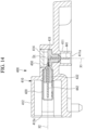
- the casing has an opening configured to be externally accessed at a position at which the first direction and the second direction intersect each other inside the casing and includes a cover member that closes the opening.
- the casing since the casing has the opening configured to be externally accessed at a position at which the first direction and the second direction intersect each other inside the casing and includes the cover member that closes the opening, the contact pin inserted from the fitting part along the first direction and the contact pin inserted from the ground terminal part along the second direction can be joined (for example, soldered) to each other inside the casing by operation via the opening.
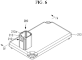
- a connector 100 is a relay connector to connect a substrate-side connector 521 mounted on a substrate 520 included in an on-vehicle camera module and an outer cable 600 to each other, for example.
- the substrate 520 is a substrate for driving an on-vehicle camera module, for example.
- the outer cable 600 is a FAKRA specification coaxial connector, for example.
- the substrate 520 is accommodated in a space defined by a camera case.
- the camera case is formed of a bottom camera case 510 and a top camera case (not illustrated), for example.
- An installation part 511 to which the connector 100 is attached is formed on the top face of the bottom camera case 510.
- the installation part 511 is a portion where a part of the top face of the bottom camera case 510 swells, and the installation part 511 has a through hole 512 and a threaded hole 513.
- the through hole 512 is a hole through which the outside of the bottom camera case 510 communicates with a space that accommodates the substrate 520.
- a ground terminal part 111 of the connector 100 described later is inserted in the through hole 512.
- the threaded hole 513 is a hole where an internal thread is formed in the inner circumference face.
- a fixing thread 530 for fixing the connector 100 to the bottom camera case 510 is screwed into the threaded hole 513.
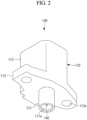
- the casing 110 has the ground terminal part 111, a fitting part 112, and a flange part 113.
- the ground terminal part 111 is a portion fitted into the outer circumference side of the substrate-side connector 521 and formed to a lower part of the casing 110.
- the fitting part 112 has a cylindrical shape extending along the direction of an axis X2, and the upper end thereof is formed as an opening 112a and has a space inside. A connector portion of the outer cable 600 is inserted from the opening 112a in the space.
- the shape of the fitting part 112 corresponds to the shape of the connector portion of the inserted outer cable 600.
- the contact pin 140 is a metal component having a long, thin linear shape.
- One end (upper end in Fig. 4 ) of the contact pin 140 protruding from the upper end face of the insulator 130 is located inside the outer conductor 120 and, when the outer cable 600 has been inserted in the fitting part 112, is connected to the outer cable 600. Accordingly, the contact pin 140 is electrically connected to the outer cable 600.
- the strength as the connector 100 can be improved compared to a case where the ground terminal part is joined (for example, welded) to the casing having a fitting part.
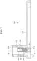
- the outer conductor 320 is a metal component having a cylindrical shape.
- the first insulator 331 is a component having a cylindrical shape and made of an insulating material having expanded diameter at the upper part.
- the first insulator 331 is pressed into the inside of the ground terminal part 311 along the direction of the axis X1. Accordingly, the first insulator 331 is fixed to the ground terminal part 311.
- the second insulator 332 is a component having a cylindrical shape and made of an insulating material.
- the first contact pin 341 is a long, thin metal component having substantially an L-shape having a portion along the direction of the axis X1 and a portion along the direction of the axis X2.
- the second contact pin 342 is a metal component having a long, thin linear shape.
- Both ends of the second contact pin 342 protrude from both end faces of the second insulator 332, respectively.
- an end located in the space Sx of the first contact pin 341 and an end located in the space Sx of the second contact pin 342 are connected to each other by soldering. Accordingly, the first contact pin 341 and the second contact pin 342 are integrated and thereby function as one terminal.
- the insertion direction of the outer cable 600 to the fitting part 312 and the insertion direction of the ground terminal part 311 to the substrate-side connector 521 can be made to intersect each other. Accordingly, the dimension in the height direction can be reduced.
- the present embodiment differs from the third embodiment in the form of a casing but is common to the third embodiment in other features. Thus, detailed description of the common features will be omitted, and only the representation with reference in the 400s having the same last two digits will be provided.
Landscapes
- Coupling Device And Connection With Printed Circuit (AREA)
- Details Of Connecting Devices For Male And Female Coupling (AREA)
- Multi-Conductor Connections (AREA)
Priority Applications (1)
| Application Number | Priority Date | Filing Date | Title |
|---|---|---|---|
| EP26150479.9A EP4701002A3 (fr) | 2022-03-07 | 2023-03-02 | Connecteur |
Applications Claiming Priority (1)
| Application Number | Priority Date | Filing Date | Title |
|---|---|---|---|
| JP2022034451A JP7227546B1 (ja) | 2022-03-07 | 2022-03-07 | コネクタ |
Related Child Applications (1)
| Application Number | Title | Priority Date | Filing Date |
|---|---|---|---|
| EP26150479.9A Division EP4701002A3 (fr) | 2022-03-07 | 2023-03-02 | Connecteur |
Publications (1)
| Publication Number | Publication Date |
|---|---|
| EP4243215A1 true EP4243215A1 (fr) | 2023-09-13 |
Family
ID=85277870
Family Applications (2)
| Application Number | Title | Priority Date | Filing Date |
|---|---|---|---|
| EP23159791.5A Pending EP4243215A1 (fr) | 2022-03-07 | 2023-03-02 | Connecteur |
| EP26150479.9A Pending EP4701002A3 (fr) | 2022-03-07 | 2023-03-02 | Connecteur |
Family Applications After (1)
| Application Number | Title | Priority Date | Filing Date |
|---|---|---|---|
| EP26150479.9A Pending EP4701002A3 (fr) | 2022-03-07 | 2023-03-02 | Connecteur |
Country Status (3)
| Country | Link |
|---|---|
| EP (2) | EP4243215A1 (fr) |
| JP (1) | JP7227546B1 (fr) |
| CN (1) | CN116722386A (fr) |
Citations (6)
| Publication number | Priority date | Publication date | Assignee | Title |
|---|---|---|---|---|
| US5088937A (en) * | 1991-04-19 | 1992-02-18 | Amp Incorporated | Right angle coaxial jack connector |
| US5641294A (en) * | 1995-05-31 | 1997-06-24 | Northern Telecom Limited | Backplane assembly including coaxial connectors |
| EP0867978A2 (fr) * | 1997-03-27 | 1998-09-30 | Siemens Aktiengesellschaft | Connecteur coaxial coudé |
| EP2367239A1 (fr) * | 2010-03-16 | 2011-09-21 | Tyco Electronics Services GmbH | Connecteur électrique avec broche de contact et broche d'interconnexion |
| US20130029520A1 (en) * | 2011-01-27 | 2013-01-31 | Molex Incorporated | High frequency coaxial cable |
| JP2019133748A (ja) | 2018-01-29 | 2019-08-08 | モレックス エルエルシー | コネクタ及びコネクタアセンブリ |
Family Cites Families (4)
| Publication number | Priority date | Publication date | Assignee | Title |
|---|---|---|---|---|
| TW555194U (en) * | 2002-11-29 | 2003-09-21 | Hon Hai Prec Ind Co Ltd | Electrical connector |
| US10298823B2 (en) | 2014-02-03 | 2019-05-21 | Magna Electronics Inc. | Vehicle camera housing with tolerance compensating connector |
| JP6565990B2 (ja) | 2017-08-29 | 2019-08-28 | Smk株式会社 | 電気コネクタ |
| JP2022011703A (ja) | 2020-06-30 | 2022-01-17 | 山一電機株式会社 | ケーブルコネクタ及びモジュールユニット |
-
2022
- 2022-03-07 JP JP2022034451A patent/JP7227546B1/ja active Active
-
2023
- 2023-03-02 EP EP23159791.5A patent/EP4243215A1/fr active Pending
- 2023-03-02 EP EP26150479.9A patent/EP4701002A3/fr active Pending
- 2023-03-07 CN CN202310210163.1A patent/CN116722386A/zh active Pending
Patent Citations (6)
| Publication number | Priority date | Publication date | Assignee | Title |
|---|---|---|---|---|
| US5088937A (en) * | 1991-04-19 | 1992-02-18 | Amp Incorporated | Right angle coaxial jack connector |
| US5641294A (en) * | 1995-05-31 | 1997-06-24 | Northern Telecom Limited | Backplane assembly including coaxial connectors |
| EP0867978A2 (fr) * | 1997-03-27 | 1998-09-30 | Siemens Aktiengesellschaft | Connecteur coaxial coudé |
| EP2367239A1 (fr) * | 2010-03-16 | 2011-09-21 | Tyco Electronics Services GmbH | Connecteur électrique avec broche de contact et broche d'interconnexion |
| US20130029520A1 (en) * | 2011-01-27 | 2013-01-31 | Molex Incorporated | High frequency coaxial cable |
| JP2019133748A (ja) | 2018-01-29 | 2019-08-08 | モレックス エルエルシー | コネクタ及びコネクタアセンブリ |
Also Published As
| Publication number | Publication date |
|---|---|
| EP4701002A2 (fr) | 2026-02-25 |
| CN116722386A (zh) | 2023-09-08 |
| JP2023130020A (ja) | 2023-09-20 |
| JP7227546B1 (ja) | 2023-02-22 |
| US20230283024A1 (en) | 2023-09-07 |
| EP4701002A3 (fr) | 2026-04-29 |
Similar Documents
| Publication | Publication Date | Title |
|---|---|---|
| US11569611B2 (en) | Connector assembly with an intermediate insulating member and a potting material that fills a portion in an outer conductor more on the front side than on the front surface of the intermediate insulating member | |
| CN102760988B (zh) | 同轴型电连接器 | |
| US6676445B2 (en) | Coaxial cable connector apparatus, methods and articles of manufacture for angle or in-line applications | |
| US6790082B2 (en) | Coaxial cable connector | |
| JP4136925B2 (ja) | 同軸電気コネクタ | |
| US20030181100A1 (en) | Coaxial connector contact and coaxial connector having it | |
| EP1819017A2 (fr) | Partie de fixation, et connecteur et dispositif électronique pour la connexion de ladite partie de fixation | |
| CN105100561A (zh) | 摄像装置 | |
| US10403995B2 (en) | Electrical connector, electronic component, and assembly method | |
| EP4246734A1 (fr) | Module de connecteur | |
| US11769972B2 (en) | Coaxial connector device | |
| JP7822289B2 (ja) | コネクタモジュール | |
| US8038475B2 (en) | Shield connector | |
| KR20140024808A (ko) | 전기 커넥터 조립체 및 조립 방법 | |
| US20260039049A1 (en) | Connector | |
| EP4243215A1 (fr) | Connecteur | |
| US12283782B2 (en) | Electronic component | |
| US12614883B2 (en) | Connector | |
| US7014480B1 (en) | Grounding methods and apparatus for connector assemblies | |
| JP2005302366A (ja) | シールド電線用コネクタおよびそのシールド電線との接続方法 | |
| US12585171B2 (en) | In-vehicle camera rear case and in-vehicle camera case | |
| EP1803195B1 (fr) | Support pour module d'appareil photo numerique | |
| JP6549210B2 (ja) | 車両用アンテナ装置に用いるケーブル接続構造 | |
| EP3800741B1 (fr) | Connecteur et dispositif électronique | |
| US20250372927A1 (en) | Coaxial connector |
Legal Events
| Date | Code | Title | Description |
|---|---|---|---|
| PUAI | Public reference made under article 153(3) epc to a published international application that has entered the european phase |
Free format text: ORIGINAL CODE: 0009012 |
|
| STAA | Information on the status of an ep patent application or granted ep patent |
Free format text: STATUS: THE APPLICATION HAS BEEN PUBLISHED |
|
| AK | Designated contracting states |
Kind code of ref document: A1 Designated state(s): AL AT BE BG CH CY CZ DE DK EE ES FI FR GB GR HR HU IE IS IT LI LT LU LV MC ME MK MT NL NO PL PT RO RS SE SI SK SM TR |
|
| STAA | Information on the status of an ep patent application or granted ep patent |
Free format text: STATUS: REQUEST FOR EXAMINATION WAS MADE |
|
| 17P | Request for examination filed |
Effective date: 20240223 |
|
| RBV | Designated contracting states (corrected) |
Designated state(s): AL AT BE BG CH CY CZ DE DK EE ES FI FR GB GR HR HU IE IS IT LI LT LU LV MC ME MK MT NL NO PL PT RO RS SE SI SK SM TR |
|
| STAA | Information on the status of an ep patent application or granted ep patent |
Free format text: STATUS: EXAMINATION IS IN PROGRESS |
|
| 17Q | First examination report despatched |
Effective date: 20250530 |