EP4245499B1 - Unité de capuchon de bec verseur, poche comprenant une telle unité de capuchon de bec verseur - Google Patents
Unité de capuchon de bec verseur, poche comprenant une telle unité de capuchon de bec verseur Download PDFInfo
- Publication number
- EP4245499B1 EP4245499B1 EP23188842.1A EP23188842A EP4245499B1 EP 4245499 B1 EP4245499 B1 EP 4245499B1 EP 23188842 A EP23188842 A EP 23188842A EP 4245499 B1 EP4245499 B1 EP 4245499B1
- Authority
- EP
- European Patent Office
- Prior art keywords
- cap
- spout
- outlet tube
- cap unit
- unit according
- Prior art date
- Legal status (The legal status is an assumption and is not a legal conclusion. Google has not performed a legal analysis and makes no representation as to the accuracy of the status listed.)
- Active
Links
Images


Classifications
-
- B—PERFORMING OPERATIONS; TRANSPORTING
- B65—CONVEYING; PACKING; STORING; HANDLING THIN OR FILAMENTARY MATERIAL
- B65D—CONTAINERS FOR STORAGE OR TRANSPORT OF ARTICLES OR MATERIALS, e.g. BAGS, BARRELS, BOTTLES, BOXES, CANS, CARTONS, CRATES, DRUMS, JARS, TANKS, HOPPERS, FORWARDING CONTAINERS; ACCESSORIES, CLOSURES, OR FITTINGS THEREFOR; PACKAGING ELEMENTS; PACKAGES
- B65D75/00—Packages comprising articles or materials partially or wholly enclosed in strips, sheets, blanks, tubes or webs of flexible sheet material, e.g. in folded wrappers
- B65D75/52—Details
- B65D75/58—Opening or contents-removing devices added or incorporated during package manufacture
- B65D75/5861—Spouts
- B65D75/5872—Non-integral spouts
- B65D75/5883—Non-integral spouts connected to the package at the sealed junction of two package walls
-
- B—PERFORMING OPERATIONS; TRANSPORTING
- B65—CONVEYING; PACKING; STORING; HANDLING THIN OR FILAMENTARY MATERIAL
- B65D—CONTAINERS FOR STORAGE OR TRANSPORT OF ARTICLES OR MATERIALS, e.g. BAGS, BARRELS, BOTTLES, BOXES, CANS, CARTONS, CRATES, DRUMS, JARS, TANKS, HOPPERS, FORWARDING CONTAINERS; ACCESSORIES, CLOSURES, OR FITTINGS THEREFOR; PACKAGING ELEMENTS; PACKAGES
- B65D47/00—Closures with filling and discharging, or with discharging, devices
- B65D47/04—Closures with discharging devices other than pumps
- B65D47/06—Closures with discharging devices other than pumps with pouring spouts or tubes; with discharge nozzles or passages
- B65D47/12—Closures with discharging devices other than pumps with pouring spouts or tubes; with discharge nozzles or passages having removable closures
- B65D47/14—Closures with discharging devices other than pumps with pouring spouts or tubes; with discharge nozzles or passages having removable closures and closure-retaining means
- B65D47/141—Closures with discharging devices other than pumps with pouring spouts or tubes; with discharge nozzles or passages having removable closures and closure-retaining means for stoppers
-
- B—PERFORMING OPERATIONS; TRANSPORTING
- B65—CONVEYING; PACKING; STORING; HANDLING THIN OR FILAMENTARY MATERIAL
- B65D—CONTAINERS FOR STORAGE OR TRANSPORT OF ARTICLES OR MATERIALS, e.g. BAGS, BARRELS, BOTTLES, BOXES, CANS, CARTONS, CRATES, DRUMS, JARS, TANKS, HOPPERS, FORWARDING CONTAINERS; ACCESSORIES, CLOSURES, OR FITTINGS THEREFOR; PACKAGING ELEMENTS; PACKAGES
- B65D47/00—Closures with filling and discharging, or with discharging, devices
- B65D47/04—Closures with discharging devices other than pumps
- B65D47/06—Closures with discharging devices other than pumps with pouring spouts or tubes; with discharge nozzles or passages
- B65D47/12—Closures with discharging devices other than pumps with pouring spouts or tubes; with discharge nozzles or passages having removable closures
- B65D47/14—Closures with discharging devices other than pumps with pouring spouts or tubes; with discharge nozzles or passages having removable closures and closure-retaining means
-
- B—PERFORMING OPERATIONS; TRANSPORTING
- B65—CONVEYING; PACKING; STORING; HANDLING THIN OR FILAMENTARY MATERIAL
- B65D—CONTAINERS FOR STORAGE OR TRANSPORT OF ARTICLES OR MATERIALS, e.g. BAGS, BARRELS, BOTTLES, BOXES, CANS, CARTONS, CRATES, DRUMS, JARS, TANKS, HOPPERS, FORWARDING CONTAINERS; ACCESSORIES, CLOSURES, OR FITTINGS THEREFOR; PACKAGING ELEMENTS; PACKAGES
- B65D55/00—Accessories for container closures not otherwise provided for
- B65D55/16—Devices preventing loss of removable closure members
-
- Y—GENERAL TAGGING OF NEW TECHNOLOGICAL DEVELOPMENTS; GENERAL TAGGING OF CROSS-SECTIONAL TECHNOLOGIES SPANNING OVER SEVERAL SECTIONS OF THE IPC; TECHNICAL SUBJECTS COVERED BY FORMER USPC CROSS-REFERENCE ART COLLECTIONS [XRACs] AND DIGESTS
- Y02—TECHNOLOGIES OR APPLICATIONS FOR MITIGATION OR ADAPTATION AGAINST CLIMATE CHANGE
- Y02W—CLIMATE CHANGE MITIGATION TECHNOLOGIES RELATED TO WASTEWATER TREATMENT OR WASTE MANAGEMENT
- Y02W30/00—Technologies for solid waste management
- Y02W30/50—Reuse, recycling or recovery technologies
- Y02W30/80—Packaging reuse or recycling, e.g. of multilayer packaging
Definitions
- any beverage container that is intended for single-use only may no longer contain parts - such as caps or temper evident members - that are removable from the spout when sold in the EU after 3 July 2024.
- This Directive is aimed at reducing the amount of plastic waste in the environment.
- many single-use beverage containers e.g. pouches filled with a fruit substance, yoghurt, a liquid, etc. etc. etc. comprise caps that are screwed on the spout and that are attached to said spout via a tamper evident closure.
- the cap is typically screwed on the spout after the pouch is filled with the substance, and closes the outlet tube of the spout.
- the cap is physically disconnected from the spout. Although it can be screwed back on, often such caps end up in the environment. Examples of such spouts and caps for closing beverage containers can easily be found in the patent literature. To mention just one example, reference is made to EP2076448 A1 .
- the cap and the spout are made of (slightly) different plastic compositions.
- recycling of the two different materials is actually quite difficult, as it is difficult to sort and distinguish the two slightly different plastic materials during recycling.
- Non-separable spouts and caps complying with EU Directive 2019/904 may e.g. be obtained by using a flip-top closure having a film hinge to connect cap and spout, as e.g. found nowadays on bottles comprising a liquid.
- a film hinge is disclosed in patent application EP0510388 A1 .
- a first disadvantage of such a film hinge is that the cap tends to move back to its closed position when opened, and pricks into the nose of a user drinking from the bottle. This is unpleasant for the user.
- a second disadvantage of such film hinges is that they do not solve the recycling problem described in the above, as the bottle and the cap are often made of different materials which are not easily sorted during recycling.
- US5911340 relates to a spout assembly comprising a spout and a cap.
- the spout has a cylindrical outer tube to be placed outside a package and a base to be bonded to the inner surface of the package.
- the cap is separably connected to an extremity of the cylindrical outer tube coaxially with the cylinder outer tube in a position in which the cap is pushed into the cylindrical outer tube.
- a first disadvantage of this solution is that it is not possible to fill the package after the spout-and-cap-assembly has been sealed to it. Instead the package must be filled before the spout-and-cap assembly is mounted to it. This is not always practical and deviates from the standard practice in factories around the world.
- US 2016/0272379 A1 relates to a one-piece dispensing closure for a pouch-like container, including an integrally formed closure body, dispensing neck, hinged cap, a tamper-evident closure system and a latch for maintaining the cap in an open position.
- a first disadvantage of the solution of US2016/0272379 A1 is that once the closure is assembled to the pouch, it cannot be filled without breaking the tamper evident closure.
- a second disadvantage is that although the cap can be maintained in an open position due to the latch (see e.g. Figure 13 ), the position in which the cap is maintained is not very inviting and friendly for consumers to consume the contents of the pouch through the outlet tube.
- US 2004/245286 A1 relates to a spout assembly including a spout sealing portion coupled on a container sealing portion, a spouting portion formed on the spouting sealing portion and extending upward, a closure for closing the spouting portion, the closure being connected to the spouting portion by a connecting member, and a closure location maintaining member for, when the closure is opened, maintaining the closure at a location where the closure does not obstruct the flow of contents discharged through the spouting portion.
- a first object of the present invention is to provide a user-friendly cap-spout unit that complies with EU Directive 2019/904, i.e. of which the cap and the spout cannot be separated (in normal use).
- a cap-spout unit should be made of a single material, to make recycling more easy.
- a second objective of the present invention is to provide a cap-spout unit of which the different parts cannot be separated, that can be sealed to a pouch before the pouch is filled, through which the pouch can be filled and that preferably may also comprise a temper evident measure.
- a first aspect of the present invention relates to a spout-cap unit according to claim 1.
- the implementation of the ring element along which the cap may be moved allows the use of a relative long outlet tube on the spout, of up to 13 or 14 mm, while still allowing the cap to be removed from the outlet tube and keeping overall proportions minimal
- the ring element the protrusion on the upper edge of the cap and the flange of the lower edge of the cap, the cap may be moved up and down with respect to the ring element / outlet tube without it becoming detached from the spout. This has the effect that one can initially pull the cap upwards with respect to the outlet tube, remove the cap from the outlet tube, and then move it away from the outlet tube.
- the cap part and the spout part of the spout-cap unit remain coupled in both the closed position and the retaining position of the cap part, as well as in any intermediate position.
- the cap part and the spout part remain coupled, thereby complying with EU Directive 2019/904.
- the cap after having opened the cap and placing it in the retained position to consume a consumable from the pouch or container of which the spout-cap unit is a part, the cap can be placed back on the outlet tube to close the outlet again.
- the retaining position is located away from the outlet of the outlet tube, and the cap or tethering member is coupled with the retaining member to retain the cap in the retaining position.
- the cap is temporarily fixed at a position away from the outlet of the spout - either directly by coupling the cap itself with the retaining member, or indirectly by coupling the tethering member with the retaining member - so that the cap does not hinder a user when consuming the contents of the pouch to which the spout-cap unit will typically be sealed.
- the coupling of the cap or tethering member with the retaining member can be achieved by clicking the cap on the retaining member, by hooking the cap under the retaining member, or by pressing the cap on the retaining member.
- the tethering member can be coupled with the retaining member.
- the spout-cap unit comprises a spout part.
- a spout is an element well known to those skilled in the art of single-use plastic containers, such as pouches.
- a spout is typically sealed to a pouch before or after the pouch is filled with a consumable good (which consumable good can be a food product, or a non-food product). All known spouts comprise at least a sealboat, to which the pouch is sealed and an outlet tube, through which the consumable good in the pouch is consumed by a user.
- the cap part of the spout-cap unit in a closed position, closes the outlet of the outlet tube.
- a cap is an element well known to one skilled in the art of single-use plastic containers.
- the cap is screwed on the spout and must be unscrewed to open the pouch. It is noted that such a screw connection may not be implemented on the spout-cap unit according to the present disclosure.
- the spout part and the cap part are tethered together via at least one tethering member.
- the tethering member is e.g. a line, wire or hinge element of injection-moulded material, that is formed at the same time, i.e. in a single mould together with, the cap and the spout.
- the tethering member will typically be of the same material as the spout part and the cap part.
- the tethering member may typically not prevent separation of the spout and the cap from each other under all circumstances. For example, one willing to do so may separate the spout and the cap by cutting the tethering member or by snapping the tethering member by pulling on the cap.
- the spout and cap should remain attached to each other via the tethering member.
- the tethering member effectively forms a flexible bridge between the spout part and the cap part, joining the two together.
- the retaining member may have a shape that substantially matches the inner circumference of the cap part, so that the cap part can be clicked on the retaining member.
- the cap part and the spout part are made from the same material. This may allow the spout part and the cap part to be made in one injection mould, in just a single process step. This may allow the spout part and the cap part to be recycled in an effective manner, as the material of the cap needs not be separated from the material of the spout, but can be processed in the same stream when the two are made from the same material.
- the spout part comprises a ramp at the surface that faces the bottom opening the cap part, and the edge of the cap part that faces the ramp of the spout part comprises a notch, a shape of the notch matching the shape of the ramp.
- said notch has a substantially straight edge at one end thereof. This makes it advantageously very intuitive for a user which direction to turn the cap into with respect to the outlet tube to open the cap
- the spout 11 and the body element 211 are made at the same time, e.g. in the same injection mould in a single injection moulding step, they are made from the same material. This makes it easy and cost-efficient to manufacture the spout 11 body element 211 combination.
- the plug element 214 is made of said material, and preferably also the grip element 41 is made of the same material. Although in principle different materials could be chosen for the plug element 214 and the grip element 41, when making these of the same material as well, recycling of the spout-cap unit 1 as a whole is made much more easy.
- the cap unit 21 can also be made as one part, preferably in one injection moulding step together with the spout 11. This would mostly be applied when the spout-cap unit 1 is sealed to a pouch after the pouch is filled with a consumable, and when the outlet tube 114 does not need to act as an inlet tube as well.
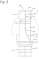
- the body element 211 and the outlet tube 112 are connected to each other via tamper evident members 51, which is better shown in the exploded view of Figure 1B .
- the tamper evident members 51 connect cap 21 and spout 11.
- the tamper evident member 51 connects on one end to the outer surface of the outlet tube 112, and on the other end to the outer surface of the body element 211.
- tethering member 31 connects the cap 21 to the spout 11. However, unlike the tamper evident member 51, tethering member 31 remains connected to the spout 11 and the cap 21 when the cap 21 is opened, i.e. removed from the outlet tube 112 of the spout 11.
- the tethering member 31 may e.g. be shaped as a wire connection, having one end 31A connected to the spout 11 and an opposite end 31B connected to the cap 21. Even though it will typically be possible to break the tethering member 31 when an excessive amount of force is applied to it, or when it is e.g.
- the tethering member 31 connects the cap 21 and the spout 11 at all times, in both the closed position C as well as in the retained position R. As shown, in the closed cap position C, wherein the cap 21 closes off the outlet 114 of the outlet tube 112, the tethering member 31 connects spout 11 and cap 21 so that they form a spout-cap unit 1. Also in the retaining position R, the cap 21 and the spout 11 remain connected via tethering member 31.
- the tethering member 31 While connecting cap 21 and spout 11, the tethering member 31 allows the cap 21 to be moved away from its closed position C, towards a retaining position R below the closed position C and to the side of the closed position C as shown, exposing the outlet 114 of the outlet tube 112 so that a user can e.g. drink the consumable of the pouch.
- the cap 21 is coupled with retaining member 113 of the spout 11.
- the cap 21 is clicked on the retaining member 113.
- the tethering member 31 is shaped in such a way that a compressive or tensile force is enacted on the cap 21 when the cap 21 is in the retained position R, so that the cap 21 remains in the retained position R more securely.
- FIG. 3 an embodiment of the spout-cap unit 1 somewhat similar to the embodiment of Figure 2 is shown.
- the part where the outlet tube 112 and the body element 211 of cap 21 are arranged over one another is worked open, to explain how the unit 1 can be made via an injection moulding process.
- outlet tube 112 and cap 21 are substantially spaced apart from each other.
- the only point where the body element 211 and the outlet tube 112 are connected is the tamper evident seal 52, here located at the inner side of the cap 21, in between cap 21 and outlet tube 112.
- the tamper evident seal 52 of the embodiment shown here is too small to allow all material of the cap 21 to be reliable injected for the formation of body element 211 of cap 21 when a single injection moulding step is desired.
- the tamper evident members are e.g. arranged at the outside of the cap 21, they may be large enough to allow the material of the body element 211 to be filled therethrough during injection moulding.
- retaining members 113 there may be two retaining members 113, one on the right (where the cap 21 is placed) and one on the left. In such an embodiment, a user can choose where the cap 21 is placed in the retained position R. In principle, one retaining member 113 will however be sufficient.
- the retaining members 113 are formed as projection members on the outlet tube 112.
- the cap 21 comprises a flange 218 near the lower edge thereof.
- the flange 218 can be hooked under the protrusion 113, to retain the cap 21 in the retained position R.
- some tension force is applied on the cap 21 in such an embodiment by the tethering member 31, so that the cap 21 is reliable secured in the retaining position R.
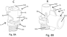
- FIGS 8A and 8B show a further embodiment of the spout-cap unit 1.
- the tethering member 31 is here generally W-shaped and connected to the spout unit 11 on one end and to the cap unit 21 on the other end.
- the generally W-shaped form of the tethering member 31 allows the cap 21 to be easily pulled upwards from a closed position C as indicated in Figure 8A to a released position (not shown). From the released position the cap 21 may be mounted on the retaining member 113 indicated in Figure 8B to bring the cap 21 into its retained position.
- the W shape of the tethering member 31 provides a sufficient length to release the cap 21 from the spout 11.
- FIG. 9A - 9C is comparable to the embodiment shown in Figures 8A and 8B , with the difference that the cap part 21 here has a cut-out.
- the tethering member 31 is housed in said cut-out.
- This has the technical advantage that the tethering member 31 is less prone to breaking and being damaged while being transported and on a shelf of a store.
- It can have the further technical advantage that when the cap 21 is turned 90 degrees compared to its closed position (closed position C shown in Figure 9A ; turned position shown in Figure 9B ), a protruding lip is formed. This lip can then easily and reliably be coupled with retaining member 113 to position the cap 21 in the retaining position R.
- the open, lower end of the cap 21 engages with the retaining member 113 to retain the cap 21.
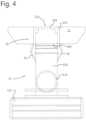
- a ring member 33 is visible.
- the ring member 33 encloses a body portion of the cap 21, the ring member 33 being enclosed in between a flange 218 at the lower edge of the cap 21 and grip element 41 at the upper edge of the cap 21.
- Attached to the ring member 33 is tethering member 31, the tethering member 31 in this way being coupled with the cap 21.
- body portion of the cap 21 can move up and down with respect to the ring element 33, so that the cap 21 can be pulled from the outlet tube 112 of the spout 11 without needing to stretch the tethering member 31 too much ( Figure 10B ) as the ring member 33 remains at a stationary position compared to outlet 112 as the cap 21 moves upwards.
- ring member 33 moves from a position adjacent the grip member 41 to a position adjacent flange 218.
- the tethering member 31 can be of a relatively short length, while still allowing the cap 21 to be removed from the spout 11 and remaining attached to it.
- the ring member 33 is then moved to its upper position adjacent grip element 41 again to couple the cap 21 with the retaining member 113 at a position fully below the outlet tube 112.
- the protruding corners of the grip element 41 which are gripped by a user to open the cap 21, can be clamped in the retaining member 113 of the spout 11 to retain the cap 21 in the retaining position R.
- the tethering member 31 is of a more substantial width than in the other embodiments and has a cut-out in the lower middle part thereof. As such, the tethering member 31 itself can be coupled with the retaining member 113 in the way shown in Figure 11C .
- a ring member 33 which encloses the body of the cap 21 is used to allow the cap 21 to be removed from the spout 11 without the tethering member 31 elongating too much.
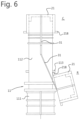
- a cap-spout unit 1 that is made from two components: a plug element 214 and a spout-cap-assembly having an open cap body element 211.
- the spout-cap-assembly is made as a single injection moulding part, including sealboat 111, outlet tube 112, retaining member 113, cap body element 211 and retaining member 31, including ring element 33.
- cap body element 211 and outlet tube 112 are separated from each other except for at the tamper evident connectors 51. It is also via these tamper evident connectors 51 that the cap body element 211 can be injection moulded. It is further noted that ring element 33 and cap body element 211 are separated from each other.
- Figure 12A shows the spout-cap-assembly with an open-ended cap and the outlet tube 112 of the spout part 11 left open. This advantageously allows the spout-cap-assembly to be sealed to a pouch before said pouch is filled.
- plug element 219 is mounted onto the cap body element 211. As such the outlet 112 of the spout part 11 is closed and the cap 21 is formed. Attention is drawn to ramp 116 at the surface of the spout part 11 that faces the bottom of the cap part, notch 216 on the side of the cap part 21 and the tamper evident connectors 51 in between notch 216 and ramp 116. Turning now to Figure 12C , the tamper evident connectors 51 can be broken by turning cap 21 and moving notch 216 up on the ramp 116. In this way, the cap 21 is unsealed. It is noted that in this unsealed position, the radial projection 219 of the cap 21, as defined by the plug element 214, contacts the ring element 33
- the cap 21 may be moved upwards with respect to the outlet tube 211. Even though the cap part 21 moves, it remains coupled with the spout part 11 as the ring element 33 of the tethering member 31 and the flange 218 of the cap part 21 together prevent the separation of cap 21 from spout 11.
- the cap part 21 may be rotated to the side, and free outlet tube 112. As shown, the cap part 21 may be manipulated towards a retaining position R in which the tethering member 31 is coupled with retaining member 113, to fixate the cap in the retaining position R. It is noticed that both the lateral and the vertical separation between cap 21 and outlet tube 112 is quite large in the retained position R, with the cap 21 most notably being completely below the outlet tube 112. This makes it highly comfortable to drink from the outlet tube 112 without noticing the cap 21 at all.
- Figure 13 can be seen as a cross sectional view of Figure 12B .
- the spout-cap-assembly including seal boat 111, outlet tube 112, retaining member 113, tethering member 31, ring element 33, cap body element 211 and tamper evident connectors (not shown) are manufactured as one part, whereas the plug element 214 is manufactured as a separate part. Due to concentric annular grooves 2141, 2142 defined between inner walls 2144, 2145 and inner walls 2143, 2144 of the plug element 214, the plug element 214 may be connected with the spout-cap assembly.
- connection between cap body element 211 and outer groove 2141 may be unreleasable, whereas the connection between outlet tube 112 and inner groove 2142 may be releasable - to allow the cap 21 to be separated from the outlet tube 112, but to prevent separation between plug element 214 and cap 21.
- a further connection may be established between a circumferential recess 2146 at the most inner wall 2145 of the plug element 214 and a complementary circumferential projection 1121 at the inner wall of the outlet tube 112.
- At least the spout-cap units 1 shown in Figures 7 - 13 can be transported in a "standard” spout transport rail as in use today, despite a tethering member 31 and a cap 21 being "added” to the spout 11 as compared to known spouts.
- This is an important requirement, as this allows the spout-cap unit 1 as presented herein to be put to use in spout processing factories across the globe without the need for new equipment in said factories.
Landscapes
- Engineering & Computer Science (AREA)
- Mechanical Engineering (AREA)
- Closures For Containers (AREA)
- Bag Frames (AREA)
Claims (12)
- Unité de bec verseur-capuchon (1) comprenant :une partie de bec verseur (11) comprenant une bague d'étanchéité (111), un tube de sortie (112) et un organe de retenue (113) ; etune partie de capuchon (21) pour fermer une sortie (114) du tube de sortie (112) dans une position fermée (C) de la partie de capuchon (21) ;dans laquelle la partie de bec verseur (11) et la partie de capuchon (21) sont attachées ensemble via au moins un organe d'attache (31, 32) pour former l'unité de bec verseur-capuchon (1), l'organe d'attache (31, 32) étant relié à la partie de bec verseur (11) au niveau d'une extrémité (31A, 32A) de l'organe d'attache (31, 32),dans laquelle la partie de capuchon (21) peut être libérée du tube de sortie (112) de la partie de bec verseur (11) pour fournir la partie de capuchon (21) dans un état libéré (S),dans laquelle, dans ledit état libéré (S), l'organe d'attache (31, 32) permet à la partie de capuchon (21) d'être déplacée vers une position de retenue (R) qui est positionnée loin de la sortie (114) du tube de sortie (112),dans laquelle l'organe d'attache (31, 32) peut être couplé à l'organe de retenue (113) de la partie de bec verseur (11) pour retenir la partie de capuchon (21) à la position de retenue (R),caractérisée en ce quela partie de capuchon (21) comprend une bride (218) au niveau de son bord inférieur, une saillie radiale (219) au niveau de son bord supérieur et un élément de corps (211) entre les deux ;l'organe d'attache (31, 32) comprend un élément annulaire (33) qui entoure la partie de capuchon (21) au niveau de l'extrémité opposée (31B, 32B) de l'organe d'attache (31, 32) ;la partie de capuchon (21) est mobile vers le haut par rapport au tube de sortie (112) de la partie de bec verseur (11) ; etdans ledit état de libéré (S), la partie de capuchon (21) et la partie de bec verseur (11) restent attachées ensemble via l'élément annulaire (33) de l'organe d'attache (31, 32).
- Unité de bec verseur-capuchon selon la revendication 1, dans laquelle la distance entre la bride (218) et la saillie radiale (219) du capuchon (21) dépasse 8 mm.
- Unité de bec verseur-capuchon selon la revendication 1 ou 2, dans laquelle la partie de capuchon (21) et la partie de bec verseur (11) sont réalisées en le même matériau.
- Unité de bec verseur-capuchon selon l'une quelconque des revendications précédentes, dans laquelle l'unité de bec verseur-capuchon (1) est moulée par injection, de préférence en une seule étape de moulage par injection.
- Unité de bec verseur-capuchon selon l'une quelconque des revendications précédentes, dans laquelle l'unité de bec verseur-capuchon (1) est réalisée en une seule pièce.
- Unité de bec verseur-capuchon selon l'une quelconque des revendications précédentes, dans laquelle un bord supérieur (219) de l'unité de capuchon (21) a un diamètre qui est supérieur au diamètre de son corps (211).
- Unité de bec verseur-capuchon selon l'une quelconque des revendications précédentes, dans laquelle la partie de capuchon (21) et la partie de bec verseur (11) sont exemptes de filetage de vis.
- Unité de bec verseur-capuchon selon l'une quelconque des revendications précédentes, dans laquelle les dimensions externes de la partie de capuchon (21) et de l'organe d'attache (31, 32) ont une largeur (w) d'au plus 24 mm et/ou ont une hauteur (h) d'au plus 19 mm.
- Unité de bec verseur-capuchon selon l'une quelconque des revendications précédentes, dans laquelle une liaison inviolable (51, 52) relie en outre la partie de bec verseur (11) et la partie de capuchon (21) l'une à l'autre lorsque la partie de capuchon (21) n'a pas été ouverte.
- Unité de bec verseur-capuchon selon l'une quelconque des revendications précédentes, dans laquelle la partie de bec verseur (11) comprend une rampe (116) au niveau de la surface (115) qui fait face à l'ouverture inférieure (213) de la partie de capuchon (21), et dans laquelle le bord (215) de la partie de capuchon (21) qui fait face à la rampe (116) de la partie de bec verseur (11) comprend une encoche (216), une forme de l'encoche (216) correspondant à la forme de la rampe (116), dans laquelle l'encoche (216) a de préférence un bord sensiblement droit (217) au niveau d'une extrémité de celle-ci.
- Unité de bec verseur-capuchon selon l'une quelconque des revendications précédentes, dans laquelle la position de retenue (R) de la partie de capuchon (21) est située sur le côté de et/ou en dessous de la position fermée (C) de la partie de capuchon (21).
- Poche (61) comprenant une unité de bec verseur-capuchon (1) selon l'une quelconque des revendications précédentes.
Applications Claiming Priority (4)
| Application Number | Priority Date | Filing Date | Title |
|---|---|---|---|
| NL2028309A NL2028309B1 (en) | 2021-05-27 | 2021-05-27 | Spout-cap unit, pouch comprising such a spout-cap unit, and method for manufacturing the spout-cap unit. |
| NL2028901 | 2021-08-02 | ||
| PCT/NL2022/050289 WO2022250537A1 (fr) | 2021-05-27 | 2022-05-25 | Unité de capuchon de bec verseur, poche comprenant une telle unité de capuchon de bec verseur |
| EP22732349.0A EP4132864B1 (fr) | 2021-05-27 | 2022-05-25 | Unité de capuchon de bec verseur, poche comprenant une telle unité de capuchon de bec verseur |
Related Parent Applications (2)
| Application Number | Title | Priority Date | Filing Date |
|---|---|---|---|
| EP22732349.0A Division EP4132864B1 (fr) | 2021-05-27 | 2022-05-25 | Unité de capuchon de bec verseur, poche comprenant une telle unité de capuchon de bec verseur |
| EP22732349.0A Division-Into EP4132864B1 (fr) | 2021-05-27 | 2022-05-25 | Unité de capuchon de bec verseur, poche comprenant une telle unité de capuchon de bec verseur |
Publications (4)
| Publication Number | Publication Date |
|---|---|
| EP4245499A2 EP4245499A2 (fr) | 2023-09-20 |
| EP4245499A3 EP4245499A3 (fr) | 2023-12-20 |
| EP4245499C0 EP4245499C0 (fr) | 2025-07-02 |
| EP4245499B1 true EP4245499B1 (fr) | 2025-07-02 |
Family
ID=82117202
Family Applications (2)
| Application Number | Title | Priority Date | Filing Date |
|---|---|---|---|
| EP22732349.0A Active EP4132864B1 (fr) | 2021-05-27 | 2022-05-25 | Unité de capuchon de bec verseur, poche comprenant une telle unité de capuchon de bec verseur |
| EP23188842.1A Active EP4245499B1 (fr) | 2021-05-27 | 2022-05-25 | Unité de capuchon de bec verseur, poche comprenant une telle unité de capuchon de bec verseur |
Family Applications Before (1)
| Application Number | Title | Priority Date | Filing Date |
|---|---|---|---|
| EP22732349.0A Active EP4132864B1 (fr) | 2021-05-27 | 2022-05-25 | Unité de capuchon de bec verseur, poche comprenant une telle unité de capuchon de bec verseur |
Country Status (4)
| Country | Link |
|---|---|
| US (1) | US12492048B2 (fr) |
| EP (2) | EP4132864B1 (fr) |
| ES (2) | ES2961152T3 (fr) |
| WO (1) | WO2022250537A1 (fr) |
Families Citing this family (2)
| Publication number | Priority date | Publication date | Assignee | Title |
|---|---|---|---|---|
| IT202000019939A1 (it) * | 2020-08-11 | 2022-02-11 | Guala Pack Spa | Chiusura per una cannuccia di un imballo a pareti sottili |
| EP4524052B1 (fr) * | 2023-09-12 | 2026-04-29 | LD Packaging(Foshan) Co., Ltd | Couvercle de sécurité et ensemble buse d'aspiration associé |
Family Cites Families (17)
| Publication number | Priority date | Publication date | Assignee | Title |
|---|---|---|---|---|
| FR2647088B1 (fr) * | 1989-05-17 | 1991-11-22 | Rical Sa | Ensemble verseur et capsule de bouchage avec charniere a ressort |
| ATE137193T1 (de) | 1991-04-26 | 1996-05-15 | Guala Spa | Elastischer spender für viskose produkte |
| US5911340A (en) | 1995-09-14 | 1999-06-15 | Dai Nippon Printing Co., Ltd. | Spout assembly, spout assembly manufacturing apparatus and package with spout assembly |
| NL1018233C2 (nl) * | 2001-06-07 | 2002-12-10 | Itsac Nv | Afgiftetuit- en dopsamenstel. |
| JP2005516850A (ja) * | 2001-09-10 | 2005-06-09 | リー、ジュンミン | スパウトアセンブリ |
| AU2003284737A1 (en) * | 2002-11-21 | 2004-07-29 | Jung-Min Lee | Spout assembly with a rubber or cork plug |
| US7607555B2 (en) * | 2006-03-01 | 2009-10-27 | Ds Smith Plastics Limited | Puncturable cap and piercer |
| KR100807212B1 (ko) * | 2006-10-18 | 2008-02-28 | 권시중 | 연결부재가 구비된 마개 분실방지 용기 |
| ITBS20060190A1 (it) | 2006-10-27 | 2008-04-28 | Guala Pack Spa | Tappo per contenitore munito di sigillo di garanzia |
| US20080197135A1 (en) | 2007-02-20 | 2008-08-21 | Berman Ronald H | Beverage spout with safety tether |
| DE102007011929A1 (de) * | 2007-03-13 | 2008-09-18 | Georg Menshen Gmbh & Co. Kg | Verschluss für einen Behälter |
| US8646633B2 (en) * | 2009-12-16 | 2014-02-11 | Johnson & Johnson Vision Care Inc | Closure for containers of ophthalmic solutions containing a spout cap |
| WO2015023829A1 (fr) | 2013-08-16 | 2015-02-19 | Mwv Slatersville, Llc | Dispositif de fermeture distributeur |
| NL2015473B1 (en) * | 2015-09-21 | 2017-04-19 | Scholle Ipn Ip Bv | A spouted pouch adapted to be filled with a flowable product. |
| DE102019002719A1 (de) * | 2019-04-15 | 2020-10-15 | Georg Menshen Gmbh & Co. Kg | Verschluss eines Auslassstutzens |
| US11059633B2 (en) * | 2019-10-31 | 2021-07-13 | Cheer Pack North America | Flip-top closure for container |
| US11918540B2 (en) * | 2020-04-23 | 2024-03-05 | Vonco Products, Llc | Cap for spout and modified spout |
-
2022
- 2022-05-25 EP EP22732349.0A patent/EP4132864B1/fr active Active
- 2022-05-25 WO PCT/NL2022/050289 patent/WO2022250537A1/fr not_active Ceased
- 2022-05-25 ES ES22732349T patent/ES2961152T3/es active Active
- 2022-05-25 EP EP23188842.1A patent/EP4245499B1/fr active Active
- 2022-05-25 ES ES23188842T patent/ES3036806T3/es active Active
- 2022-05-25 US US18/564,259 patent/US12492048B2/en active Active
Also Published As
| Publication number | Publication date |
|---|---|
| EP4245499A2 (fr) | 2023-09-20 |
| WO2022250537A1 (fr) | 2022-12-01 |
| EP4245499A3 (fr) | 2023-12-20 |
| US20240239564A1 (en) | 2024-07-18 |
| ES3036806T3 (en) | 2025-09-24 |
| EP4132864C0 (fr) | 2023-09-06 |
| ES2961152T3 (es) | 2024-03-08 |
| US12492048B2 (en) | 2025-12-09 |
| EP4132864B1 (fr) | 2023-09-06 |
| EP4245499C0 (fr) | 2025-07-02 |
| EP4132864A1 (fr) | 2023-02-15 |
Similar Documents
| Publication | Publication Date | Title |
|---|---|---|
| US6419101B1 (en) | Tear band closure | |
| US20230042976A1 (en) | Container closure | |
| US20100140268A1 (en) | Dispensing closure with removable membrane | |
| EP3908534B1 (fr) | Capuchon avec renfoncement accueillant une bande d'inviolabilité | |
| US6257453B1 (en) | Tamper-indicating, two-piece dispensing closure | |
| US20070017939A1 (en) | Directional pour spout container cap | |
| EP4245499B1 (fr) | Unité de capuchon de bec verseur, poche comprenant une telle unité de capuchon de bec verseur | |
| US20220227542A1 (en) | Closure for a container and components for a closure | |
| WO2004046013A2 (fr) | Fermeture d'etancheite centrale a ressort de re-etancheite autoreglable | |
| US7810681B2 (en) | Internal container bore mount fitment | |
| CN108473237A (zh) | 封闭件 | |
| CA2492900A1 (fr) | Fermeture pour boisson comprenant un goulot ouvert/ferme et des surfaces d'etancheite protegees | |
| US20240132255A1 (en) | Hinged Closure | |
| US7114625B2 (en) | Twist cap | |
| US8820550B2 (en) | One-piece packaging comprising a container and a closure | |
| AU2003200168A1 (en) | Dispensing closure and package incorporating same | |
| NL2028309B1 (en) | Spout-cap unit, pouch comprising such a spout-cap unit, and method for manufacturing the spout-cap unit. | |
| US8720726B2 (en) | One-piece lid for cartons | |
| JP2024535391A (ja) | 入れ子を可能にする錐台形状の表面を持つねじ付き容器構成部品 | |
| AU2005100040A4 (en) | A closure assembly | |
| US20060175282A1 (en) | Closure assembly | |
| CN116714892A (zh) | 盖子 | |
| JP2007069979A (ja) | キャップホルダー付容器 | |
| CN118317906A (zh) | 具有能够嵌套的平截头体形状的表面的带螺纹的容器部件 | |
| WO2000069743A1 (fr) | Recipient pour boissons liquides |
Legal Events
| Date | Code | Title | Description |
|---|---|---|---|
| PUAI | Public reference made under article 153(3) epc to a published international application that has entered the european phase |
Free format text: ORIGINAL CODE: 0009012 |
|
| STAA | Information on the status of an ep patent application or granted ep patent |
Free format text: STATUS: THE APPLICATION HAS BEEN PUBLISHED |
|
| AC | Divisional application: reference to earlier application |
Ref document number: 4132864 Country of ref document: EP Kind code of ref document: P |
|
| AK | Designated contracting states |
Kind code of ref document: A2 Designated state(s): AL AT BE BG CH CY CZ DE DK EE ES FI FR GB GR HR HU IE IS IT LI LT LU LV MC MK MT NL NO PL PT RO RS SE SI SK SM TR |
|
| REG | Reference to a national code |
Ref legal event code: R079 Ref country code: DE Ref legal event code: R079 Ref document number: 602022017131 Country of ref document: DE Free format text: PREVIOUS MAIN CLASS: B29C0045000000 Ipc: B65D0047140000 |
|
| PUAL | Search report despatched |
Free format text: ORIGINAL CODE: 0009013 |
|
| AK | Designated contracting states |
Kind code of ref document: A3 Designated state(s): AL AT BE BG CH CY CZ DE DK EE ES FI FR GB GR HR HU IE IS IT LI LT LU LV MC MK MT NL NO PL PT RO RS SE SI SK SM TR |
|
| RIC1 | Information provided on ipc code assigned before grant |
Ipc: B29C 45/00 20060101ALI20231113BHEP Ipc: B65D 55/16 20060101ALI20231113BHEP Ipc: B65D 75/58 20060101ALI20231113BHEP Ipc: B65D 47/14 20060101AFI20231113BHEP |
|
| STAA | Information on the status of an ep patent application or granted ep patent |
Free format text: STATUS: REQUEST FOR EXAMINATION WAS MADE |
|
| STAA | Information on the status of an ep patent application or granted ep patent |
Free format text: STATUS: EXAMINATION IS IN PROGRESS |
|
| 17P | Request for examination filed |
Effective date: 20240618 |
|
| RBV | Designated contracting states (corrected) |
Designated state(s): AL AT BE BG CH CY CZ DE DK EE ES FI FR GB GR HR HU IE IS IT LI LT LU LV MC MK MT NL NO PL PT RO RS SE SI SK SM TR |
|
| 17Q | First examination report despatched |
Effective date: 20240723 |
|
| GRAP | Despatch of communication of intention to grant a patent |
Free format text: ORIGINAL CODE: EPIDOSNIGR1 |
|
| STAA | Information on the status of an ep patent application or granted ep patent |
Free format text: STATUS: GRANT OF PATENT IS INTENDED |
|
| INTG | Intention to grant announced |
Effective date: 20250131 |
|
| GRAS | Grant fee paid |
Free format text: ORIGINAL CODE: EPIDOSNIGR3 |
|
| GRAA | (expected) grant |
Free format text: ORIGINAL CODE: 0009210 |
|
| STAA | Information on the status of an ep patent application or granted ep patent |
Free format text: STATUS: THE PATENT HAS BEEN GRANTED |
|
| AC | Divisional application: reference to earlier application |
Ref document number: 4132864 Country of ref document: EP Kind code of ref document: P |
|
| AK | Designated contracting states |
Kind code of ref document: B1 Designated state(s): AL AT BE BG CH CY CZ DE DK EE ES FI FR GB GR HR HU IE IS IT LI LT LU LV MC MK MT NL NO PL PT RO RS SE SI SK SM TR |
|
| REG | Reference to a national code |
Ref country code: GB Ref legal event code: FG4D |
|
| REG | Reference to a national code |
Ref country code: CH Ref legal event code: EP |
|
| REG | Reference to a national code |
Ref country code: DE Ref legal event code: R096 Ref document number: 602022017131 Country of ref document: DE |
|
| REG | Reference to a national code |
Ref country code: IE Ref legal event code: FG4D |
|
| U01 | Request for unitary effect filed |
Effective date: 20250722 |
|
| U07 | Unitary effect registered |
Designated state(s): AT BE BG DE DK EE FI FR IT LT LU LV MT NL PT RO SE SI Effective date: 20250729 |
|
| REG | Reference to a national code |
Ref country code: ES Ref legal event code: FG2A Ref document number: 3036806 Country of ref document: ES Kind code of ref document: T3 Effective date: 20250924 |
|
| PG25 | Lapsed in a contracting state [announced via postgrant information from national office to epo] |
Ref country code: IS Free format text: LAPSE BECAUSE OF FAILURE TO SUBMIT A TRANSLATION OF THE DESCRIPTION OR TO PAY THE FEE WITHIN THE PRESCRIBED TIME-LIMIT Effective date: 20251102 |
|
| PG25 | Lapsed in a contracting state [announced via postgrant information from national office to epo] |
Ref country code: NO Free format text: LAPSE BECAUSE OF FAILURE TO SUBMIT A TRANSLATION OF THE DESCRIPTION OR TO PAY THE FEE WITHIN THE PRESCRIBED TIME-LIMIT Effective date: 20251002 |
|
| PG25 | Lapsed in a contracting state [announced via postgrant information from national office to epo] |
Ref country code: HR Free format text: LAPSE BECAUSE OF FAILURE TO SUBMIT A TRANSLATION OF THE DESCRIPTION OR TO PAY THE FEE WITHIN THE PRESCRIBED TIME-LIMIT Effective date: 20250702 |
|
| PG25 | Lapsed in a contracting state [announced via postgrant information from national office to epo] |
Ref country code: GR Free format text: LAPSE BECAUSE OF FAILURE TO SUBMIT A TRANSLATION OF THE DESCRIPTION OR TO PAY THE FEE WITHIN THE PRESCRIBED TIME-LIMIT Effective date: 20251003 |
|
| PG25 | Lapsed in a contracting state [announced via postgrant information from national office to epo] |
Ref country code: CZ Free format text: LAPSE BECAUSE OF FAILURE TO SUBMIT A TRANSLATION OF THE DESCRIPTION OR TO PAY THE FEE WITHIN THE PRESCRIBED TIME-LIMIT Effective date: 20250702 |
|
| PG25 | Lapsed in a contracting state [announced via postgrant information from national office to epo] |
Ref country code: PL Free format text: LAPSE BECAUSE OF FAILURE TO SUBMIT A TRANSLATION OF THE DESCRIPTION OR TO PAY THE FEE WITHIN THE PRESCRIBED TIME-LIMIT Effective date: 20250702 |
|
| PG25 | Lapsed in a contracting state [announced via postgrant information from national office to epo] |
Ref country code: RS Free format text: LAPSE BECAUSE OF FAILURE TO SUBMIT A TRANSLATION OF THE DESCRIPTION OR TO PAY THE FEE WITHIN THE PRESCRIBED TIME-LIMIT Effective date: 20251002 |
|
| PG25 | Lapsed in a contracting state [announced via postgrant information from national office to epo] |
Ref country code: SM Free format text: LAPSE BECAUSE OF FAILURE TO SUBMIT A TRANSLATION OF THE DESCRIPTION OR TO PAY THE FEE WITHIN THE PRESCRIBED TIME-LIMIT Effective date: 20250702 |
|
| PGFP | Annual fee paid to national office [announced via postgrant information from national office to epo] |
Ref country code: GB Payment date: 20260306 Year of fee payment: 5 |