EP4249919B1 - Système d'immunodosage automatique - Google Patents
Système d'immunodosage automatique Download PDFInfo
- Publication number
- EP4249919B1 EP4249919B1 EP22188739.1A EP22188739A EP4249919B1 EP 4249919 B1 EP4249919 B1 EP 4249919B1 EP 22188739 A EP22188739 A EP 22188739A EP 4249919 B1 EP4249919 B1 EP 4249919B1
- Authority
- EP
- European Patent Office
- Prior art keywords
- cartridge
- unit
- well
- wells
- tip
- Prior art date
- Legal status (The legal status is an assumption and is not a legal conclusion. Google has not performed a legal analysis and makes no representation as to the accuracy of the status listed.)
- Active
Links
Images


Classifications
-
- G—PHYSICS
- G01—MEASURING; TESTING
- G01N—INVESTIGATING OR ANALYSING MATERIALS BY DETERMINING THEIR CHEMICAL OR PHYSICAL PROPERTIES
- G01N35/00—Automatic analysis not limited to methods or materials provided for in any single one of groups G01N1/00 - G01N33/00; Handling materials therefor
- G01N35/02—Automatic analysis not limited to methods or materials provided for in any single one of groups G01N1/00 - G01N33/00; Handling materials therefor using a plurality of sample containers moved by a conveyor system past one or more treatment or analysis stations
- G01N35/04—Details of the conveyor system
-
- G—PHYSICS
- G01—MEASURING; TESTING
- G01N—INVESTIGATING OR ANALYSING MATERIALS BY DETERMINING THEIR CHEMICAL OR PHYSICAL PROPERTIES
- G01N35/00—Automatic analysis not limited to methods or materials provided for in any single one of groups G01N1/00 - G01N33/00; Handling materials therefor
- G01N35/02—Automatic analysis not limited to methods or materials provided for in any single one of groups G01N1/00 - G01N33/00; Handling materials therefor using a plurality of sample containers moved by a conveyor system past one or more treatment or analysis stations
- G01N35/026—Automatic analysis not limited to methods or materials provided for in any single one of groups G01N1/00 - G01N33/00; Handling materials therefor using a plurality of sample containers moved by a conveyor system past one or more treatment or analysis stations having blocks or racks of reaction cells or cuvettes
-
- G—PHYSICS
- G01—MEASURING; TESTING
- G01N—INVESTIGATING OR ANALYSING MATERIALS BY DETERMINING THEIR CHEMICAL OR PHYSICAL PROPERTIES
- G01N33/00—Investigating or analysing materials by specific methods not covered by groups G01N1/00 - G01N31/00
- G01N33/48—Biological material, e.g. blood, urine; Haemocytometers
- G01N33/50—Chemical analysis of biological material, e.g. blood, urine; Testing involving biospecific ligand binding methods; Immunological testing
- G01N33/53—Immunoassay; Biospecific binding assay; Materials therefor
- G01N33/531—Production of immunochemical test materials
- G01N33/532—Production of labelled immunochemicals
- G01N33/533—Production of labelled immunochemicals with fluorescent label
-
- G—PHYSICS
- G01—MEASURING; TESTING
- G01N—INVESTIGATING OR ANALYSING MATERIALS BY DETERMINING THEIR CHEMICAL OR PHYSICAL PROPERTIES
- G01N21/00—Investigating or analysing materials by the use of optical means, i.e. using sub-millimetre waves, infrared, visible or ultraviolet light
- G01N21/62—Systems in which the material investigated is excited whereby it emits light or causes a change in wavelength of the incident light
- G01N21/63—Systems in which the material investigated is excited whereby it emits light or causes a change in wavelength of the incident light optically excited
- G01N21/64—Fluorescence; Phosphorescence
- G01N21/6428—Measuring fluorescence of fluorescent products of reactions or of fluorochrome labelled reactive substances, e.g. measuring quenching effects, using measuring "optrodes"
-
- G—PHYSICS
- G01—MEASURING; TESTING
- G01N—INVESTIGATING OR ANALYSING MATERIALS BY DETERMINING THEIR CHEMICAL OR PHYSICAL PROPERTIES
- G01N33/00—Investigating or analysing materials by specific methods not covered by groups G01N1/00 - G01N31/00
- G01N33/48—Biological material, e.g. blood, urine; Haemocytometers
- G01N33/50—Chemical analysis of biological material, e.g. blood, urine; Testing involving biospecific ligand binding methods; Immunological testing
- G01N33/53—Immunoassay; Biospecific binding assay; Materials therefor
- G01N33/536—Immunoassay; Biospecific binding assay; Materials therefor with immune complex formed in liquid phase
-
- G—PHYSICS
- G01—MEASURING; TESTING
- G01N—INVESTIGATING OR ANALYSING MATERIALS BY DETERMINING THEIR CHEMICAL OR PHYSICAL PROPERTIES
- G01N35/00—Automatic analysis not limited to methods or materials provided for in any single one of groups G01N1/00 - G01N33/00; Handling materials therefor
- G01N35/00029—Automatic analysis not limited to methods or materials provided for in any single one of groups G01N1/00 - G01N33/00; Handling materials therefor provided with flat sample substrates, e.g. slides
-
- G—PHYSICS
- G01—MEASURING; TESTING
- G01N—INVESTIGATING OR ANALYSING MATERIALS BY DETERMINING THEIR CHEMICAL OR PHYSICAL PROPERTIES
- G01N35/00—Automatic analysis not limited to methods or materials provided for in any single one of groups G01N1/00 - G01N33/00; Handling materials therefor
- G01N35/10—Devices for transferring samples or any liquids to, in, or from, the analysis apparatus, e.g. suction devices, injection devices
- G01N35/1009—Characterised by arrangements for controlling the aspiration or dispense of liquids
-
- B—PERFORMING OPERATIONS; TRANSPORTING
- B01—PHYSICAL OR CHEMICAL PROCESSES OR APPARATUS IN GENERAL
- B01L—CHEMICAL OR PHYSICAL LABORATORY APPARATUS FOR GENERAL USE
- B01L3/00—Containers or dishes for laboratory use, e.g. laboratory glassware; Droppers
- B01L3/50—Containers for the purpose of retaining a material to be analysed, e.g. test tubes
- B01L3/502—Containers for the purpose of retaining a material to be analysed, e.g. test tubes with fluid transport, e.g. in multi-compartment structures
-
- G—PHYSICS
- G01—MEASURING; TESTING
- G01N—INVESTIGATING OR ANALYSING MATERIALS BY DETERMINING THEIR CHEMICAL OR PHYSICAL PROPERTIES
- G01N35/00—Automatic analysis not limited to methods or materials provided for in any single one of groups G01N1/00 - G01N33/00; Handling materials therefor
- G01N35/02—Automatic analysis not limited to methods or materials provided for in any single one of groups G01N1/00 - G01N33/00; Handling materials therefor using a plurality of sample containers moved by a conveyor system past one or more treatment or analysis stations
- G01N35/04—Details of the conveyor system
- G01N2035/0401—Sample carriers, cuvettes or reaction vessels
- G01N2035/0412—Block or rack elements with a single row of samples
- G01N2035/0415—Block or rack elements with a single row of samples moving in two dimensions in a horizontal plane
-
- G—PHYSICS
- G01—MEASURING; TESTING
- G01N—INVESTIGATING OR ANALYSING MATERIALS BY DETERMINING THEIR CHEMICAL OR PHYSICAL PROPERTIES
- G01N35/00—Automatic analysis not limited to methods or materials provided for in any single one of groups G01N1/00 - G01N33/00; Handling materials therefor
- G01N35/10—Devices for transferring samples or any liquids to, in, or from, the analysis apparatus, e.g. suction devices, injection devices
- G01N2035/1027—General features of the devices
- G01N2035/1034—Transferring microquantities of liquid
-
- G—PHYSICS
- G01—MEASURING; TESTING
- G01N—INVESTIGATING OR ANALYSING MATERIALS BY DETERMINING THEIR CHEMICAL OR PHYSICAL PROPERTIES
- G01N21/00—Investigating or analysing materials by the use of optical means, i.e. using sub-millimetre waves, infrared, visible or ultraviolet light
- G01N21/62—Systems in which the material investigated is excited whereby it emits light or causes a change in wavelength of the incident light
- G01N21/63—Systems in which the material investigated is excited whereby it emits light or causes a change in wavelength of the incident light optically excited
- G01N21/64—Fluorescence; Phosphorescence
- G01N21/645—Specially adapted constructive features of fluorimeters
-
- G—PHYSICS
- G01—MEASURING; TESTING
- G01N—INVESTIGATING OR ANALYSING MATERIALS BY DETERMINING THEIR CHEMICAL OR PHYSICAL PROPERTIES
- G01N33/00—Investigating or analysing materials by specific methods not covered by groups G01N1/00 - G01N31/00
- G01N33/48—Biological material, e.g. blood, urine; Haemocytometers
- G01N33/50—Chemical analysis of biological material, e.g. blood, urine; Testing involving biospecific ligand binding methods; Immunological testing
- G01N33/68—Chemical analysis of biological material, e.g. blood, urine; Testing involving biospecific ligand binding methods; Immunological testing involving proteins, peptides or amino acids
- G01N33/6803—General methods of protein analysis not limited to specific proteins or families of proteins
-
- G—PHYSICS
- G01—MEASURING; TESTING
- G01N—INVESTIGATING OR ANALYSING MATERIALS BY DETERMINING THEIR CHEMICAL OR PHYSICAL PROPERTIES
- G01N35/00—Automatic analysis not limited to methods or materials provided for in any single one of groups G01N1/00 - G01N33/00; Handling materials therefor
- G01N35/10—Devices for transferring samples or any liquids to, in, or from, the analysis apparatus, e.g. suction devices, injection devices
Definitions
- the present invention relates to an automatic immunoassay system, and more particularly to an automatic immunoassay system capable of performing photo-oxidation fluorescence amplification assay with greater convenience through automatic movement of a tip to a plurality of wells containing solutions performing different roles, respectively.
- Methods for assay of biomolecules include immunoassays, DNA hybridization, receptor-based assay, and the like.
- a detection method for assay of the biomolecules is broadly used not only in laboratory assay, but also in medical diagnosis or development of new medicines.
- enzyme-linked immunosorbent assay is an experimental method that confirms an antigen-antibody reaction through an enzyme bound to an antibody, and is mainly used to perform qualitative and quantitative assay of the antibody or antigen.
- the enzyme-linked immunosorbent assay is a simple and accurate test method and can analyze many samples at once.
- Korean Patent Registration No. 10-1809645 (Title of the Invention: Automatic immunoassay system, Issue Date: December 15, 2017 )
- JP 2008-014636 A relates an autoanalyzer, equipped with a cartridge selection means 2 having a cartridge receiving part 1 to which a plurality of the inspection cartridges 10, can be set and selecting the cartridge receiving part 1 to successively transfer the same to the inspection initial position ST1 in a set stage ST, a cartridge feed means 3 for linearly feeding the inspection cartridges 10 before inspection, which is transferred to and selected at the inspection initial position ST1, in an inspection stage KT by the cartridge selection means 2 and linearly feed out the inspection cartridges 10 before inspection to the set stage ST, a specimen reagent dispensing means 4 for dispensing the specimen and reagent of the inspection cartridge 10 in a reaction cell with respect to the inspection cartridge 10 in the inspection stage KT fed in by the cartridge feed means 3 and a measuring means 5 for measuring the reaction of the specimen and reagent in the reaction cell 11c dispensed by the specimen and reagent dispensing means 4.
- EP 2 154 513 A1 relates to a photometric apparatus and an automatic analyzer in which liquid samples contained in
- US 5,324,635 relates to an analyzer having a reaction disk for holding a plurality of reaction containers and a fluorophotometer for measuring fluorescence stemming from solutions in the containers.
- US 2021/0311033 A1 relates to an ELISA-based, liquid-phase immunoassay apparatus optimized for detecting particular ingredients contained in a biological sample, etc., and a method therefor.
- US 2021/0270819 A1 relates to a device for carrying out heterogeneous immunoassays by means of magnetic particles in cuvettes lined up next to one another, wherein each cuvette has a filling opening and at least one lateral measurement window which is transparent to the measurement radiation.
- US 2021/0041472 A1 relates to a method and/or a device for carrying out chemical, biochemical and/or immunochemical analyses of liquid samples, which are present in a sample store of an automatic analyzer, with the aid of liquid reagents which are present in at least one reagent store of the analyzer.
- Embodiments of the present invention are conceived to solve such problems in the art and it is an object of the present invention to provide an automatic immunoassay system capable of performing photo-oxidation fluorescence amplification assay with greater convenience through automatic movement of a tip to a plurality of wells containing solutions performing different roles, respectively.
- an automatic immunoassay system includes: a case provided with a holding plate therein; a cartridge unit disposed inside the case to be coupled to the holding plate and formed with a plurality of wells; a light source unit disposed at one side of the cartridge unit to emit light to the wells; a sensing unit disposed at the other side of the cartridge unit to detect a fluorescence signal generated by light delivered to the wells; a cartridge conveyance unit coupled to the cartridge unit and the holding plate and moving the cartridge unit on the holding plate in a horizontal direction; a tip disposed above the cartridge unit to be sequentially dipped in the plurality of wells; and a tip conveyance unit coupled to an upper surface of the holding plate and moving the tip in an upward/downward direction.
- the system further comprises: a shutter unit (8000) disposed between the light source unit (3000) and the wells to block light emitted from the light source unit (3000) to the wells or allow the light emitted from the light source unit (3000) to reach the wells, wherein the shutter unit (8000) comprises: a shutter body (8200) disposed between the light source unit (3000) and the wells to block light emitted from the light source unit (3000) from being delivered to the wells; and a shutter pushing portion (8100) coupled to an upper portion of the holding plate (1100) to move the shutter body (8200).
- the cartridge unit may include: a well cartridge provided with the plurality of wells; and a cartridge loading mechanism coupled to a lower portion of the well cartridge to couple the well cartridge to the holding plate.
- the cartridge conveyance unit may include: a cartridge mount coupling the cartridge unit to the holding plate; and a cartridge conveyer conveying the cartridge mount in a horizontal direction with reference to the holding plate.
- the tip conveyance unit may include: a tip holder holding the tip; and a tip conveyer conveying the tip holder in the upward/downward direction.
- the automatic immunoassay system according to the present invention provides the following effects.
- the automatic immunoassay system enables photo-oxidation fluorescence amplification assay with greater convenience through automatic movement of a tip to a plurality of wells containing solutions performing different roles.
- the plurality of wells containing solutions performing different roles is disposed in a single cartridge, and the light source unit is integrally formed with the sensing unit, thereby enabling photo-oxidation fluorescence amplification assay with greater convenience.
- the automatic immunoassay system includes a shutter unit disposed between the light source unit and the wells to block light emitted from the light source unit to the wells or to allow the light emitted from the light source unit to reach the wells, thereby enabling more accurate assay through irradiation of the well with the light emitted from the light source unit after completion of warm-up of the light source unit so as to allow irradiation of a sample with uniform light when there is a need for warm-up of the light source unit.
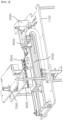
- FIG. 1 and FIG. 2 are schematic views of an automatic immunoassay system according to the present invention.
- the automatic immunoassay system includes a case 1000, a cartridge unit 2000, a light source unit 3000, a sensing unit 4000, a cartridge conveyance unit 5000, a tip 6000, a tip conveyance unit 7000, and a shutter unit 8000.
- the cartridge unit 2000, the light source unit 3000, the sensing unit 4000, the cartridge conveyance unit 5000, the tip 6000, the tip conveyance unit 7000, and the shutter unit 8000 are disposed to allow the automatic immunoassay system according to the present invention to be conveniently carried out by a user.
- the case 1000 may be formed at an upper portion thereof with a gripper and is provided therein with a holding plate 1100 to which the cartridge unit 2000, the light source unit 3000, the sensing unit 4000, the cartridge conveyance unit 5000, the tip 6000, the tip conveyance unit 7000, and the shutter unit 8000 are coupled.
- the holding plate 1100 may be disposed parallel to the ground and be separated a constant distance from a lower surface of the case 1000.
- the cartridge unit 2000 is disposed inside the case 1000 and is coupled to the holding plate 1100.
- the cartridge unit 2000 is formed with a plurality of wells, which contain a coating solution, an antibody-antigen reaction solution, a cleaning solution, and an enzyme-matrix reaction solution to perform photo-oxidation fluorescence amplification assay.
- the light source unit 3000 is disposed at one side of the cartridge unit 2000 to emit light to the wells.
- the cartridge conveyance unit 5000 is coupled to the cartridge unit 2000 and the holding plate 1100 to convey the cartridge unit 2000 on the holding plate 1100 in a horizontal direction.
- the well cartridge 2100 is provided with the plurality of wells in which the tip 6000 is sequentially dipped.
- the cartridge loading mechanism 2200 is coupled to a lower portion of the well cartridge 2100 to couple the well cartridge 2100 to the cartridge conveyance unit 5000.
- the light source unit 3000 includes a first light source 3100, a second light source 3200, and a light source unit mounting block 3300.
- the first light source 3100 is disposed at one side of the seventh well 2180 to emit light to the seventh well 2180 and the second light source 3200 is disposed at one side of the eighth well 2190 to emit light to the eighth well 2190.
- the light source unit mounting block 3300 is disposed at one side of the cartridge loading mechanism 2200 and the light source unit 3000 is mounted on the light source unit mounting block 3300.
- the sensing unit 4000 is disposed at the other side of the seventh well 2180 and the eighth well 2190 of the well cartridge 2100 to detect a fluorescence signal generated by light delivered to the wells.
- the sensing unit 4000 includes a first sensor 4100, a second sensor 4200, and a sensing unit mounting block 4300.
- the first sensor 4100 is disposed at the other side of the seventh well 2180 to detect a fluorescence signal generated by light delivered to the seventh well 2180
- the second sensor 4200 is disposed at the other side of the eighth well 2190 to detect a fluorescence signal generated by light delivered to the eighth well 2190.
- the automatic immunoassay system may include an assay unit (not shown), which analyzes the fluorescence signals detected by the sensing unit 4000.
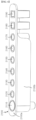
- FIG. 4 is a view of the well cartridge 2100 in the automatic immunoassay system according to the present invention.
- the well cartridge 2100 includes a tip storage well 2110, first to eighth wells 2120 to 2190, a well holder 2100a, and a well protecting portion 2100b.
- the tip storage well 2110 and the first to fourth wells 2120 to 2190 are formed in a tube shape such that the tip 6000 can be inserted thereinto, and are integrally formed with one another to be coupled to one another.
- the tip storage well 2110 defines a standby space for the tip 6000 before conveyance of the tip and receives the tip 6000 therein.
- the first to fourth wells 2120 to 2190 receive the coating solution and the antibody-antigen reaction solution such that the tip 6000 is sequentially received in the first to fourth wells 2120 to 2150 to form an antibody-antigen complex on the tip 6000.
- the seventh well 2180 and the eighth well 2190 receive the enzyme-matrix reaction solution such that the amount of an antigen coupled to an antibody can be measured through enzyme-matrix reaction of the tip 6000 therewith in these wells.
- the seventh well 2180 is a test target well and the eighth well 2190 is a reference well for comparison with the seventh well 2180.
- the tip storage well 2110 and the first to eighth wells 2120 to 2190 are sequentially disposed such that the tip 6000 can conveniently perform antibody-antigen immunoassay and can check fluorescence reaction while moving in the horizontal direction.
- the well holder 2100a is coupled to an outer periphery of an upper surface of each of the tip storage well 2110 and the first to eighth wells 2120 to 2190 such that the tip storage well 2110 is integrated with the first to eighth wells 2120 to 2190.
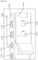
- FIG. 5 is a view of the cartridge loading mechanism 2200 in the automatic immunoassay system according to the present invention.
- the cartridge loading mechanism 2200 includes a well support 2210 and a well cover 2220.
- the well support 2210 is coupled at a lower portion thereof to the cartridge conveyance unit 5000 and is formed at an upper portion thereof with a plurality of well insertion holes 2211, into which lower portions of the first to eighth wells 2120 to 2190 are inserted.
- the well insertion holes 2211 are formed in a shape surrounding the lower portions of the first to eighth wells 2120 to 2190, respectively, such that the well support 2210 supports and secures the first to eighth wells 2120 to 2190 when the first to eighth wells 2120 to 2190 are inserted into the well insertion holes 2211.
- the well cover 2220 protrudes from an upper surface of the well support 2210 to surround the seventh well 2180 and the eighth well 2190 in the well support 2210.
- the well cover 2220 is formed at one side thereof with a first cover hole 2221 and a second cover hole 2222 such that one side of each of the seventh well 2180 and the eighth well 2190 is open through the corresponding cover hole.
- the well cover 2220 is formed at the other side thereof with a third cover hole 2223 and a fourth cover hole 2224 such that the other side of each of the seventh well 2180 and the eighth well 2190 is open through the corresponding cover hole.
- FIG. 6 is a view of the light source unit mounting block 3300 in the automatic immunoassay system according to the present invention. Referring to FIG. 6 , the light source unit mounting block 3300 is coupled to one side of the well cover 2220.
- the light source unit mounting block 3300 is formed with a first light source coupling hole 3310 and a second light source coupling hole 3320 in regions thereof corresponding to the first cover hole 2221 and the second cover hole 2222.
- the first light source 3100 is inserted into and coupled to the first light source coupling hole 3310 and the second light source 3200 is inserted into and coupled to the second light source coupling hole 3320 such that the light source unit 3000 can emit light towards the seventh well 2180 and the eighth well 2190.
- FIG. 7 is a view of the sensing unit mounting block 4300 in the automatic immunoassay system according to the present invention.
- the sensing unit mounting block 4300 is coupled to the other side of the well cover 2220.
- the sensing unit mounting block 4300 includes a sensing unit-insertion block 4310 and a sensing printed circuit board 4320.
- the sensing unit-insertion block 4310 is coupled to the other side of the well cover 2220 and is formed with a first sensor coupling hole 4311 and a second sensor coupling hole 4312 in regions thereof corresponding to the third cover hole 2223 and the fourth cover hole 2224.
- the first sensor 4100 is inserted into and coupled to the first sensor coupling hole 4311 and the second sensor 4200 is inserted into and coupled to the second sensor coupling hole 4312 such that the sensing unit 4000 can detect a fluorescence signal generated by light delivered to the seventh well 2180 and the eighth well 2190.
- the sensing printed circuit board 4320 is coupled to the sensing unit-insertion block 4310 to be connected to the first sensor 4100 and the second sensor 4200 such that the fluorescence signal detected by the sensing unit 4000 can be sent to and analyzed by the assay unit.
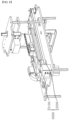
- FIG. 8 is a view of the cartridge conveyance unit 5000 in the automatic immunoassay system according to the present invention.
- the cartridge conveyance unit 5000 includes a cartridge mount 5100 and a cartridge conveyer 5200.
- the cartridge conveyance unit 5000 couples the cartridge unit 2000 to the holding plate 1100 such that the cartridge unit 2000 can be conveyed thereon.
- the cartridge conveyer 5200 conveys the cartridge mount 5100 in the horizontal direction with reference to the holding plate 1100.
- FIG. 9 is a view of the cartridge mount 5100 in the automatic immunoassay system according to the present invention.
- the cartridge mount 5100 includes a first guide bar holding frame 5110, a second guide bar holding frame 5120, a conveyance guide bar 5130, a conveyance frame 5140, and a cartridge mounting plate 5150.
- the first guide bar holding frame 5110 and the second guide bar holding frame 5120 are coupled to opposite ends of the holding plate 1100 with reference to a longitudinal direction of the holding plate 1100, that is, in a direction in which the cartridge unit 2000 is conveyed, respectively.
- the conveyance guide bar 5130 is coupled at opposite ends thereof to the first guide bar holding frame 5110 and the second guide bar holding frame 5120, respectively.
- the conveyance guide bar 5130 may be composed of a single guide bar, the conveyance guide bar is preferably composed of two or more guide bars disposed at both sides of the cartridge unit 2000.
- the conveyance frame 5140 is formed with a guide bar passing hole 5141, through which the conveyance guide bar 5130 passes. Accordingly, as the conveyance guide bar 5130 is inserted into the guide bar passing hole 5141, the conveyance frame 5140 is coupled to the conveyance guide bar 5130 to be moved in the horizontal direction with reference to the conveyance guide bar 5130.
- the cartridge mounting plate 5150 is coupled to an upper portion of the conveyance frame 5140. Accordingly, as the conveyance frame 5140 is conveyed in the horizontal direction with reference to the conveyance guide bar 5130, the cartridge mounting plate 5150 is also conveyed together with the conveyance frame 5140 in the same direction.
- the cartridge unit 2000, the light source unit 3000 and the sensing unit 4000 are coupled to an upper surface of the cartridge mounting plate 5150. Accordingly, as the cartridge mounting plate 5150 is conveyed in the horizontal direction, the cartridge unit 2000, the light source unit 3000 and the sensing unit 4000 are also conveyed in the same direction at the same speed as the cartridge mounting plate 5150.
- FIG. 10 is a view of the cartridge conveyer 5200 in the automatic immunoassay system according to the present invention.
- the cartridge conveyer is coupled to the cartridge mount 5100 to convey the cartridge mount 5100 in the horizontal direction.
- the cartridge conveyer 5200 includes a stepper motor 5210, a rotary block, a timing belt 5230, and a conveyance block 5240.
- the stepper motor 5210 serves to provide drive power for driving the rotary block described below. Referring to FIG. 10 , the stepper motor 5210 is disposed under the holding plate 1100, thereby enabling a compact design of the automatic immunoassay system according to the present invention.
- the rotary block includes a first rotary block 5221 and a second rotary block 5222.
- the first rotary block 5221 and the second rotary block 5222 are coupled to the upper surface of the holding plate 1100, in which the first rotary block 5221 is separated from a side surface of the first guide bar holding frame 5110 and the second rotary block 5222 is separated from a side surface of the second guide bar holding frame 5120.
- each of the first rotary block 5221 and the second rotary block 5222 has a cylindrical shape and is formed in a perpendicular direction with respect to the upper surface of the holding plate 1100.
- the stepper motor 5210 is coupled to the first rotary block 5221 to rotate the first rotary block 5221 in the clockwise direction or in the counterclockwise direction.
- the timing belt 5230 is coupled to outer surfaces of the first rotary block 5221 and the second rotary block 5222 to cooperate therewith. Accordingly, when the stepper motor 5210 is driven, the first rotary block 5221 is rotated to allow the timing belt 5230 engaging with the first rotary block 5221 to be rotated together therewith, and the second rotary block 5222 is also rotated by rotation of the timing belt 5230.
- the second rotary block 5222 assists in rotation of the timing belt 5230 while maintaining tension of the timing belt 5230.
- the outer surfaces of the first rotary block 5221 and the second rotary block 5222 are formed with the same shape of roughness as an inner surface of the timing belt 5230, which engages with the outer surfaces of the first rotary block 5221 and the second rotary block 5222 to allow more efficient transfer of rotating force.
- the conveyance block 5240 is coupled to the timing belt to be conveyed on the timing belt 5230 by rotation of the timing belt 5230.
- the conveyance frame 5140 is rotated together with the timing belt 5230, thereby allowing conveyance of the cartridge unit 2000 in the horizontal direction.
- FIG. 11 is a view of the tip conveyance unit 7000 in the automatic immunoassay system according to the present invention.
- the tip conveyance unit 7000 includes a tip holder 7100, a tip conveyance unit 7200, and a tip vibrator 7300.
- the tip holder 7100 is coupled to an upper surface of the holding plate 1100 and to the tip 6000.
- the tip conveyance unit 7200 conveys the tip 6000 to be dipped in the plurality of wells.
Landscapes
- Health & Medical Sciences (AREA)
- Immunology (AREA)
- Life Sciences & Earth Sciences (AREA)
- Chemical & Material Sciences (AREA)
- Physics & Mathematics (AREA)
- Analytical Chemistry (AREA)
- Biochemistry (AREA)
- General Health & Medical Sciences (AREA)
- General Physics & Mathematics (AREA)
- Pathology (AREA)
- Engineering & Computer Science (AREA)
- Molecular Biology (AREA)
- Biomedical Technology (AREA)
- Urology & Nephrology (AREA)
- Hematology (AREA)
- Microbiology (AREA)
- Food Science & Technology (AREA)
- Biotechnology (AREA)
- Cell Biology (AREA)
- Chemical Kinetics & Catalysis (AREA)
- Medicinal Chemistry (AREA)
- Optics & Photonics (AREA)
- Nuclear Medicine, Radiotherapy & Molecular Imaging (AREA)
- Automatic Analysis And Handling Materials Therefor (AREA)
- Investigating, Analyzing Materials By Fluorescence Or Luminescence (AREA)
- Biophysics (AREA)
- Bioinformatics & Computational Biology (AREA)
- Bioinformatics & Cheminformatics (AREA)
- Proteomics, Peptides & Aminoacids (AREA)
- Peptides Or Proteins (AREA)
Claims (4)
- Système d'immunodosage automatique, comprenant :un boîtier (1000) contenant une plaque de support (1100) ;une unité de cartouche (2000) disposée à l'intérieur du boîtier (1000), raccordée à la plaque de support (1100) et pourvue d'une pluralité de puits ;une unité de source lumineuse (3000) disposée sur un côté de l'unité de cartouche (2000) pour émettre de la lumière vers les puits ;une unité de détection (4000) disposée sur l'autre côté de l'unité de cartouche (2000) pour détecter un signal de fluorescence généré par la lumière émise vers les puits ;une unité de transport de cartouche (5000) raccordée à l'unité de cartouche (2000) et à la plaque de support (1100) et déplaçant l'unité de cartouche (2000) sur la plaque de support (1100) dans un sens horizontal ;une pointe (6000) disposée au-dessus de l'unité de cartouche (2000), plongée séquentiellement dans la pluralité de puits ; etune unité de transport de pointe (7000) raccordée à une surface supérieure de la plaque de support (1100) et déplaçant la pointe (6000) vers le haut et vers le bas,caractérisé en ce que ledit système comprend en outre :une unité d'obturation (8000) disposée entre l'unité de source lumineuse (3000) et les puits pour bloquer la lumière émise par l'unité de source lumineuse (3000) vers les puits ou permettre à la lumière émise par l'unité de source lumineuse (3000) d'atteindre les puits,où l'unité d'obturation (8000) comprend :un corps d'obturateur (8200) disposé entre l'unité de source lumineuse (3000) et les puits pour empêcher la lumière émise par l'unité de source lumineuse (3000) d'atteindre les puits ; etune partie de poussée d'obturateur (8100) raccordée à une partie supérieure de la plaque de support (1100) pour déplacer le corps d'obturateur (8200).
- Système d'immunodosage automatique selon la revendication 1, où l'unité de cartouche (2000) comprend : une cartouche à puits (2100) pourvue de la pluralité de puits ; et un mécanisme de chargement de cartouche (2200) raccordé à une partie inférieure de la cartouche à puits (2100) pour accoupler la cartouche à puits (2100) à la plaque de support (1100).
- Système d'immunodosage automatique selon la revendication 1 ou la revendication 2, où l'unité de transport de cartouche (5000) comprend : un support de cartouche (5100) accouplant l'unité de cartouche (2000) à la plaque de support (1100) ; et un convoyeur de cartouche (5200) transportant le support de cartouche (5100) dans une direction horizontale par rapport à la plaque de support (1100).
- Système d'immunodosage automatique selon l'une des revendications 1 à 3, où l'unité de transport de pointe (7000) comprend : un porte-pointe (7100) retenant la pointe (6000) ; et un convoyeur de pointe (7200) transportant le porte-pointe (7100) vers le haut et vers le bas.
Applications Claiming Priority (1)
| Application Number | Priority Date | Filing Date | Title |
|---|---|---|---|
| KR1020220034923A KR102818381B1 (ko) | 2022-03-21 | 2022-03-21 | 자동 면역분석 시스템 |
Publications (3)
| Publication Number | Publication Date |
|---|---|
| EP4249919A1 EP4249919A1 (fr) | 2023-09-27 |
| EP4249919C0 EP4249919C0 (fr) | 2025-03-05 |
| EP4249919B1 true EP4249919B1 (fr) | 2025-03-05 |
Family
ID=83081968
Family Applications (1)
| Application Number | Title | Priority Date | Filing Date |
|---|---|---|---|
| EP22188739.1A Active EP4249919B1 (fr) | 2022-03-21 | 2022-08-04 | Système d'immunodosage automatique |
Country Status (5)
| Country | Link |
|---|---|
| US (1) | US12467936B2 (fr) |
| EP (1) | EP4249919B1 (fr) |
| JP (1) | JP7616688B2 (fr) |
| KR (1) | KR102818381B1 (fr) |
| CN (1) | CN116819063A (fr) |
Family Cites Families (18)
| Publication number | Priority date | Publication date | Assignee | Title |
|---|---|---|---|---|
| JP2656564B2 (ja) * | 1988-08-26 | 1997-09-24 | 株式会社日立製作所 | 免疫分析方法 |
| JP2844264B2 (ja) * | 1992-07-01 | 1999-01-06 | ベーリング ダイアグノスティックス,インコーポレーテッド | 流体試料保持トレー移送アセンブリを備えた自動化分析器械 |
| JP2000180368A (ja) * | 1998-12-16 | 2000-06-30 | Hitachi Ltd | 化学分析装置 |
| JP2001281259A (ja) * | 2000-03-29 | 2001-10-10 | Sysmex Corp | 液体サンプリング装置 |
| FI20030867A7 (fi) * | 2003-06-10 | 2004-12-11 | Wallac Oy | Optinen mittausmenetelmä ja laboratoriomittauslaite |
| JP2007322245A (ja) * | 2006-05-31 | 2007-12-13 | Olympus Corp | 自動分析装置 |
| JP4964518B2 (ja) * | 2006-06-30 | 2012-07-04 | 株式会社サカエ | 自動分析装置 |
| JP4829716B2 (ja) * | 2006-08-18 | 2011-12-07 | シスメックス株式会社 | 血液凝固分析装置 |
| CN101209515A (zh) * | 2006-12-27 | 2008-07-02 | 富士迈半导体精密工业(上海)有限公司 | 激光切割设备 |
| JP2008281392A (ja) * | 2007-05-09 | 2008-11-20 | Olympus Corp | 測光装置及び自動分析装置 |
| US20130183769A1 (en) * | 2010-09-17 | 2013-07-18 | Universal Bio Research Co., Ltd. | Cartridge and automatic analysis device |
| KR101809645B1 (ko) | 2014-05-30 | 2017-12-15 | 주식회사 이지다이아텍 | 자동 면역분석 수행장치 |
| US11635443B2 (en) * | 2017-07-14 | 2023-04-25 | Meon Medical Solutions Gmbh & Co Kg | Automatic analyzer and method for carrying out chemical, biochemical, and/or immunochemical analyses |
| CN208383715U (zh) * | 2018-05-05 | 2019-01-15 | 哈尔滨索飞永诚科技有限公司 | 一种用于对液体样品中荧光染料染色微粒进行快速计数的计数系统 |
| AT521352B1 (de) * | 2018-07-13 | 2020-01-15 | Meon Medical Solutions Gmbh & Co Kg | Verfahren und vorrichtung zur durchführung von heterogenen immunoassays |
| KR102110197B1 (ko) * | 2018-08-03 | 2020-05-14 | 바디텍메드(주) | 자동화된 액상 면역반응 분석 장치 및 그 방법 |
| KR102102988B1 (ko) * | 2019-03-28 | 2020-04-22 | 주식회사 엘지화학 | 면역 검사 장치 및 면역 검사 방법 |
| KR102204918B1 (ko) * | 2019-07-30 | 2021-01-19 | 피씨엘 주식회사 | 다중 바이오마커 동시 분석 기기 및 다중 바이오마커 동시 분석 방법 |
-
2022
- 2022-03-21 KR KR1020220034923A patent/KR102818381B1/ko active Active
- 2022-08-04 EP EP22188739.1A patent/EP4249919B1/fr active Active
- 2022-08-17 US US17/889,399 patent/US12467936B2/en active Active
- 2022-08-24 CN CN202211015803.5A patent/CN116819063A/zh active Pending
- 2022-09-05 JP JP2022140953A patent/JP7616688B2/ja active Active
Also Published As
| Publication number | Publication date |
|---|---|
| KR102818381B1 (ko) | 2025-06-10 |
| JP2023138899A (ja) | 2023-10-03 |
| EP4249919C0 (fr) | 2025-03-05 |
| US12467936B2 (en) | 2025-11-11 |
| JP7616688B2 (ja) | 2025-01-17 |
| KR20230137141A (ko) | 2023-10-04 |
| US20230296641A1 (en) | 2023-09-21 |
| CN116819063A (zh) | 2023-09-29 |
| EP4249919A1 (fr) | 2023-09-27 |
Similar Documents
| Publication | Publication Date | Title |
|---|---|---|
| JP3521144B2 (ja) | 自動連続ランダム・アクセス分析システムおよびその構成要素 | |
| JP3439466B2 (ja) | 自動連続ランダム・アクセス分析システム及びその構成要素 | |
| JP4012558B2 (ja) | 自動連続ランダムアクセス分析システムおよびその構成要素 | |
| JP3384567B2 (ja) | 自動連続ランダム・アクセス分析システム | |
| CN102753977B (zh) | 化验装置、耗材和方法 | |
| EP0198513A2 (fr) | Procédé analytique et dispositif pour la détermination de fluorescence ou phosphorescence | |
| JP3003118B2 (ja) | ホモジニアス試薬を提供する方法 | |
| JPH06501311A (ja) | 検定または反応装置 | |
| WO2005008255A1 (fr) | Cartouche pour mesure automatique et dispositif de mesure faisant intervenir celle-ci | |
| WO1998018008A1 (fr) | Dispositif d'analyse immunologique automatique | |
| US5904899A (en) | Assaying apparatus and a vessel holder device in use with the assaying apparatus | |
| CN105940306A (zh) | 分析装置 | |
| US5773296A (en) | Bead dispenser and bead dispenser system for immunoassay analysis | |
| JP2005539234A (ja) | 必要な作業の頻度に従ってアッセイを区分化することによって自動臨床アナライザ・システムの処理量を増大させる方法 | |
| CN108139417A (zh) | 容器供给单元及自动分析装置 | |
| JP3991495B2 (ja) | 分析装置 | |
| EP4249919B1 (fr) | Système d'immunodosage automatique | |
| JP2011002340A (ja) | ラック搬送装置及び自動分析装置 | |
| JPH0552854A (ja) | 自動分析装置 | |
| US20080230605A1 (en) | Process and apparatus for maintaining data integrity | |
| JPH06167503A (ja) | 免疫自動分析装置 | |
| JP7661746B2 (ja) | 自動分析装置 | |
| JPH04363667A (ja) | 自動分析装置 | |
| JPH06242119A (ja) | 自動分析装置の検量線補正方法および自動分析装置の検量線補正装置 | |
| WO2023233915A1 (fr) | Dispositif d'inspection |
Legal Events
| Date | Code | Title | Description |
|---|---|---|---|
| PUAI | Public reference made under article 153(3) epc to a published international application that has entered the european phase |
Free format text: ORIGINAL CODE: 0009012 |
|
| STAA | Information on the status of an ep patent application or granted ep patent |
Free format text: STATUS: REQUEST FOR EXAMINATION WAS MADE |
|
| 17P | Request for examination filed |
Effective date: 20220804 |
|
| AK | Designated contracting states |
Kind code of ref document: A1 Designated state(s): AL AT BE BG CH CY CZ DE DK EE ES FI FR GB GR HR HU IE IS IT LI LT LU LV MC MK MT NL NO PL PT RO RS SE SI SK SM TR |
|
| RBV | Designated contracting states (corrected) |
Designated state(s): AL AT BE BG CH CY CZ DE DK EE ES FI FR GB GR HR HU IE IS IT LI LT LU LV MC MK MT NL NO PL PT RO RS SE SI SK SM TR |
|
| GRAP | Despatch of communication of intention to grant a patent |
Free format text: ORIGINAL CODE: EPIDOSNIGR1 |
|
| STAA | Information on the status of an ep patent application or granted ep patent |
Free format text: STATUS: GRANT OF PATENT IS INTENDED |
|
| RIC1 | Information provided on ipc code assigned before grant |
Ipc: G01N 33/53 20060101ALI20241015BHEP Ipc: G01N 21/64 20060101ALI20241015BHEP Ipc: B01L 3/00 20060101ALI20241015BHEP Ipc: G01N 35/02 20060101AFI20241015BHEP |
|
| INTG | Intention to grant announced |
Effective date: 20241023 |
|
| GRAS | Grant fee paid |
Free format text: ORIGINAL CODE: EPIDOSNIGR3 |
|
| GRAA | (expected) grant |
Free format text: ORIGINAL CODE: 0009210 |
|
| STAA | Information on the status of an ep patent application or granted ep patent |
Free format text: STATUS: THE PATENT HAS BEEN GRANTED |
|
| AK | Designated contracting states |
Kind code of ref document: B1 Designated state(s): AL AT BE BG CH CY CZ DE DK EE ES FI FR GB GR HR HU IE IS IT LI LT LU LV MC MK MT NL NO PL PT RO RS SE SI SK SM TR |
|
| REG | Reference to a national code |
Ref country code: GB Ref legal event code: FG4D |
|
| REG | Reference to a national code |
Ref country code: CH Ref legal event code: EP |
|
| REG | Reference to a national code |
Ref country code: IE Ref legal event code: FG4D |
|
| REG | Reference to a national code |
Ref country code: DE Ref legal event code: R096 Ref document number: 602022011350 Country of ref document: DE |
|
| U01 | Request for unitary effect filed |
Effective date: 20250401 |
|
| U07 | Unitary effect registered |
Designated state(s): AT BE BG DE DK EE FI FR IT LT LU LV MT NL PT RO SE SI Effective date: 20250407 |
|
| PG25 | Lapsed in a contracting state [announced via postgrant information from national office to epo] |
Ref country code: RS Free format text: LAPSE BECAUSE OF FAILURE TO SUBMIT A TRANSLATION OF THE DESCRIPTION OR TO PAY THE FEE WITHIN THE PRESCRIBED TIME-LIMIT Effective date: 20250605 |
|
| PG25 | Lapsed in a contracting state [announced via postgrant information from national office to epo] |
Ref country code: ES Free format text: LAPSE BECAUSE OF FAILURE TO SUBMIT A TRANSLATION OF THE DESCRIPTION OR TO PAY THE FEE WITHIN THE PRESCRIBED TIME-LIMIT Effective date: 20250305 |
|
| PG25 | Lapsed in a contracting state [announced via postgrant information from national office to epo] |
Ref country code: NO Free format text: LAPSE BECAUSE OF FAILURE TO SUBMIT A TRANSLATION OF THE DESCRIPTION OR TO PAY THE FEE WITHIN THE PRESCRIBED TIME-LIMIT Effective date: 20250605 |
|
| PG25 | Lapsed in a contracting state [announced via postgrant information from national office to epo] |
Ref country code: HR Free format text: LAPSE BECAUSE OF FAILURE TO SUBMIT A TRANSLATION OF THE DESCRIPTION OR TO PAY THE FEE WITHIN THE PRESCRIBED TIME-LIMIT Effective date: 20250305 |
|
| PG25 | Lapsed in a contracting state [announced via postgrant information from national office to epo] |
Ref country code: GR Free format text: LAPSE BECAUSE OF FAILURE TO SUBMIT A TRANSLATION OF THE DESCRIPTION OR TO PAY THE FEE WITHIN THE PRESCRIBED TIME-LIMIT Effective date: 20250606 |
|
| U20 | Renewal fee for the european patent with unitary effect paid |
Year of fee payment: 4 Effective date: 20250828 |
|
| PG25 | Lapsed in a contracting state [announced via postgrant information from national office to epo] |
Ref country code: SM Free format text: LAPSE BECAUSE OF FAILURE TO SUBMIT A TRANSLATION OF THE DESCRIPTION OR TO PAY THE FEE WITHIN THE PRESCRIBED TIME-LIMIT Effective date: 20250305 |
|
| PG25 | Lapsed in a contracting state [announced via postgrant information from national office to epo] |
Ref country code: PL Free format text: LAPSE BECAUSE OF FAILURE TO SUBMIT A TRANSLATION OF THE DESCRIPTION OR TO PAY THE FEE WITHIN THE PRESCRIBED TIME-LIMIT Effective date: 20250305 |
|
| PG25 | Lapsed in a contracting state [announced via postgrant information from national office to epo] |
Ref country code: CZ Free format text: LAPSE BECAUSE OF FAILURE TO SUBMIT A TRANSLATION OF THE DESCRIPTION OR TO PAY THE FEE WITHIN THE PRESCRIBED TIME-LIMIT Effective date: 20250305 |
|
| PG25 | Lapsed in a contracting state [announced via postgrant information from national office to epo] |
Ref country code: SK Free format text: LAPSE BECAUSE OF FAILURE TO SUBMIT A TRANSLATION OF THE DESCRIPTION OR TO PAY THE FEE WITHIN THE PRESCRIBED TIME-LIMIT Effective date: 20250305 |
|
| PG25 | Lapsed in a contracting state [announced via postgrant information from national office to epo] |
Ref country code: IS Free format text: LAPSE BECAUSE OF FAILURE TO SUBMIT A TRANSLATION OF THE DESCRIPTION OR TO PAY THE FEE WITHIN THE PRESCRIBED TIME-LIMIT Effective date: 20250705 |
|
| PLBE | No opposition filed within time limit |
Free format text: ORIGINAL CODE: 0009261 |
|
| STAA | Information on the status of an ep patent application or granted ep patent |
Free format text: STATUS: NO OPPOSITION FILED WITHIN TIME LIMIT |
|
| REG | Reference to a national code |
Ref country code: CH Ref legal event code: L10 Free format text: ST27 STATUS EVENT CODE: U-0-0-L10-L00 (AS PROVIDED BY THE NATIONAL OFFICE) Effective date: 20260114 |
|
| 26N | No opposition filed |
Effective date: 20251208 |
|
| REG | Reference to a national code |
Ref country code: CH Ref legal event code: H13 Free format text: ST27 STATUS EVENT CODE: U-0-0-H10-H13 (AS PROVIDED BY THE NATIONAL OFFICE) Effective date: 20260324 |
|
| PG25 | Lapsed in a contracting state [announced via postgrant information from national office to epo] |
Ref country code: MC Free format text: LAPSE BECAUSE OF FAILURE TO SUBMIT A TRANSLATION OF THE DESCRIPTION OR TO PAY THE FEE WITHIN THE PRESCRIBED TIME-LIMIT Effective date: 20250305 |