EP4258307A1 - Appareil de technique d'installation domestique - Google Patents
Appareil de technique d'installation domestique Download PDFInfo
- Publication number
- EP4258307A1 EP4258307A1 EP23163085.6A EP23163085A EP4258307A1 EP 4258307 A1 EP4258307 A1 EP 4258307A1 EP 23163085 A EP23163085 A EP 23163085A EP 4258307 A1 EP4258307 A1 EP 4258307A1
- Authority
- EP
- European Patent Office
- Prior art keywords
- rotary knob
- flush
- rotary
- guide element
- guide ring
- Prior art date
- Legal status (The legal status is an assumption and is not a legal conclusion. Google has not performed a legal analysis and makes no representation as to the accuracy of the status listed.)
- Pending
Links
Images


Classifications
-
- H—ELECTRICITY
- H01—ELECTRIC ELEMENTS
- H01H—ELECTRIC SWITCHES; RELAYS; SELECTORS; EMERGENCY PROTECTIVE DEVICES
- H01H19/00—Switches operated by an operating part which is rotatable about a longitudinal axis thereof and which is acted upon directly by a solid body external to the switch, e.g. by a hand
- H01H19/02—Details
- H01H19/025—Light-emitting indicators
-
- H—ELECTRICITY
- H01—ELECTRIC ELEMENTS
- H01H—ELECTRIC SWITCHES; RELAYS; SELECTORS; EMERGENCY PROTECTIVE DEVICES
- H01H19/00—Switches operated by an operating part which is rotatable about a longitudinal axis thereof and which is acted upon directly by a solid body external to the switch, e.g. by a hand
- H01H19/02—Details
- H01H19/10—Movable parts; Contacts mounted thereon
- H01H19/14—Operating parts, e.g. turn knob
-
- H—ELECTRICITY
- H01—ELECTRIC ELEMENTS
- H01H—ELECTRIC SWITCHES; RELAYS; SELECTORS; EMERGENCY PROTECTIVE DEVICES
- H01H3/00—Mechanisms for operating contacts
- H01H3/02—Operating parts, i.e. for operating driving mechanism by a mechanical force external to the switch
- H01H3/08—Turn knobs
- H01H3/10—Means for securing to shaft of driving mechanism
- H01H2003/105—Means for securing to shaft of driving mechanism with compensation of misalignment in the link between the operating part, the driving mechanism and the switch, e.g. misalignment between two axis
-
- H—ELECTRICITY
- H01—ELECTRIC ELEMENTS
- H01H—ELECTRIC SWITCHES; RELAYS; SELECTORS; EMERGENCY PROTECTIVE DEVICES
- H01H2221/00—Actuators
- H01H2221/058—Actuators to avoid tilting or skewing of contact area or actuator
-
- H—ELECTRICITY
- H01—ELECTRIC ELEMENTS
- H01H—ELECTRIC SWITCHES; RELAYS; SELECTORS; EMERGENCY PROTECTIVE DEVICES
- H01H2231/00—Applications
- H01H2231/052—Selectors, e.g. dimmers
Definitions
- the invention relates to a device for domestic installation technology.
- Known devices for home installation technology include rotary switches, room temperature controllers, volume controls and dimmers. These devices are usually flush-mounted devices that are installed in a wall of a house and are operated by rotating a knob via a shaft protruding from a flush-mounted insert. If this device is a dimmer, then in addition to a rotary movement of the rotary knob, an on and off process must be carried out by means of a stroke of the rotary knob.
- the rotary knob mentioned is mounted exclusively on the shaft protruding from the flush-mounted insert by being plugged directly onto the shaft.
- the result of this is that the play of the rotary knob depends exclusively on the play of the shaft protruding from the flush-mounted insert and the rotary knob therefore often exhibits unsatisfactory turning behavior.
- the object of the invention is to provide a domestic installation technology device equipped with a rotary knob, in which the turning behavior of the rotary knob is improved.
- This device for domestic installation technology has a device box, a flush-mounted insert arranged within the device box, a support plate attached to the flush-mounted insert, a rotary knob, a shaft protruding from the flush-mounted insert on which the rotary knob is mounted, a central disk and a Guide element which is designed to guide the rotary knob during its rotational movement.
- the rotary knob has a uniform rotation behavior with a defined and reproducible release torque as well as a rotation behavior that is largely free of play and tilting.
- the guide element is arranged between an inner lateral surface of the rotary knob and a surface of the central disk opposite the inner lateral surface of the rotary knob.
- the guide element is attached to the central disk. This creates a prerequisite for stable and reproducible guidance of the rotary knob during its rotary movement by means of the guide element.
- the guide element is a guide ring arranged between the rotary knob and the central disk. This has the advantage that stable and reproducible guidance of the rotary knob can take place over a large circumferential area of the rotary knob.
- a running surface of the rotary knob slides on an outer surface of the guide ring. This enables a uniform turning behavior of the rotary knob with a defined and reproducible torque as well as a largely play-free and tilt-free turning behavior of the rotary knob.
- the running surface of the rotary knob has ribs. This makes it easier to coordinate between the running surface of the rotary knob and the outer surface of the guide ring.
- the outer surface of the guide ring has ribs. This also makes it easier to coordinate between the running surface of the rotary knob and the outer surface of the guide ring.
- the domestic installation technology device is a rotary switch, a room temperature controller or a volume controller.
- the home installation technology device is a dimmer that has a light source.
- the light source is attached to the carrier plate.
- the light source is a glow lamp.
- the guide element is designed such that the light from the light source is directed into the rotary knob.
- the guide element has light-guiding contours.
- the lower edge region of the rotary knob is designed to be transparent. This achieves an even distribution of light, which enables the viewer to see it from all sides.
- the rotary knob has a transparent slot on its outer casing above the transparent lower edge region, which runs at right angles to the lower edge region, through which the light directed into the rotary knob is visible to the outside. This enables a viewer to recognize the current rotational position of the rotary knob and thus to assess the current brightness.
- the Figure 1 shows a sectional view to illustrate a domestic installation technology device, which is a rotary switch.
- the Figure 2 shows an exploded view in which individual components of the in the Figure 1 Rotary switch shown are shown separately from each other.
- the Figure 3 shows a sketch in which an embodiment of the rotary knob and the guide ring of the rotary switch is illustrated.
- the Figure 4 shows a sectional view to illustrate a home installation technology device, which is a dimmer.
- the Figure 5 shows an exploded view in which individual components of the in the Figure 4 The dimmers shown are shown separately from each other.
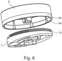
- the Figure 6 shows a sketch in which an embodiment of the rotary knob and the guide ring in the Figure 4 dimmer shown is illustrated.
- the Figure 1 shows a sectional view to illustrate a domestic installation technology device, which is a rotary switch.
- This rotary switch can be arranged in a wall 1 and implemented in the form of a flush-mounted installation device.
- the rotary switch shown has a device socket 2.
- a flush-mounted insert 4 is arranged within this device box, on which a carrier plate 4a is attached. This carrier plate can be screwed, riveted, welded or clamped to the flush-mounted insert.
- the one in the Figure 1 illustrated rotary switch has a rotary knob 6.
- This rotary knob is mounted on a shaft 4b protruding from the flush-mounted insert, preferably clamped to this shaft 4b.
- the one in the Figure 1 illustrated rotary switch has a central disk 5, to which further components of the rotary switch, not shown in detail, are attached.
- the in the Figure 1 Rotary switch shown has a guide element 7, which is designed to guide the rotary knob during its rotary movement.
- this guide element 7 is positioned between an inner surface of the rotary knob 6 and a counter surface of the central disk 5 opposite the inner circumferential surface of the rotary knob and is fastened to this counter surface of the central disk.
- This guide element can be a completely closed guide ring or a guide ring that is closed over a large angular range.
- a running surface of the rotary knob can slide on the outer surface of this guide ring when the rotary knob rotates.
- This tread can be provided in the lower area of the inner surface of the rotary knob.
- Such an arrangement and design enables a uniform rotation behavior of the rotary knob with a defined and reproducible torque as well as a largely play-free and tilt-free rotation behavior of the rotary knob.
- the tread of the rotary knob can be equipped with ribs 6a, as shown in FIG Figure 3 is illustrated. This simplifies the coordination between the running surface of the rotary knob and the outer surface of the guide ring 7.
- the outer surface of the guide ring 7 can also be equipped with ribs. This also simplifies one Coordination between the running surface of the rotary knob and the outer surface of the guide ring.
- Rotary switch shown has a frame 3 and a wing nut 8.
- the Figure 2 shows an exploded view in which individual components of the in the Figure 1 Rotary switch shown are shown separately from each other.
- the flush-mounted insert 4 is firmly connected, for example welded, to the support plate 4a arranged above it using two connecting pieces 4c and 4d. Furthermore, it goes from the Figure 2 shows that the shaft 4b protruding from the flush-mounted insert 4 runs through an inner free space of the carrier plate 4a. Furthermore, in the Figure 2 the frame 3, the central disk 5, the wing nut 8, the guide ring 7 and the rotary knob 6 are shown.
- the guide ring 7 can be designed to be completely closed. Alternatively, the guide ring 7 can also not be designed to be completely closed and have an opening extending over a small angular range in order to simplify the structural coordination between the guide ring 7 and the central disk 5.
- the ones in the Figure 1 Device box 2 shown is in the Figure 2 not shown.
- the Figure 3 shows a sketch in which an embodiment of the rotary knob 6 and the guide ring 7 of the rotary switch is illustrated.
- the running surface of the rotary knob provided in the area of the inner casing of the rotary knob 6 is equipped with ribs 6a in order to improve the coordination between the running surface of the rotary knob 6 and the outer surface of the guide ring 7.
- These ribs 6a can be equidistant in the circumferential direction of the rotary knob in the running surface provided in the area of the inner casing of the rotary knob 6 be arranged to each other, for example offset by 90 ° or 60 ° from each other.
- the guide ring 7 cannot be designed to be completely closed, but can have an opening extending over a small angular range, which is in the Figure 3 is shown on the left side of the guide ring 7.
- the Figure 4 shows a sectional view to illustrate a home installation technology device, which is a dimmer.
- this dimmer can be arranged in a wall 1 and implemented in the form of a flush-mounted installation device.
- the dimmer shown has a device socket 2.
- a flush-mounted insert 4 is arranged within this device box, on which a carrier plate 4a is attached, as in the Figure 5 is illustrated.
- This carrier plate 4a can be screwed, riveted, welded or clamped to the flush-mounted insert 4.
- the one in the Figure 4 illustrated dimmer has a rotary knob 6, which can be composed of two components. This rotary knob is mounted on a shaft 4b protruding from the flush-mounted insert. Furthermore, the one in the Figure 4 illustrated dimmer has a central disk 5, to which further components of the dimmer, not shown in detail, are attached. In addition, the in the Figure 4 Dimmer shown has a guide element 7, which is designed to guide the rotary knob 6 during its rotary movement.
- the guide element 7 is positioned between the rotary knob 6 and the central disk 5 and is attached to it.
- This guide element can be a guide ring on which Outer surface when the rotary knob rotates, a running surface of the rotary knob slides. This enables a uniform turning behavior of the rotary knob with a defined and reproducible torque as well as a largely play-free and tilt-free turning behavior of the rotary knob.
- the running surface of the rotary knob can be equipped with ribs. This allows the coordination between the running surface of the rotary knob and the outer surface of the guide ring to be simplified.
- the outer surface of the guide ring can also be equipped with ribs in order to enable simplified coordination between the running surface of the rotary knob and the outer surface of the guide ring.
- the one in the Figure 4 Dimmer shown has a frame 3 and a wing nut 8.
- the rotary knob 6 is designed in such a way that it can be rotated to change the brightness of the respective room and that it can be subjected to a lifting movement to switch the dimmer on or off.
- the Figure 5 shows an exploded view in which individual components of the in the Figure 4 The dimmers shown are shown separately from each other.
- the flush-mounted insert 4 is firmly connected to the support plate 4a arranged above it. Furthermore, it goes from the Figure 5 shows that the shaft 4b protruding from the flush-mounted insert 4 runs through an inner free space of the carrier plate 4a. Furthermore, in the Figure 5 the frame 3, the central disk 5, the wing nut 8, the guide ring 7 and the rotary knob 6 are shown.
- the dimmer has a light source 9.
- This light source 9 is attached to the carrier plate 4a and arranged decentrally on it.
- the light source 9 is implemented as a glow lamp.
- the light emitted by this glow lamp 9 is emitted upwards through free interior areas of the frame 3 and the central disk 5 and then hits the guide ring 7.
- This is designed in such a way that the light emitted by the glow lamp is directed into the rotary knob 6.
- the guide ring 7 is equipped with light-conducting contours 7a on its outer jacket.
- the lower edge region 6b of the rotary knob 6 is designed to be transparent, so that the light emitted by the glow lamp and directed into the rotary knob is visible from the outside through the transparent lower edge region 6b of the rotary knob when the dimmer is assembled.
- the rotary knob 6 has on its outer casing above the transparent lower edge region 6b a transparent slot 6c arranged at a right angle to the lower edge region 6b, through which the light directed into the rotary knob is also visible from the outside when the dimmer is assembled.
- This light exit through the transparent slot 6c can serve as a visual display for the rotation position of the rotary knob 6 and thus for the brightness of the respective room.
- the Figure 6 shows a sketch in which an embodiment of the rotary knob and the guide ring in the Figure 4 dimmer shown is illustrated. It can be seen that in this embodiment the running surface of the rotary knob provided in the area of the inner casing of the rotary knob 6 is equipped with ribs 6a in order to improve the coordination between the running surface of the rotary knob 6 and the outer surface of the guide ring 7. Furthermore, it is also from the Figure 6 It can be seen that the guide ring 7 is equipped with light-conducting contours 7a on its outer jacket. These are designed in such a way that the lighting parameters of the light emitted by the light source enable all-round perception by a respective observer through a uniform light distribution. The transparently trained also contributes to this lower edge area 6b of the rotary knob 6. The slot 6c in the rotary knob 6, which is also transparent and runs at right angles to the lower edge region 6b, is made of the Figure 6 not apparent.
Landscapes
- Rotary Switch, Piano Key Switch, And Lever Switch (AREA)
- Switch Cases, Indication, And Locking (AREA)
- Mechanical Control Devices (AREA)
Applications Claiming Priority (1)
| Application Number | Priority Date | Filing Date | Title |
|---|---|---|---|
| DE102022108429.9A DE102022108429A1 (de) | 2022-04-07 | 2022-04-07 | Gerät der Hausinstallationstechnik |
Publications (1)
| Publication Number | Publication Date |
|---|---|
| EP4258307A1 true EP4258307A1 (fr) | 2023-10-11 |
Family
ID=85724816
Family Applications (1)
| Application Number | Title | Priority Date | Filing Date |
|---|---|---|---|
| EP23163085.6A Pending EP4258307A1 (fr) | 2022-04-07 | 2023-03-21 | Appareil de technique d'installation domestique |
Country Status (2)
| Country | Link |
|---|---|
| EP (1) | EP4258307A1 (fr) |
| DE (1) | DE102022108429A1 (fr) |
Citations (3)
| Publication number | Priority date | Publication date | Assignee | Title |
|---|---|---|---|---|
| DE3816928A1 (de) * | 1987-05-19 | 1988-12-01 | Alps Electric Co Ltd | Beleuchtungseinrichtung fuer ein elektrisches teil |
| DE202009001286U1 (de) * | 2009-02-03 | 2009-06-25 | Ilchmann, Florian | Universelles LED Steuergerät |
| FR3057989A1 (fr) * | 2016-10-20 | 2018-04-27 | Groupe Brandt | Dispositif de commande manuelle pour un appareil electromenager |
Family Cites Families (3)
| Publication number | Priority date | Publication date | Assignee | Title |
|---|---|---|---|---|
| DE202008010525U1 (de) | 2008-08-07 | 2008-10-16 | Gira Giersiepen Gmbh & Co. Kg | Elektrische Installationsvorrichtung, wie Drehschalter oder Drehregler, insbesondere Rastpotentiometer |
| DE102010009993A1 (de) | 2010-03-02 | 2011-09-08 | Pas Deutschland Gmbh | Blende für ein Haushaltsgerät mit Drehschalter, sowie Haushaltsgerät |
| DE102012222146B4 (de) | 2012-12-04 | 2022-12-08 | BSH Hausgeräte GmbH | Bedienelement für ein Haushaltsgerät mit einem Stützelement und einem Führungselement, Bedienvorrichtung mit einem derartigen Bedienelement sowie Haushaltsgerät mit einer Bedienvorrichtung |
-
2022
- 2022-04-07 DE DE102022108429.9A patent/DE102022108429A1/de active Pending
-
2023
- 2023-03-21 EP EP23163085.6A patent/EP4258307A1/fr active Pending
Patent Citations (3)
| Publication number | Priority date | Publication date | Assignee | Title |
|---|---|---|---|---|
| DE3816928A1 (de) * | 1987-05-19 | 1988-12-01 | Alps Electric Co Ltd | Beleuchtungseinrichtung fuer ein elektrisches teil |
| DE202009001286U1 (de) * | 2009-02-03 | 2009-06-25 | Ilchmann, Florian | Universelles LED Steuergerät |
| FR3057989A1 (fr) * | 2016-10-20 | 2018-04-27 | Groupe Brandt | Dispositif de commande manuelle pour un appareil electromenager |
Also Published As
| Publication number | Publication date |
|---|---|
| DE102022108429A1 (de) | 2023-10-12 |
Similar Documents
| Publication | Publication Date | Title |
|---|---|---|
| DE19964131A1 (de) | Drehknopf mit Tastfunktion | |
| DE202006007047U1 (de) | Vorrichtung zur Beeinflussung eines Lichtstrahls insbesondere zur Bühnenbeleuchtung | |
| DE4041676A1 (de) | Einstellbarer fahrzeugscheinwerfer | |
| DE202008010525U1 (de) | Elektrische Installationsvorrichtung, wie Drehschalter oder Drehregler, insbesondere Rastpotentiometer | |
| DE69010885T2 (de) | Programmanzeige für münz-cd-spieler. | |
| EP2776267A2 (fr) | Dispositif de commande de véhicule | |
| EP2051271A2 (fr) | Actuateur rotatif doté d'un index-repère éclairé et intégré dans une bague rotative | |
| DE20007687U1 (de) | Beleuchtungsvorrichtung | |
| EP4258307A1 (fr) | Appareil de technique d'installation domestique | |
| EP0015525A1 (fr) | Adapteur de connexion électrique en combinaison avec un appareil | |
| DE19542913C2 (de) | Beleuchtbare Bedienelementanordnung | |
| DE60300813T2 (de) | Vorrichtung zm Auswählen und Bestätigen einer Funktion und mit dieser versehenes Armaturenbrett | |
| EP3748234B1 (fr) | Dispositif de commande pour un appareil électrique et procédé de fonctionnement d'un appareil électrique | |
| DE3246985C2 (fr) | ||
| EP2184746B1 (fr) | Appareil de réglage électromécanique doté d'un axe rotatif | |
| DE1665800B2 (de) | Drehschalterantrieb | |
| DE19633892A1 (de) | Drehknopf mit einem integrierten Drucktaster | |
| DE69322055T2 (de) | Ofen mit abnehmbarer von der unteren Ofenwand getrennter Platte | |
| EP2602542B1 (fr) | Dispositif d'éclairage | |
| DE2618114A1 (de) | Vorrichtung zur anzeige der stellung von drehbaren mechanischen elementen | |
| DE2218980B2 (de) | Schalter-Helligkeitsteller-Kombination | |
| DE68928714T2 (de) | Dreh-Antriebseinrichtung eines variablen Widerstandes | |
| DE2238132A1 (de) | Fernsteuerung fuer ein drehbares teil | |
| DE3546625C2 (en) | Electrical rotary switch having illumination | |
| DE3013137A1 (de) | Vorrichtung zur aenderung der einstellung der scheinwerfer an kraftfahrzeugen in abhaengigkeit von der befoerderten last |
Legal Events
| Date | Code | Title | Description |
|---|---|---|---|
| PUAI | Public reference made under article 153(3) epc to a published international application that has entered the european phase |
Free format text: ORIGINAL CODE: 0009012 |
|
| STAA | Information on the status of an ep patent application or granted ep patent |
Free format text: STATUS: THE APPLICATION HAS BEEN PUBLISHED |
|
| AK | Designated contracting states |
Kind code of ref document: A1 Designated state(s): AL AT BE BG CH CY CZ DE DK EE ES FI FR GB GR HR HU IE IS IT LI LT LU LV MC ME MK MT NL NO PL PT RO RS SE SI SK SM TR |
|
| STAA | Information on the status of an ep patent application or granted ep patent |
Free format text: STATUS: REQUEST FOR EXAMINATION WAS MADE |
|
| 17P | Request for examination filed |
Effective date: 20240328 |
|
| RBV | Designated contracting states (corrected) |
Designated state(s): AL AT BE BG CH CY CZ DE DK EE ES FI FR GB GR HR HU IE IS IT LI LT LU LV MC ME MK MT NL NO PL PT RO RS SE SI SK SM TR |
|
| STAA | Information on the status of an ep patent application or granted ep patent |
Free format text: STATUS: EXAMINATION IS IN PROGRESS |
|
| 17Q | First examination report despatched |
Effective date: 20250219 |