EP4261371B1 - Ensemble poignée - Google Patents
Ensemble poignée Download PDFInfo
- Publication number
- EP4261371B1 EP4261371B1 EP22168082.0A EP22168082A EP4261371B1 EP 4261371 B1 EP4261371 B1 EP 4261371B1 EP 22168082 A EP22168082 A EP 22168082A EP 4261371 B1 EP4261371 B1 EP 4261371B1
- Authority
- EP
- European Patent Office
- Prior art keywords
- bridge
- handle
- handle arrangement
- lever
- latch lever
- Prior art date
- Legal status (The legal status is an assumption and is not a legal conclusion. Google has not performed a legal analysis and makes no representation as to the accuracy of the status listed.)
- Active
Links
Images


Classifications
-
- E—FIXED CONSTRUCTIONS
- E05—LOCKS; KEYS; WINDOW OR DOOR FITTINGS; SAFES
- E05B—LOCKS; ACCESSORIES THEREFOR; HANDCUFFS
- E05B77/00—Vehicle locks characterised by special functions or purposes
- E05B77/02—Vehicle locks characterised by special functions or purposes for accident situations
- E05B77/04—Preventing unwanted lock actuation, e.g. unlatching, at the moment of collision
- E05B77/06—Preventing unwanted lock actuation, e.g. unlatching, at the moment of collision by means of inertial forces
-
- E—FIXED CONSTRUCTIONS
- E05—LOCKS; KEYS; WINDOW OR DOOR FITTINGS; SAFES
- E05B—LOCKS; ACCESSORIES THEREFOR; HANDCUFFS
- E05B79/00—Mounting or connecting vehicle locks or parts thereof
- E05B79/10—Connections between movable lock parts
- E05B79/22—Operative connections between handles, sill buttons or lock knobs and the lock unit
-
- E—FIXED CONSTRUCTIONS
- E05—LOCKS; KEYS; WINDOW OR DOOR FITTINGS; SAFES
- E05B—LOCKS; ACCESSORIES THEREFOR; HANDCUFFS
- E05B85/00—Details of vehicle locks not provided for in groups E05B77/00 - E05B83/00
-
- E—FIXED CONSTRUCTIONS
- E05—LOCKS; KEYS; WINDOW OR DOOR FITTINGS; SAFES
- E05B—LOCKS; ACCESSORIES THEREFOR; HANDCUFFS
- E05B85/00—Details of vehicle locks not provided for in groups E05B77/00 - E05B83/00
- E05B85/10—Handles
- E05B85/103—Handles creating a completely closed wing surface
-
- E—FIXED CONSTRUCTIONS
- E05—LOCKS; KEYS; WINDOW OR DOOR FITTINGS; SAFES
- E05B—LOCKS; ACCESSORIES THEREFOR; HANDCUFFS
- E05B85/00—Details of vehicle locks not provided for in groups E05B77/00 - E05B83/00
- E05B85/10—Handles
- E05B85/107—Pop-out handles, e.g. sliding outwardly before rotation
Definitions
- the invention relates to a handle arrangement of a motor vehicle, and particularly to a translational handle arrangement, in particular for a roll-up door, more particularly the invention relates to a flush translational handle arrangement.
- Flush handles of motor vehicles are designed to fit with the surface of the door panel at the rest position, resulting in an improved aerodynamism and a better visual for the user.
- flush handles require an action from the user, like a mechanical input on one end of the handle or an electronic signal, to move from a stowed position to a deployed position wherein the user will be able to grab and pull it to an operative position granting physical access to the vehicle.
- Translational handles are arranged in roll-up doors.
- Said type of handles comprises a front lever and a rear lever cooperating with the two ends of the handle and which both rotate for moving the handle from the stowed position to the deployed position.
- the handle at the deployed position the latter moves to the operative position causing the rear lever to drive in rotation a latch lever pulling a latch cable which unlocks the door latch.
- the door can undesirably be unlatched because of the inertial force resulting from the displacement of the motor vehicle an applied to the handle arrangement mechanism, exposing the user to potential outside injuries.
- the kinematic mechanism chain involved in this system is long, which can result in an undesired actuation of the latch lever.
- the rear lever can undergo torsions during the crash accident resulting in its deformation and an undesired actuation of the latch lever.
- One object of the invention is to provide a more effective system for impairing with undesired unlatching of the door.
- the invention relates to a handle arrangement comprising
- the blocking system of the handle arrangement of the invention is advantageously provided with a bridge that cooperates directly with the latch lever and can block faster a rotation of the latch lever such as preventing the unlatching of a door during a crash accident.
- the inertial rotor comprises a guide cooperating with the actuating arm of the bridge.
- the guide of the inertial rotor is formed by a bent arm configured to push onto the actuating arm of the bridge when the inertial rotor moved from the rest position to the blocking position.
- the actuating arm of the bridge comprises a free end with a finger for cooperating with the wall of the guide of the inertial rotor.
- the inertial rotor comprises a blocking member configured to engage, in the blocking position, the rear lever and prevent its rotation.
- the inertial rotor is maintained in the rest position by a reversible deformable member.
- the bridge extends in parallel to the rear lever.
- the bridge is maintained in the disengaging position by a reversible deformable member.
- the bridge comprises an upper end facing the latch lever and a lower end facing the inertial rotor, the engagement arm extending from the upper end and the actuating arm extending from the lower end.
- the engaging and actuating arms of the bridge extend parallel.
- the bridge further comprises a counterweight disposed oppositely to the extension of actuating arm.
- the bridge comprises a hollow cylindrical core about which the bridge pivots and to which extends the engaging and actuating arms.
- the latch lever comprises a counter-engaging member arranged to cooperate with the engagement arm of the bridge in the engaged position.
- the counter-engaging member is in form of an open mouth with two stoppers extending in different directions.
- the invention relates to a handle arrangement 1 of a motor vehicle, and more particularly to a translational handle arrangement 1.
- the handle arrangement 1 comprises a bracket (not represented) in which are implemented a handle 3, a deploying system 5 of the handle 3, a latch lever 7 for unlatching a door (not represented) and a blocking system 9 for preventing an undesired activation of the latch lever 7.
- Handle 3 is moveable between a stowed position ( Figures 1 and 3 ), a deployed position ( Figures 5 and 6 ) and an operative position ( Figure 9 ) in which handle 3 causes the unlatching of the door via the latch lever 7. More specifically, the operative position of handle 3 triggers the rotation of the latch lever 7 about an axle 8, causing the unlatching of the door.
- the deploying system 5 of the handle 3 comprises two levers, namely a front lever 11 and a rear lever 13, each one being rotatable about a respective double axles mechanism.
- Said double axles mechanisms each comprises a stationary axle 12 about which pivots a movable spindle 15.
- the stationary axles 12 and movable spindles 15 extend parallel to the axles 8.
- the rear lever 13 cooperates with the rear end 17 of the handle 3 and the front lever 11 cooperates with the front end 19 of the handle 3.
- the movement of the rear and front levers (11, 13) may be coordinated by two cross-members 16, each coupled to the movable spindle 15 of both levers (11, 13).
- the deploying system may further comprise a driving system 21 coupled to the front lever 11, as represented in Figure 1 .
- a mechanical or electrical input provided by a user triggers a first tipping of the front and rear levers (11, 13) around the stationary axles 12, moving the handle 3 from the flush position to the deployed position.
- the first tipping may be operated by the driving system 21.
- Handle 3 is then in a position to be grabbed and pulled by the user to unlatch the door, granting physical access to the vehicle.
- Pulling the handle 3 initiates a second tipping of the front and rear levers (11, 13), moving handle 3 from the deployed position to the operative position.
- the second tipping of the rear lever 13 puts it into contact with the latch lever 7 and rotationally drives the latter for unlatching the door.
- the blocking system 9 role is then to impair undesired actuation caused by inertial forces of the latch lever directly and optionally also via the rear lever 13.
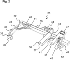
- the blocking system 9 comprises an inertial rotor 23 and a bridge 25 (shown in detail in Figure 2 ).
- the inertial rotor 23 is configured to be driven in rotation about an axle 26 by inertial forces from a rest position ( Figure 3 ) to a preventing position ( Figure 6 ). Such inertial forces may result from a lateral crash accident of the vehicle. Turning to Figure 3 , inertial rotor 23 will be described hereafter in detail.
- the axle 26 of the inertial rotor 23 extends parallel to the axle of the latch lever 7.
- the inertial rotor 23 is maintained in the rest position by the action of a reversible deformable member 27.
- the reversible deformable 27 member may be a spring, like a helicoidal spring.
- the inertial rotor 23 may comprise a blocking member 28 arranged to prevent the tipping of the rear lever 13 in the preventing position.
- This aspect of the invention represents a secondary blocking means for impairing undesired actuation of the latch lever 7, described in more detail below.
- the inertial rotor 23 drives into motion the bridge 25 by means of a driving member 29.
- the driving member 29 may comprise a guide 31 formed by a curved arm.
- the blocking member 28 may be the same member as the driving member 29 or may be part of the driving member 29, as described in detail below.
- Bridge 25 is moveable about a pivot axis 32 between a disengaged position and an engaged position in which it directly blocks the actuation of the latch lever 7.
- This aspect of the invention represents the main blocking means for impairing undesired actuation of the latch lever 7.
- Bridge 25 does not cooperate with the rear lever 13 and directly cooperates with the latch lever 7.
- bridge 25 is independent of the rotational stroke of the rear lever 13 and can act faster than the secondary blocking means against the undesired actuation of the latch lever 7. This reduces the undesired rotational course of the latch lever 7 and improves the prevention of an undesired unlatching of the door.
- Bridge 25 is implemented in the bracket of the handle arrangement 1 by the two free ends of axle 32.
- the said axle 32 may extend parallel to the rear lever 13, and more specifically parallel to the axles 12,15 of the rear lever 13.
- bridge 25 comprises an actuating arm 33 arranged for cooperating with the inertial rotor 23 when the latter moves from the rest position to the preventing position. More specifically, as shown in Figure 3B , the actuating arm 33 comprises a free end 35 for cooperating with the driving member 29 of the inertial rotor 23. The said free end 35 may be provided with a finger 36 extending perpendicularly to the arm 33 and cooperating with guide space 31 of the inertial rotor 23. Cooperation between the inertial rotor 23 and the actuating arm 33 may be seen as pushing on a pedal (here the actuating arm 33), causing the bridge 25 to tilt from the disengaging position to the engaging position.
- a pedal here the actuating arm 33
- the actuating arm 33 may comprise two arms extending parallel and joined by their free end, notably by the finger 36.
- the actuating arm 17 may be formed by a main arm 38 and a reinforcing arm 40 ending into the body of the main arm 25.
- Bridge 25 also comprises an engagement arm 37 arranged for cooperating with the latch lever 7.
- the engagement arm In the disengaging position of bridge 25, the engagement arm is spaced apart from the latch lever 7, letting the latter freely rotate and unlatch the door. Whereas, in the engaging position, the engagement arm 37 comes into contact with the latch lever 7, blocking the rotation of the latter and preventing an undesired unlatching of the door.
- the engagement arm 37 may be a finger, like a straight rigid finger.
- the free end 30 of the engagement arm 37 may be beak-shaped for better cooperation with the latch lever 7, as described in detail below.
- the engagement arm 37 and the actuating arm 33 may extend in the same direction, as represented.
- the actuating arm 33 may extend from an upper end of bridge 25, while the engagement arm 37 may extend from a lower side of bridge 25.
- Bridge 25 may further comprise a hollow cylindrical core 39 wound around the axle 32 and to which extends the engaging and actuating arms (37, 33).
- the fixation of the engaging and actuating arms (37, 33) to the hollow cylindrical core 39 may be strengthened by one more supports 41, especially of a fin-shape.
- the bridge may also comprise a counterweight 43 disposed oppositely to the extension of the actuating arms 33, for counterbalancing the load force exerted by the inertial rotor 23 on the actuating arm 33, when moving from the resting to the preventing position.
- the counterweight 43 may be disposed between the actuating arm 33 and the engagement arm 37 along the axle 32, and more specifically, along with the cylindrical core 39.
- the counterweight 43 may be disposed in a housing 44 extending oppositely to the actuating arm 33 direction. Hence the counterweight 43 and the actuating arm 33 extend on either side of the longitudinal direction of the hollow cylindrical core 31.
- Bridge 25 may be maintained in the disengaging position by a reversible deformable member 45.
- the reversible deformable member 45 may be disposed in a cover 47 notably arranged at the lower end of bridge 25.
- the engagement arm 37 may be disposed in between the actuating arm 33 and the cover 47, as represented in Figure 2 .
- Cover 47 may be L-shaped with two arms extending perpendicularly, namely a holding arm 49, notably extending in direction of the bracket, and a supporting arm 51, notably extending in direction of the push lever 7.
- the reversible deformable member 45 may be arranged to maintain the holding arm 49 of the housing 41 against a part of the bracket in the disengaged position, notably via a resilient bearing 52.
- the reversible deformable member 45 may bear against the supporting arm 51.
- the reversible deformable member 45 may be a spring, and more particularly a helicoidal spring wound around the hollow cylindrical core 39 with one end bearing against the supporting arm 51.
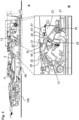
- Figures 3 and 4 represent from two opposite lateral sides handle arrangement 1 wherein handle 3 is in the stowed position. In that position, handle 3 is arranged to be flush with a door panel 100 and a handle frame 66 (see Figures 3A and 4A ) and cannot be grabbed by a user.
- the front lever 11, the rear lever 13, the bridge 25, the inertial rotor 23 and the latch lever 7 are all in a rest position.
- Figure 3B shows in detail the cooperation, in that position, between the rear lever 13, the actuating arm 33 of the bridge 25 and the driving member 29 of the inertial rotor 23.
- the rear lever 13 and the inertial rotor 23 are spaced apart.
- the driving member 29 comprises a curved arm 31 defining a guide space 53 for guiding the actuating arm 33 movement.
- the guide space 53 may have two portions, namely an entrance portion 55 and a deep portion 57, extending in different directions.
- the direction of the entrance portion 55 is configured to rapidly rotatably drive bridge 25 in the engaging position when the inertial rotor 23 undergoes an inertial force and moves from the rest position to the preventing position.
- the direction of the entrance portion 55 crosses the circular direction of the inertial rotor 23 movement (represented by a hash-dotted line).
- the direction of the deep portion 57 is configured to maintain bridge 25 in the engaged position, while the inertial rotor 23 keep tilting to the preventing position. To that end, the direction of the deep portion 57 follows the circular direction of the inertial rotor 23 movement.
- the free end 35, and more particularly the finger 36, of the actuating arm 33 may be disposed in the entrance portion 55 of the guide space 53. This allows better responsiveness of the blocking system 9.
- the inertial rotor 23 comprises a blocking member 28, the latter, in that position, is spaced apart from the rear lever 13.
- FIG 4B shows in detail the cooperation between the rear lever 13, the latch lever 7 and the engagement arm 37 of the bridge 25.
- the rear lever 13 may comprise a driving member 59 for rotationally driving the latch lever 7 by pushing against a push member 61 of the latter.
- the driving member 59 and the push member 61 are, in that position, also spaced apart.
- Figures 5 and 6 represent from two opposite lateral sides handle arrangement 1 wherein handle 3 is in the deployed position.
- the handle 3 has been arrived in that position by a first tipping of the front and rear levers (11, 13) triggered by the user, optionally driven by the driving system 21.
- the handle 3 extends here out of the door panel 100 and the handle frame 66 causing a grabbing part 63 of handle 3 to be made accessible to the user. This enables the user to grab and move handle 3 to the operative position (see Figures 5A and 6A ).
- Figure 5B shows in detail the cooperation, in that position, between the rear lever 13, the actuating arm 33 of the bridge 25 and the driving member 29 of the inertial rotor 23. Since the deployment of the handle has been activated by the user, the blocking system 9 was not triggered. Hence, the inertial rotor 23 and the bridge are in the same position as the one shown in Figure 2 . Meanwhile, the rear lever 13 has tipped to an intermediate position. As showed here, the inertial rotor is sized to not impair, in the rest position, with the tipping of the rear lever 13.
- Figure 6B shows, in that position, the cooperation between the rear lever 13, the latch lever 7 and the engagement arm 37 of the bridge 25. Since bridge 25 and the latch lever 7 have not been activated, they stay in the same position as the one represented in Figure 2 . Meanwhile, because of the first tilting, the driving member 59 of the rear lever 13 has been putting into contact with the push member 61 of the latch lever 7, ready to rotatably drive the latch lever 7.
- Figures 7 and 8 represent the situation when handle arrangement 1 undergoes inertial force which triggers the blocking system.
- the front and the rear lever 11, 13 performed by their own the first tilting, driven by their weight. Consequently, handle 3 moved from the stowed position to a deployed-like position in which it extends out of the door panel 100 and where grabbing part 63 is made accessible. In that situation, although grabbing part 63 is made accessible, actuating the rear lever 13 will not actuate the latch lever 7 as described in detail below.
- Figure 7B shows in detail the cooperation, in that situation, between the rear lever 13, the actuating arm 33 of the bridge 25 and the driving member 29 of the inertial rotor 23.
- the inertial rotor 23 is here in the preventing position, which may be defined as the contact between a supporting member 64 of the inertial rotor 23 and the bracket (not represented).
- the inertial rotor 23 pushed on the free end 35 of the actuating arm 33, causing the latter to move deeper through the guide space 31 to the deep portion 57.
- bridge 25 tilted from the disengaged position to the engaged position.
- the inertial rotor 23 comprises a blocking member 28 for blocking the movement of the rear lever 13.
- the blocking member 28 cooperates with a finger 65 of the rear lever 13.
- the blocking member 28 is an extension part of the driving member 29 and define, together with the free end 67 of the curved arm 31, the entrance portion 55 of the guide space 31 (see also Figure 3B ).
- the free end 67 of the curved arm 31 comes into contact with the finger 65.
- the actuating arm 33 cooperates with the deep portion 57 of the space guide 31, while the finger 65 cooperates with the entrance portion 55 of the space guide 31.
- Figure 8B shows in detail the cooperation, in that situation, between the rear lever 13, the latch lever 7 and the engagement arm 37 of the bridge 25. Because actuation arm 33 tilted, the engagement arm 37 comes into contact with the latch lever 7. Notably, the engagement arm 37 engages a counter-engaging part 69 of the latch lever 7.
- the said counter-engaging part 69 can be in form of an open mouth with two stoppers 71 extending in different directions. Each stopper 17 is provided with a flat surface in contact, in that position, with the engagement arm 37.
- This specific form of the counter-engaging part 69 first allows better cooperation between the engagement arm 37 and the counter-engaging part 69 and secondly decreases, even prevents, failing cooperation between these elements in case of torsions undergone by the bridge 25 during a crash accident.
- the driving member 59 of the rear lever 13 is facing, even in contact with, the push member 61 of the latch lever 7.
- the driving member 59 may push on push member 61, e.g., in case the inertial rotor 23 does not comprise a blocking member 28, this action would not lead to the tilting of the latch lever 7 which is blocked by the contact between the engagement arm 37 and the counter-engaging part 69.
- the inertial rotor 23, the bridge 25, the front and rear lever (11, 13) passively return to their respective rest position by the action of respective reversible deformable members.
- the back movement of the inertial rotor 23 follows the reverse tipping of the rear lever 13 and helps fold down the handle 3 to the stowed position by contact between the blocking member 28 and the finger 65 follows the reverse tipping of the rear lever 13.
- the actuating arm 33 moves back to the entrance portion 55 of the guide space 31, leading bridge 25 to return to the disengaged position.
- Figure 9 shows, in the operative position of the handle 3, the cooperation between the rear lever 13, the latch lever 7 and the engagement arm 37 of the bridge 25.
- This position of handle 3 is triggered by a pull on the grabbing part 63 by the user.
- This causes the driving member 59 of the rear lever 13 to push on the push member 61 of the latch lever 7 and unlatch the door.
- the engagement arm 37 of bridge 23 is sized to not impair, in the disengaged position, with the latch lever 7 rotation.
Landscapes
- Lock And Its Accessories (AREA)
Claims (14)
- Agencement de poignée (1) comprenant :une poignée (3) déplaçable entre une position rangée, une position déployée et une position de fonctionnement dans laquelle la poignée provoque le déverrouillage d'une porte,un levier de verrouillage (7) pour déverrouiller la porte,un système de déploiement (5) accouplé de façon pivotante à la poignée (3) et comprenant un levier avant (11) et un levier arrière (13) coopérant chacun avec une extrémité (17, 19) de la poignée (3), le levier arrière (13) comprenant un élément d'entraînement (59) qui, dans les positions rangée et déployée de la poignée (3), est espacé du levier de verrouillage (7) et, dans la position de fonctionnement de la poignée (3), actionne le levier de verrouillage (7) pour déverrouiller la porte,un système de blocage (9) comprenant un rotor à inertie (23) conçu pour être entraîné en rotation par une force d'inertie d'une position de repos à une position d'empêchement,caractérisé en ce que le système de blocage (9) comprend en outre un pont (25) mobile autour d'un axe de pivotement (32) entre une position hors prise et une position en prise, le pont comprenant un bras de mise en prise (37) qui, dans la position hors prise, est éloigné du levier de verrouillage (7) et, dans la position en prise, entre en prise avec le levier de verrouillage (7) pour empêcher le déverrouillage de la porte, le pont (25) comprenant en outre un bras d'actionnement (33) conçu pour coopérer avec le rotor à inertie (23) lorsque ce dernier se déplace de la position de repos à la position d'empêchement, cette coopération faisant passer le pont (25) de la position hors prise à la position en prise.
- Agencement de poignée (1) selon la revendication 1, le rotor à inertie (23) comprenant un élément d'entraînement (29) coopérant avec le bras d'actionnement (33) du pont (25).
- Agencement de poignée (1) selon la revendication 2, l'élément d'entraînement (29) du rotor à inertie (23) étant formé d'un bras courbe (31) conçu pour pousser sur le bras d'actionnement (33) du pont lorsque le rotor à inertie (23) se déplace de la position de repos à la position de blocage.
- Agencement de poignée (1) selon la revendication 2 ou 3, le bras d'actionnement (33) du pont (23) comprenant une extrémité libre (35) avec un doigt (36) pour coopérer avec l'élément d'entraînement (29) du rotor à inertie (23).
- Agencement de poignée (1) selon l'une quelconque des revendications 1 à 4, le rotor à inertie (23) comprenant un élément de blocage (28) conçu pour entrer en prise, dans la position d'empêchement, avec le levier arrière (13) et empêcher sa rotation.
- Agencement de poignée (1) selon l'une quelconque des revendications 1 à 5, le rotor à inertie (23) étant maintenu dans la position de repos par un élément déformable réversible (27).
- Agencement de poignée (1) selon l'une quelconque des revendications 1 à 6, le pont (23) s'étendant parallèlement au levier arrière (13).
- Agencement de poignée (1) selon l'une quelconque des revendications 1 à 7, le pont (25) étant maintenu dans la position hors prise par un élément déformable réversible (45).
- Agencement de poignée (1) selon l'une quelconque des revendications 1 à 8, le pont (25) comprenant une extrémité inférieure en regard du levier de verrouillage (7) et une extrémité supérieure en regard du rotor à inertie (23), le bras d'actionnement (33) s'étendant à partir de l'extrémité supérieure et le bras de mise en prise (37) s'étendant à partir de l'extrémité inférieure.
- Agencement de poignée (1) selon l'une quelconque des revendications 1 à 9, les bras de mise en prise et d'actionnement (37, 33) du pont (25) s'étendant parallèlement.
- Agencement de poignée (1) selon l'une quelconque des revendications 1 à 10, le pont (25) comprenant en outre un contrepoids (43) disposé à l'opposé de l'étendue du bras d'actionnement (33).
- Agencement de poignée (1) selon l'une quelconque des revendications 1 à 11, le pont comprenant un noyau cylindrique creux autour duquel le pont pivote et jusqu'auquel s'étendent les bras de mise en prise et d'actionnement.
- Agencement de poignée (1) selon l'une quelconque des revendications 1 à 12, le levier de verrouillage (7) comprenant un élément de contre-mise en prise (69) conçu pour coopérer avec le bras de mise en prise (37) du pont (25) dans la position en prise.
- Agencement de poignée (1) selon la revendication 13, l'élément de contre-mise en prise (69) se présentant sous la forme d'une bouche ouverte avec deux éléments de butée (71) s'étendant dans des directions différentes.
Priority Applications (3)
| Application Number | Priority Date | Filing Date | Title |
|---|---|---|---|
| EP22168082.0A EP4261371B1 (fr) | 2022-04-13 | 2022-04-13 | Ensemble poignée |
| US18/179,516 US12467288B2 (en) | 2022-04-13 | 2023-03-07 | Handle arrangement |
| CN202310323882.4A CN116905909A (zh) | 2022-04-13 | 2023-03-29 | 手柄装置 |
Applications Claiming Priority (1)
| Application Number | Priority Date | Filing Date | Title |
|---|---|---|---|
| EP22168082.0A EP4261371B1 (fr) | 2022-04-13 | 2022-04-13 | Ensemble poignée |
Publications (2)
| Publication Number | Publication Date |
|---|---|
| EP4261371A1 EP4261371A1 (fr) | 2023-10-18 |
| EP4261371B1 true EP4261371B1 (fr) | 2024-09-04 |
Family
ID=81308449
Family Applications (1)
| Application Number | Title | Priority Date | Filing Date |
|---|---|---|---|
| EP22168082.0A Active EP4261371B1 (fr) | 2022-04-13 | 2022-04-13 | Ensemble poignée |
Country Status (3)
| Country | Link |
|---|---|
| US (1) | US12467288B2 (fr) |
| EP (1) | EP4261371B1 (fr) |
| CN (1) | CN116905909A (fr) |
Family Cites Families (18)
| Publication number | Priority date | Publication date | Assignee | Title |
|---|---|---|---|---|
| DE102009044042A1 (de) * | 2009-09-17 | 2011-03-24 | Witte-Velbert Gmbh & Co. Kg | Betätigungsvorrichtung mit einem durch Beschleunigungskräfte in eine Blockierstellung bringbaren Blockierglied, insbesondere in Form einer Kraftfahrzeugtürgriffanordnung |
| DE102011115009A1 (de) * | 2010-10-12 | 2012-04-12 | Magna Mirrors Holding Gmbh | Betätigungsvorrichtung für ein Türschloss |
| ITMI20111130A1 (it) * | 2011-06-21 | 2012-12-22 | Valeo Spa | Dispositivo di sicurezza per una maniglia di portiera di veicolo. |
| DE102011051617A1 (de) * | 2011-07-06 | 2013-01-10 | Huf Hülsbeck & Fürst Gmbh & Co. Kg | Sichere Türgriffeinheit |
| DE102012101059A1 (de) * | 2012-02-09 | 2013-08-14 | Huf Hülsbeck & Fürst Gmbh & Co. Kg | Türgriffanordnung für ein Kraftfahrzeug |
| DE102012103154A1 (de) * | 2012-04-12 | 2013-10-17 | Huf Hülsbeck & Fürst Gmbh & Co. Kg | Türgriffanordnung für ein Kraftfahrzeug |
| EP2735676B1 (fr) * | 2012-11-20 | 2017-02-15 | U-Shin Italia S.p.A. | Ensemble de poignée de panneau de véhicule |
| US9567777B1 (en) * | 2012-12-03 | 2017-02-14 | Adac Plastics, Inc. | Inertial blocking member subassembly with negative-acceleration inertial blocking member accelerator |
| EP2942460B1 (fr) * | 2014-05-05 | 2017-09-27 | U-Shin Italia S.p.A. | Système d'activation du verrou de véhicule et véhicule comprenant ce système d'activation |
| DE102017109113A1 (de) * | 2017-04-27 | 2018-10-31 | Huf Hülsbeck & Fürst Gmbh & Co. Kg | Fahrzeugtürgriff |
| EP3556975A1 (fr) * | 2018-04-17 | 2019-10-23 | U-Shin Italia S.p.A. | Ensemble de poignée de porte de véhicule |
| FR3084390B1 (fr) * | 2018-07-27 | 2021-01-01 | U Shin Italia Spa | Poignee d’ouvrant de vehicule automobile munie d’un systeme de securite inertiel |
| JP7050018B2 (ja) * | 2019-02-04 | 2022-04-07 | 株式会社アルファ | 車両のドアハンドル装置 |
| FR3092357B1 (fr) * | 2019-02-05 | 2021-01-08 | Mgi Coutier Espana | Système de poignée de véhicule automobile avec organe de sécurité inertiel. |
| CN110541630B (zh) * | 2019-08-28 | 2021-03-16 | 安徽江淮汽车集团股份有限公司 | 安全把手及其控制方法 |
| JP7313995B2 (ja) | 2019-09-11 | 2023-07-25 | 株式会社アルファ | 車両のハンドル装置 |
| JP7313996B2 (ja) * | 2019-09-11 | 2023-07-25 | 株式会社アルファ | 車両のハンドル装置 |
| KR102751308B1 (ko) * | 2020-08-28 | 2025-01-09 | 현대자동차주식회사 | 차량도어핸들조립체 |
-
2022
- 2022-04-13 EP EP22168082.0A patent/EP4261371B1/fr active Active
-
2023
- 2023-03-07 US US18/179,516 patent/US12467288B2/en active Active
- 2023-03-29 CN CN202310323882.4A patent/CN116905909A/zh active Pending
Also Published As
| Publication number | Publication date |
|---|---|
| EP4261371A1 (fr) | 2023-10-18 |
| CN116905909A (zh) | 2023-10-20 |
| US20230332441A1 (en) | 2023-10-19 |
| US12467288B2 (en) | 2025-11-11 |
Similar Documents
| Publication | Publication Date | Title |
|---|---|---|
| JP7351486B2 (ja) | 格納式ドアハンドルのモータ駆動制御装置及び操作方法 | |
| JP6629724B2 (ja) | ドアハンドルとドアハンドル用の作動装置とから構成されるシステム | |
| JP5811182B2 (ja) | 車両用ドアロック装置 | |
| KR100373242B1 (ko) | 슬라이딩 도어의 록킹콘트롤러 | |
| EP4030022B1 (fr) | Dispositif de poignée pour véhicule | |
| JPS6124631A (ja) | 車両用シ−ト高さ調整装置 | |
| CN118774501A (zh) | 车辆门把手组件 | |
| EP4261371B1 (fr) | Ensemble poignée | |
| CN115071382A (zh) | 滑动门构造 | |
| KR20050047984A (ko) | 도어 열림 방지장치 | |
| JP4345432B2 (ja) | 車両用ドアラッチ機構 | |
| JP3972644B2 (ja) | オーバーヘッドコンソール | |
| US20230358079A1 (en) | Flap system for a handle arrangement | |
| KR100506922B1 (ko) | 슬라이드 도어의 홀드 오픈 록장치 | |
| JP6919487B2 (ja) | 車両のドアロック装置 | |
| JP3636306B2 (ja) | リトラクタブルルーフ | |
| JP4014864B2 (ja) | 自動車のグラブボックスドア | |
| JP7854343B2 (ja) | スロープ装置 | |
| JP2606926B2 (ja) | 自動車のオートステップ装置 | |
| JP7773404B2 (ja) | 車両用ドアロック装置 | |
| JP7815954B2 (ja) | 車両用ドア | |
| KR100457921B1 (ko) | 자동차의 도어 오픈장치 | |
| JPS6092925A (ja) | 自動車用スライドドアの自動開閉装置における操作装置 | |
| JP2001173294A (ja) | オートスライドドアの全開ロック装置 | |
| JP3719248B2 (ja) | 車両用スライドドアの中間位置保持装置 |
Legal Events
| Date | Code | Title | Description |
|---|---|---|---|
| PUAI | Public reference made under article 153(3) epc to a published international application that has entered the european phase |
Free format text: ORIGINAL CODE: 0009012 |
|
| STAA | Information on the status of an ep patent application or granted ep patent |
Free format text: STATUS: THE APPLICATION HAS BEEN PUBLISHED |
|
| AK | Designated contracting states |
Kind code of ref document: A1 Designated state(s): AL AT BE BG CH CY CZ DE DK EE ES FI FR GB GR HR HU IE IS IT LI LT LU LV MC MK MT NL NO PL PT RO RS SE SI SK SM TR |
|
| STAA | Information on the status of an ep patent application or granted ep patent |
Free format text: STATUS: REQUEST FOR EXAMINATION WAS MADE |
|
| 17P | Request for examination filed |
Effective date: 20240216 |
|
| RBV | Designated contracting states (corrected) |
Designated state(s): AL AT BE BG CH CY CZ DE DK EE ES FI FR GB GR HR HU IE IS IT LI LT LU LV MC MK MT NL NO PL PT RO RS SE SI SK SM TR |
|
| RAP3 | Party data changed (applicant data changed or rights of an application transferred) |
Owner name: MINEBEA ACCESSSOLUTIONS ITALIA S.P.A. |
|
| GRAP | Despatch of communication of intention to grant a patent |
Free format text: ORIGINAL CODE: EPIDOSNIGR1 |
|
| STAA | Information on the status of an ep patent application or granted ep patent |
Free format text: STATUS: GRANT OF PATENT IS INTENDED |
|
| RIC1 | Information provided on ipc code assigned before grant |
Ipc: E05B 85/10 20140101ALI20240412BHEP Ipc: E05B 77/06 20140101AFI20240412BHEP |
|
| INTG | Intention to grant announced |
Effective date: 20240507 |
|
| GRAS | Grant fee paid |
Free format text: ORIGINAL CODE: EPIDOSNIGR3 |
|
| GRAA | (expected) grant |
Free format text: ORIGINAL CODE: 0009210 |
|
| STAA | Information on the status of an ep patent application or granted ep patent |
Free format text: STATUS: THE PATENT HAS BEEN GRANTED |
|
| AK | Designated contracting states |
Kind code of ref document: B1 Designated state(s): AL AT BE BG CH CY CZ DE DK EE ES FI FR GB GR HR HU IE IS IT LI LT LU LV MC MK MT NL NO PL PT RO RS SE SI SK SM TR |
|
| REG | Reference to a national code |
Ref country code: GB Ref legal event code: FG4D |
|
| REG | Reference to a national code |
Ref country code: CH Ref legal event code: EP |
|
| REG | Reference to a national code |
Ref country code: IE Ref legal event code: FG4D |
|
| REG | Reference to a national code |
Ref country code: DE Ref legal event code: R096 Ref document number: 602022005786 Country of ref document: DE |
|
| REG | Reference to a national code |
Ref country code: LT Ref legal event code: MG9D |
|
| REG | Reference to a national code |
Ref country code: NL Ref legal event code: MP Effective date: 20240904 |
|
| PG25 | Lapsed in a contracting state [announced via postgrant information from national office to epo] |
Ref country code: NO Free format text: LAPSE BECAUSE OF FAILURE TO SUBMIT A TRANSLATION OF THE DESCRIPTION OR TO PAY THE FEE WITHIN THE PRESCRIBED TIME-LIMIT Effective date: 20241204 |
|
| PG25 | Lapsed in a contracting state [announced via postgrant information from national office to epo] |
Ref country code: PL Free format text: LAPSE BECAUSE OF FAILURE TO SUBMIT A TRANSLATION OF THE DESCRIPTION OR TO PAY THE FEE WITHIN THE PRESCRIBED TIME-LIMIT Effective date: 20240904 Ref country code: GR Free format text: LAPSE BECAUSE OF FAILURE TO SUBMIT A TRANSLATION OF THE DESCRIPTION OR TO PAY THE FEE WITHIN THE PRESCRIBED TIME-LIMIT Effective date: 20241205 Ref country code: FI Free format text: LAPSE BECAUSE OF FAILURE TO SUBMIT A TRANSLATION OF THE DESCRIPTION OR TO PAY THE FEE WITHIN THE PRESCRIBED TIME-LIMIT Effective date: 20240904 |
|
| PG25 | Lapsed in a contracting state [announced via postgrant information from national office to epo] |
Ref country code: BG Free format text: LAPSE BECAUSE OF FAILURE TO SUBMIT A TRANSLATION OF THE DESCRIPTION OR TO PAY THE FEE WITHIN THE PRESCRIBED TIME-LIMIT Effective date: 20240904 |
|
| PG25 | Lapsed in a contracting state [announced via postgrant information from national office to epo] |
Ref country code: LV Free format text: LAPSE BECAUSE OF FAILURE TO SUBMIT A TRANSLATION OF THE DESCRIPTION OR TO PAY THE FEE WITHIN THE PRESCRIBED TIME-LIMIT Effective date: 20240904 |
|
| PG25 | Lapsed in a contracting state [announced via postgrant information from national office to epo] |
Ref country code: HR Free format text: LAPSE BECAUSE OF FAILURE TO SUBMIT A TRANSLATION OF THE DESCRIPTION OR TO PAY THE FEE WITHIN THE PRESCRIBED TIME-LIMIT Effective date: 20240904 |
|
| PG25 | Lapsed in a contracting state [announced via postgrant information from national office to epo] |
Ref country code: RS Free format text: LAPSE BECAUSE OF FAILURE TO SUBMIT A TRANSLATION OF THE DESCRIPTION OR TO PAY THE FEE WITHIN THE PRESCRIBED TIME-LIMIT Effective date: 20241204 Ref country code: ES Free format text: LAPSE BECAUSE OF FAILURE TO SUBMIT A TRANSLATION OF THE DESCRIPTION OR TO PAY THE FEE WITHIN THE PRESCRIBED TIME-LIMIT Effective date: 20240904 |
|
| PG25 | Lapsed in a contracting state [announced via postgrant information from national office to epo] |
Ref country code: RS Free format text: LAPSE BECAUSE OF FAILURE TO SUBMIT A TRANSLATION OF THE DESCRIPTION OR TO PAY THE FEE WITHIN THE PRESCRIBED TIME-LIMIT Effective date: 20241204 Ref country code: PL Free format text: LAPSE BECAUSE OF FAILURE TO SUBMIT A TRANSLATION OF THE DESCRIPTION OR TO PAY THE FEE WITHIN THE PRESCRIBED TIME-LIMIT Effective date: 20240904 Ref country code: NO Free format text: LAPSE BECAUSE OF FAILURE TO SUBMIT A TRANSLATION OF THE DESCRIPTION OR TO PAY THE FEE WITHIN THE PRESCRIBED TIME-LIMIT Effective date: 20241204 Ref country code: LV Free format text: LAPSE BECAUSE OF FAILURE TO SUBMIT A TRANSLATION OF THE DESCRIPTION OR TO PAY THE FEE WITHIN THE PRESCRIBED TIME-LIMIT Effective date: 20240904 Ref country code: HR Free format text: LAPSE BECAUSE OF FAILURE TO SUBMIT A TRANSLATION OF THE DESCRIPTION OR TO PAY THE FEE WITHIN THE PRESCRIBED TIME-LIMIT Effective date: 20240904 Ref country code: GR Free format text: LAPSE BECAUSE OF FAILURE TO SUBMIT A TRANSLATION OF THE DESCRIPTION OR TO PAY THE FEE WITHIN THE PRESCRIBED TIME-LIMIT Effective date: 20241205 Ref country code: FI Free format text: LAPSE BECAUSE OF FAILURE TO SUBMIT A TRANSLATION OF THE DESCRIPTION OR TO PAY THE FEE WITHIN THE PRESCRIBED TIME-LIMIT Effective date: 20240904 Ref country code: ES Free format text: LAPSE BECAUSE OF FAILURE TO SUBMIT A TRANSLATION OF THE DESCRIPTION OR TO PAY THE FEE WITHIN THE PRESCRIBED TIME-LIMIT Effective date: 20240904 Ref country code: BG Free format text: LAPSE BECAUSE OF FAILURE TO SUBMIT A TRANSLATION OF THE DESCRIPTION OR TO PAY THE FEE WITHIN THE PRESCRIBED TIME-LIMIT Effective date: 20240904 |
|
| REG | Reference to a national code |
Ref country code: AT Ref legal event code: MK05 Ref document number: 1720564 Country of ref document: AT Kind code of ref document: T Effective date: 20240904 |
|
| PG25 | Lapsed in a contracting state [announced via postgrant information from national office to epo] |
Ref country code: NL Free format text: LAPSE BECAUSE OF FAILURE TO SUBMIT A TRANSLATION OF THE DESCRIPTION OR TO PAY THE FEE WITHIN THE PRESCRIBED TIME-LIMIT Effective date: 20240904 |
|
| PG25 | Lapsed in a contracting state [announced via postgrant information from national office to epo] |
Ref country code: IS Free format text: LAPSE BECAUSE OF FAILURE TO SUBMIT A TRANSLATION OF THE DESCRIPTION OR TO PAY THE FEE WITHIN THE PRESCRIBED TIME-LIMIT Effective date: 20250104 Ref country code: PT Free format text: LAPSE BECAUSE OF FAILURE TO SUBMIT A TRANSLATION OF THE DESCRIPTION OR TO PAY THE FEE WITHIN THE PRESCRIBED TIME-LIMIT Effective date: 20250106 |
|
| PG25 | Lapsed in a contracting state [announced via postgrant information from national office to epo] |
Ref country code: SM Free format text: LAPSE BECAUSE OF FAILURE TO SUBMIT A TRANSLATION OF THE DESCRIPTION OR TO PAY THE FEE WITHIN THE PRESCRIBED TIME-LIMIT Effective date: 20240904 Ref country code: RO Free format text: LAPSE BECAUSE OF FAILURE TO SUBMIT A TRANSLATION OF THE DESCRIPTION OR TO PAY THE FEE WITHIN THE PRESCRIBED TIME-LIMIT Effective date: 20240904 |
|
| PG25 | Lapsed in a contracting state [announced via postgrant information from national office to epo] |
Ref country code: EE Free format text: LAPSE BECAUSE OF FAILURE TO SUBMIT A TRANSLATION OF THE DESCRIPTION OR TO PAY THE FEE WITHIN THE PRESCRIBED TIME-LIMIT Effective date: 20240904 Ref country code: AT Free format text: LAPSE BECAUSE OF FAILURE TO SUBMIT A TRANSLATION OF THE DESCRIPTION OR TO PAY THE FEE WITHIN THE PRESCRIBED TIME-LIMIT Effective date: 20240904 |
|
| PG25 | Lapsed in a contracting state [announced via postgrant information from national office to epo] |
Ref country code: CZ Free format text: LAPSE BECAUSE OF FAILURE TO SUBMIT A TRANSLATION OF THE DESCRIPTION OR TO PAY THE FEE WITHIN THE PRESCRIBED TIME-LIMIT Effective date: 20240904 |
|
| PG25 | Lapsed in a contracting state [announced via postgrant information from national office to epo] |
Ref country code: IT Free format text: LAPSE BECAUSE OF FAILURE TO SUBMIT A TRANSLATION OF THE DESCRIPTION OR TO PAY THE FEE WITHIN THE PRESCRIBED TIME-LIMIT Effective date: 20240904 Ref country code: SK Free format text: LAPSE BECAUSE OF FAILURE TO SUBMIT A TRANSLATION OF THE DESCRIPTION OR TO PAY THE FEE WITHIN THE PRESCRIBED TIME-LIMIT Effective date: 20240904 |
|
| REG | Reference to a national code |
Ref country code: DE Ref legal event code: R097 Ref document number: 602022005786 Country of ref document: DE |
|
| PGFP | Annual fee paid to national office [announced via postgrant information from national office to epo] |
Ref country code: DE Payment date: 20250411 Year of fee payment: 4 |
|
| PG25 | Lapsed in a contracting state [announced via postgrant information from national office to epo] |
Ref country code: DK Free format text: LAPSE BECAUSE OF FAILURE TO SUBMIT A TRANSLATION OF THE DESCRIPTION OR TO PAY THE FEE WITHIN THE PRESCRIBED TIME-LIMIT Effective date: 20240904 |
|
| PLBE | No opposition filed within time limit |
Free format text: ORIGINAL CODE: 0009261 |
|
| STAA | Information on the status of an ep patent application or granted ep patent |
Free format text: STATUS: NO OPPOSITION FILED WITHIN TIME LIMIT |
|
| 26N | No opposition filed |
Effective date: 20250605 |
|
| PG25 | Lapsed in a contracting state [announced via postgrant information from national office to epo] |
Ref country code: SE Free format text: LAPSE BECAUSE OF FAILURE TO SUBMIT A TRANSLATION OF THE DESCRIPTION OR TO PAY THE FEE WITHIN THE PRESCRIBED TIME-LIMIT Effective date: 20240904 |
|
| REG | Reference to a national code |
Ref country code: CH Ref legal event code: H13 Free format text: ST27 STATUS EVENT CODE: U-0-0-H10-H13 (AS PROVIDED BY THE NATIONAL OFFICE) Effective date: 20251125 |
|
| PG25 | Lapsed in a contracting state [announced via postgrant information from national office to epo] |
Ref country code: LU Free format text: LAPSE BECAUSE OF NON-PAYMENT OF DUE FEES Effective date: 20250413 |
|
| PG25 | Lapsed in a contracting state [announced via postgrant information from national office to epo] |
Ref country code: MC Free format text: LAPSE BECAUSE OF FAILURE TO SUBMIT A TRANSLATION OF THE DESCRIPTION OR TO PAY THE FEE WITHIN THE PRESCRIBED TIME-LIMIT Effective date: 20240904 |
|
| REG | Reference to a national code |
Ref country code: BE Ref legal event code: MM Effective date: 20250430 |
|
| PG25 | Lapsed in a contracting state [announced via postgrant information from national office to epo] |
Ref country code: FR Free format text: LAPSE BECAUSE OF NON-PAYMENT OF DUE FEES Effective date: 20250430 |
|
| PG25 | Lapsed in a contracting state [announced via postgrant information from national office to epo] |
Ref country code: BE Free format text: LAPSE BECAUSE OF NON-PAYMENT OF DUE FEES Effective date: 20250430 |
|
| PG25 | Lapsed in a contracting state [announced via postgrant information from national office to epo] |
Ref country code: CH Free format text: LAPSE BECAUSE OF NON-PAYMENT OF DUE FEES Effective date: 20250430 |
|
| PG25 | Lapsed in a contracting state [announced via postgrant information from national office to epo] |
Ref country code: IE Free format text: LAPSE BECAUSE OF NON-PAYMENT OF DUE FEES Effective date: 20250413 |