EP4268586B1 - Viehstallverteilersystem und ein verfahren zur bereitstellung einer klimaanlage für tiere in einem freistall - Google Patents
Viehstallverteilersystem und ein verfahren zur bereitstellung einer klimaanlage für tiere in einem freistall Download PDFInfo
- Publication number
- EP4268586B1 EP4268586B1 EP22169902.8A EP22169902A EP4268586B1 EP 4268586 B1 EP4268586 B1 EP 4268586B1 EP 22169902 A EP22169902 A EP 22169902A EP 4268586 B1 EP4268586 B1 EP 4268586B1
- Authority
- EP
- European Patent Office
- Prior art keywords
- diverter
- stall
- air
- manifold
- livestock
- Prior art date
- Legal status (The legal status is an assumption and is not a legal conclusion. Google has not performed a legal analysis and makes no representation as to the accuracy of the status listed.)
- Active
Links
Images


Classifications
-
- A—HUMAN NECESSITIES
- A01—AGRICULTURE; FORESTRY; ANIMAL HUSBANDRY; HUNTING; TRAPPING; FISHING
- A01K—ANIMAL HUSBANDRY; AVICULTURE; APICULTURE; PISCICULTURE; FISHING; REARING OR BREEDING ANIMALS, NOT OTHERWISE PROVIDED FOR; NEW BREEDS OF ANIMALS
- A01K1/00—Housing animals; Equipment therefor
- A01K1/0047—Air-conditioning, e.g. ventilation, of animal housings
- A01K1/0052—Arrangement of fans or blowers
-
- A—HUMAN NECESSITIES
- A01—AGRICULTURE; FORESTRY; ANIMAL HUSBANDRY; HUNTING; TRAPPING; FISHING
- A01K—ANIMAL HUSBANDRY; AVICULTURE; APICULTURE; PISCICULTURE; FISHING; REARING OR BREEDING ANIMALS, NOT OTHERWISE PROVIDED FOR; NEW BREEDS OF ANIMALS
- A01K1/00—Housing animals; Equipment therefor
- A01K1/0005—Stable partitions
- A01K1/0011—Cubicle partitions
-
- A—HUMAN NECESSITIES
- A01—AGRICULTURE; FORESTRY; ANIMAL HUSBANDRY; HUNTING; TRAPPING; FISHING
- A01K—ANIMAL HUSBANDRY; AVICULTURE; APICULTURE; PISCICULTURE; FISHING; REARING OR BREEDING ANIMALS, NOT OTHERWISE PROVIDED FOR; NEW BREEDS OF ANIMALS
- A01K1/00—Housing animals; Equipment therefor
- A01K1/0047—Air-conditioning, e.g. ventilation, of animal housings
Definitions
- the present invention relates to a livestock stall diverter system for a free stall stable, said system comprising a plurality of stall dividers arranged in one or more rows comprising at least one vertical support member and at least one diverter member extending away from the support member.
- the invention also relates to a free stall stable and method of providing air conditioning for animals in the free stall stable.
- Such stall diverter systems comprising a plurality of stall dividers positioned side by side are known from e.g. WO 2010/133226A1 .
- Such stall diverter comprises a pair of vertically oriented posts provided in a row with diverter members extending from these posts thereby forming compartments for the animals.
- Other examples of such cattle handling systems for livestock free stalls are known from US 6,467,434 B1 and US 6,318,297 B1 .
- WO 2010/133226A1 provides comfort and welfare for the animals due to bendable and deflectable diverters that reduces the risk of injuring the animals.
- a cow when resting in the compartments are well and then produces more milk, there is still an issue regarding the comfort due to temperature in the stable. This is in particular a problem during summer months and in some warmer regions on the planet. If a cow is experiencing temperatures above approx. 20°C the heat causes discomfort and less production of milk.
- US 3 168 888 A discloses a livestock stall diverter system for a free stall stable, said system comprising a plurality of stall dividers arranged in one or more rows comprising at least one vertical support member and at least one diverter member extending away from the support member.
- US 3 168 888 A also discloses a method of providing air conditioning for animals in a free stall stable.
- a livestock stall diverter system for a free stall stable as defined in claim 1, said system comprising a plurality of stall dividers arranged in one or more rows comprising at least one vertical support member and at least one diverter member extending away from the support member, wherein the at least one diverter member is provided a tubular member with a plurality of air apertures, and that said tubular member is connected to an air supply.
- the at least one tubular member is integrated in the at least one diverter member, which is provided as an elongated tubular member with an inner hollow space and with a plurality of air apertures, and that said hollow space is connected to an air supply.
- the at least one tubular member with a plurality of air apertures is attached to the at least one diverter member and connected to the air supply.
- the invention also concerns a free stall stable comprising a livestock stall diverter system as defined in any one of claims 10 to 14, wherein at least a single row of support posts is provided with diverter members pointing in the same direction and with the manifold provided above said row and providing air supply to the diverter members of the at least one row.
- an air ventilation integrated in the stall diverters so that the animals, in particular cows, can experience a comfortable cooling air breeze when standing or laying down in the compartments in the free stall.
- the airflow through the apertures in the diverter members cools the cows in the vicinity of the diverter members.
- the air is supplied to the inner hollow space of the diverter members with a plurality of air apertures, and that this hollow space is connected to air supply.
- the air is preferably blown or sucked into the barn from the outside and provides a comfortable cooling effect for the cows in the stall compartments between the diverter members as well as a general ventilation of the free stall.
- a plurality of diverter members extend away from the at least one vertical support member.
- the plurality of diverter members comprise an upper diverter member and a lower diverter member, wherein at least the upper diverter member is provided with air apertures.
- the upper diverter and the lower diverter are formed in one piece with a curved distal section or connected to each other by a curved section.
- the stall diverter system comprises at least one crossing member extending perpendicularly to the plurality of diverter members, preferably being arranged on the upper diverter members by being mounted thereon.
- This at least one cross member may also be provided with apertures and connected to the air supply.
- the at least one diverter member and/or the at least one crossing member are provided with a coating of a soft or elastic material, such as rubber, a polymer or the like. This ensures a soft surface texture and thereby increases the comfort of the animals.
- the at least one diverter member, the at least one support member and/or the at least one crossing member may be made of metal tubes, such as galvanised steel. This allows for a cost effective manufacturing of the stall diverter system.
- the at least one diverter member, the at least one support member and/or the at least one cross member may be made of a bendable or deflectable material, such as plastic or glass fibres. This is an inexpensive choice of material and allows for an increase in the comfort and welfare of the animals in the stall diverter system according to the invention.
- the air supply comprises an air supply source and a manifold for supplying air to a plurality of diverter members.
- the manifold is preferably connected to a series of supply tubes for providing fluid communication between the manifold and each of the at least one diverter member.
- the supply tubes may be flexible hoses connected to more rigid connector tubes on the support post and/or he diverter members and/or the crossing members.
- the manifold is advantageously connected to an air supplier, such as a blower, for providing an airflow in the manifold and into the at least one diverter member and out through the apertures therein.
- an air supplier such as a blower
- the manifold is a flexible hose adapted for being mounted above the stall diverters. This arrangement of the air supply system facilitates mounting in a barn house and manufacturing off-site as it allows for compact storage and thereby easy transport to the building where it is to be mounted.
- the air supply source is an air blower or an air suction provider, such as a compressor or an air suction pump, preferably provided outside the barn so that fresh air is drawn into the free stall inside the barn.
- an air blower or an air suction provider such as a compressor or an air suction pump, preferably provided outside the barn so that fresh air is drawn into the free stall inside the barn. This ensures a comfortable air conditioning system for the animals in the stall as well as an air ventilation of the stable.
- the airflow to the animals may be provided by the manifold provided above said one or more rows of stall diverters.
- the manifold is common to at least two rows of stall diverters. This requires less installation components and makes efficient use of the space in the barn above the animals.
- the supplying of air to the manifold may be performed either by blowing air into the manifold or by sucking air into the manifold.
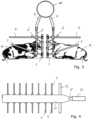
- a first and a second embodiment of a stall diverter system according to the invention, where a single row of compartments are provided in fig. 1 and 7 and in fig. 2 and 6 a second embodiment is shown where two rows of compartments for the animals are provided.
- the stall divider system comprises a vertical support member 1 extending down into the ground or the floor of the stable.
- the vertical support member 1 may alternatively be mounted on a support structure in the ground or floor.
- the support member 1 may be hollow or solid and made of a rigid material such as iron, steel, wood, or similar materials.
- the support member 1 may have any cross-sectional shape, preferably square or circular. The dimensions of the vertical support member 1 may depend on the intended use of the stall dividers, e.g. type and size of the animals.
- a lower member 2 may be mounted on the vertical support member 1 near the ground or the floor. One end of the lower member 2 may be secured to the vertical support member 1 at a certain position using a mounting fixture 3.
- the mounting fixture 3 may have a construction that enables it to be moved up or down on the support member 1.
- the mounting fixture 3 may be attached to the lower member 2 and/or the vertical support member 1 using bolts, screws, or any other type of fastening means.
- the lower member 2 may be mounted directly on the support member 1 using any type of fastening means or by welding or any similar process.
- An upper member 4 may be mounted on the vertical support member 1 at the opposite end.
- the upper member 4 is secured to the vertical support member 1 at a certain position using a mounting fixture 5.
- the mounting fixture 5 may have a construction that enables it to be moved up or down on the support member 1.
- the mounting fixture 5 may be attached to the upper member 4 and/or the vertical support member 1 using bolts, screws, or any other type of fastening means.
- the position of the upper member 5 may be adjusted according to different size animals.
- the mounting fixtures 3, 5 may be identical.
- the lower member 2 extends further than the upper member 4.
- the lower member 2 and/or the upper member 4 may also be moved in the longitudinal direction according to the intended use of the stall dividers and the size of the animals.
- the lower member 2 may extend away from the support member 1 at a predetermined angle relative to the longitudinal direction of the support member.
- the upper member 4 may extend away from the support member 1 at a second predetermined angle (such as substantially perpendicular) relative to the longitudinal direction of the support member.
- the upper member 4 may be angled differently relative to the support member 1, or at the same angle as the lower member 2. This enables the lower and upper members to be placed at optimum angles relative to the size of the animals.
- This crossing member 6 serves the function of a neck rail in the free stall set-up.
- At least the upper member 4 is hollow and made of a tubular material, such as rigid materials such as iron or steel or bendable or deflectable materials such as glass fibre or a polymeric material.
- the lower member 2 is hollow.
- the hollow diverter members 2, 4 are preferably closed at their distal ends, i.e. their ends opposite the mounting fixtures 3, 5.
- At least one of the upper and lower diverter members 2, 4 are provided with apertures 7 (not shown in figures 1 and 2 , see figures 6 and 7 ) so that air can escape from the hollow inner spaces of the tubular members 2, 4 through these apertures.
- the hollow inner spaces of the diverter members 2, 4 are connected to a supply tube 8 which receives air from an air supply and transfer the air via flow connectors 8a and 8b and an intermediate supply tube 8c.
- the crossing member 6 may in some embodiments also be provided with apertures - or tubular members with air apertures - and connected to the air supply.
- the air supply also includes connection hoses 9 that connect the supply tubes 8 to a manifold 10, which as shown in the figures is provided above the row or rows ( fig. 1 and fig. 2 , respectively).
- the manifold 10 is preferably a large hose, which may be mounted hanging from the roof of the barn (not shown) in which the stall diverter system is installed. The manifold 10 is then connected via a hose piece 11 to a blower 12 (see e.g. figures 4 , 5 and 8-10 ).
- the animals 14 will then experience a cooling breeze when they are in a compartment between neighbouring diverter members 2, 4 in the stall diverter system.
- the blower 12 may advantageously be positioned outside of the barn, i.e. on the outside of the exterior wall 13 of the barn. This is advantageous as fresh air can then be delivered into the free stable in the barn and then contribute to the ventilation of the barn and thereby to increase the welfare and comfort of the animals therein.
- FIGS 9 and 10 an example of a stall diverter system installed in a free stable building is shown, where the stall diverters are provided in a single row, such as also shown in e.g. fig. 1 .
- livestock is meant to encompass all types of the domesticated animals raised and/or kept in an agricultural setting to provide labour and produce commodities.
Landscapes
- Life Sciences & Earth Sciences (AREA)
- Environmental Sciences (AREA)
- Zoology (AREA)
- Animal Husbandry (AREA)
- Biodiversity & Conservation Biology (AREA)
- Housing For Livestock And Birds (AREA)
- Ventilation (AREA)
Claims (20)
- Viehstallverteilersystem für einen Freistall, das System umfassend, eine Vielzahl von Stallteilern, die in einer oder mehreren Reihen angeordnet sind und zumindest ein vertikales Stützelement (1) und zumindest ein Umlenkelement umfassen, das sich von dem Stützelement weg erstreckt, dadurch gekennzeichnet, dass das zumindest eine Umlenkelement ein rohrförmiges Element (2, 4) mit einer Vielzahl von Luftöffnungen (7) aufweist und dass das rohrförmige Element mit einer Luftversorgung verbunden ist.
- Viehstallverteilersystem nach Anspruch 1, wobei das zumindest eine rohrförmige Element (2, 4) in das zumindest eine Umlenkelement integriert ist, das als längliches rohrförmiges Element mit einem inneren Hohlraum und mit einer Vielzahl von Luftöffnungen (7) versehen ist, und dass der Hohlraum mit einer Luftversorgung verbunden ist.
- Viehstallverteilersystem nach Anspruch 1 oder 2, wobei sich eine Vielzahl von Umlenkelementen von dem zumindest einen vertikalen Stützelement (1) weg erstreckt.
- Viehstallverteilersystem nach Anspruch 3, wobei die Vielzahl von Umlenkelementen ein oberes Umlenkelement (4) und ein unteres Umlenkelement (2) umfasst, wobei zumindest das obere Umlenkelement mit Luftöffnungen (7) versehen ist.
- Viehstallverteilersystem nach Anspruch 4, wobei der obere Umlenker (4) und der untere Umlenker(2) einstückig mit einem gekrümmten distalen Abschnitt ausgebildet oder durch einen gekrümmten Abschnitt miteinander verbunden sind.
- Viehstallverteilersystem nach einem der vorstehenden Ansprüche, wobei das Stallverteilersystem zumindest ein sich senkrecht zu den mehreren Umlenkelementen erstreckendes Querelement (6) umfasst, das vorzugsweise an den oberen Umlenkelementen angeordnet ist, indem es an diesen befestigt ist.
- Viehstallverteilersystem nach einem der vorstehenden Ansprüche, wobei das zumindest eine Umlenkelement und/oder das zumindest eine Querelement (6) mit einer Beschichtung aus einem weichen oder elastischen Material, wie Gummi, einem Polymer oder dergleichen, versehen ist.
- Viehstallverteilersystem nach einem der vorstehenden Ansprüche, wobei das zumindest eine Umlenkelement, das zumindest eine Stützelement (1) und/oder das zumindest eine Querelement (6) aus Metallrohren, wie beispielsweise verzinktem Stahl, hergestellt sind.
- Viehstallverteilersystem nach einem der Ansprüche 1 - 7, wobei das zumindest eine Umlenkelement, das zumindest eine Stützelement (1) und/oder das zumindest eine Querelement (6) aus einem biegsamen oder biegsamen Material, wie Kunststoff oder Glasfasern, hergestellt sind.
- Viehstallverteilersystem nach einem der vorstehenden Ansprüche, wobei die Luftversorgung eine Luftversorgungsquelle und einen Verteiler (10) zum Zuführen von Luft zu einer Vielzahl von rohrförmigen Elementen der Umlenkelemente umfasst.
- Viehstallverteilersystem nach Anspruch 10, wobei der Verteiler (10) mit einer Reihe von Versorgungsrohren (8) verbunden ist, um eine Fluidverbindung zwischen dem Verteiler (10) und jedem der rohrförmigen Elemente der mehreren Umlenkelemente herzustellen.
- Viehstallverteilersystem nach Anspruch 10 oder 11, wobei der Verteiler (10) mit einem Luftzuführer, wie z. B. einem Gebläse, verbunden ist, um einen Luftstrom in den Verteiler und in das zumindest eine rohrförmige Element des zumindest einen Umlenkelements und durch die darin befindlichen Öffnungen (7) hinaus zu erzeugen.
- Viehstallverteilersystem nach einem der Ansprüche 10 - 12, wobei der Verteiler (10) ein flexibler Schlauch ist, der über den Stallverteilern angebracht werden kann.
- Viehstallverteilersystem nach einem der Ansprüche 10 - 13, wobei die Luftversorgungsquelle ein Luftgebläse (12) oder ein Luftansauger, wie ein Kompressor oder eine Luftansaugpumpe, ist.
- Viehstallverteilersystem nach einem der vorstehenden Ansprüche, wobei das zumindest eine rohrförmige Element mit einer Vielzahl von Luftöffnungen (7) an dem zumindest einen Umlenkelement angebracht und mit der Luftversorgung verbunden ist.
- Freistall, umfassend ein Stallumlenksystem nach einem der Ansprüche 10 bis 14, wobei zumindest eine einzelne Reihe von Stützpfosten (1) mit in die gleiche Richtung weisenden Umlenkelementen versehen ist und wobei der Verteiler (10) oberhalb der Reihe vorgesehen ist und die Luftversorgung der Umlenkelemente der zumindest einen Reihe gewährleistet.
- Freistall nach Anspruch 16, bei dem zumindest zwei Reihen von Stützpfosten (1) mit in entgegengesetzte Richtungen weisenden Umlenkelementen und mit einem gemeinsamen Verteiler (10) versehen sind, der oberhalb der Reihen vorgesehen ist und die Luftversorgung der Umlenkelemente der zumindest zwei Reihen sicherstellt.
- Verfahren zur Klimatisierung von Tieren in einem Freistall, wobei das Verfahren die folgenden Schritte umfasst- Bereitstellen eines Viehstall-Ablenkungssystems, wie ein System nach einem der Ansprüche 1-15, umfassend eine Vielzahl von Stallteilern, die in einer oder mehreren Reihen angeordnet sind und zumindest ein vertikales Stützelement (1) und zumindest ein Umlenkelement umfassen, das sich von dem Stützelement weg erstreckt, wobei das zumindest eine Umlenkelement ein rohrförmiges Element (2, 4) mit einer Vielzahl von Luftöffnungen (7) versehen ist, und dass das rohrförmige Element mit einer Luftversorgung verbunden ist, zum Beispiel wenn das rohrförmige Element in das zumindest eine Umlenkelement eingebaut ist, das als ein längliches rohrförmiges Element mit einem inneren Hohlraum und mit einer Vielzahl von Luftöffnungen versehen ist, und dass der Hohlraum mit der Luftversorgung verbunden ist, und- Bereitstellen eines Luftstroms durch die Öffnungen in dem zumindest einen Umlenkelement durch Bereitstellen eines Verteilers (10), der in Fluidverbindung mit dem Innenraum des zumindest einen Umlenkelements steht, und- Zuführen von Luft zu diesem Verteiler.
- Verfahren nach Anspruch 18, wobei der Luftstrom durch den Verteiler (10) bereitgestellt wird, der oberhalb der einen oder mehreren Reihen von Stallverteilern vorgesehen ist, und wobei der Verteiler vorzugsweise zumindest zwei Reihen von Stallverteilern gemeinsam ist.
- Verfahren nach Anspruch 18 oder 19, wobei das Zuführen von Luft zum Verteiler (10) durch Einblasen von Luft in den Verteiler erfolgt oder wobei das Zuführen von Luft zum Verteiler durch Ansaugen von Luft in den Verteiler erfolgt.
Priority Applications (8)
| Application Number | Priority Date | Filing Date | Title |
|---|---|---|---|
| PL22169902.8T PL4268586T3 (pl) | 2022-04-26 | 2022-04-26 | System rozdzielający stanowiska dla zwierząt gospodarskich i sposób zapewnienia klimatyzacji dla zwierząt w oborze wolnostanowiskowej |
| EP22169902.8A EP4268586B1 (de) | 2022-04-26 | 2022-04-26 | Viehstallverteilersystem und ein verfahren zur bereitstellung einer klimaanlage für tiere in einem freistall |
| ES22169902T ES3006335T3 (en) | 2022-04-26 | 2022-04-26 | A livestock stall diverter system and a method of providing air conditioning for animals in a free stall stable |
| CN202380036609.1A CN119173137A (zh) | 2022-04-26 | 2023-04-20 | 一种牲畜栏舍分流器系统 |
| PCT/EP2023/060240 WO2023208701A1 (en) | 2022-04-26 | 2023-04-20 | A livestock stall diverter system |
| CA3248412A CA3248412A1 (en) | 2022-04-26 | 2023-04-20 | CABIN DEFLECTOR SYSTEM FOR LIVESTOCK |
| US18/857,547 US12550862B2 (en) | 2022-04-26 | 2023-04-20 | Livestock stall diverter system |
| ZA2024/07804A ZA202407804B (en) | 2022-04-26 | 2024-10-15 | A livestock stall diverter system |
Applications Claiming Priority (1)
| Application Number | Priority Date | Filing Date | Title |
|---|---|---|---|
| EP22169902.8A EP4268586B1 (de) | 2022-04-26 | 2022-04-26 | Viehstallverteilersystem und ein verfahren zur bereitstellung einer klimaanlage für tiere in einem freistall |
Publications (3)
| Publication Number | Publication Date |
|---|---|
| EP4268586A1 EP4268586A1 (de) | 2023-11-01 |
| EP4268586B1 true EP4268586B1 (de) | 2024-10-23 |
| EP4268586C0 EP4268586C0 (de) | 2024-10-23 |
Family
ID=81387308
Family Applications (1)
| Application Number | Title | Priority Date | Filing Date |
|---|---|---|---|
| EP22169902.8A Active EP4268586B1 (de) | 2022-04-26 | 2022-04-26 | Viehstallverteilersystem und ein verfahren zur bereitstellung einer klimaanlage für tiere in einem freistall |
Country Status (8)
| Country | Link |
|---|---|
| US (1) | US12550862B2 (de) |
| EP (1) | EP4268586B1 (de) |
| CN (1) | CN119173137A (de) |
| CA (1) | CA3248412A1 (de) |
| ES (1) | ES3006335T3 (de) |
| PL (1) | PL4268586T3 (de) |
| WO (1) | WO2023208701A1 (de) |
| ZA (1) | ZA202407804B (de) |
Families Citing this family (1)
| Publication number | Priority date | Publication date | Assignee | Title |
|---|---|---|---|---|
| EP4442113A1 (de) * | 2023-04-03 | 2024-10-09 | Gary Earls | Belüftete tierstallanordnung |
Family Cites Families (8)
| Publication number | Priority date | Publication date | Assignee | Title |
|---|---|---|---|---|
| US3168888A (en) * | 1962-07-17 | 1965-02-09 | Merrill S Brodrick | Method of feeding dairy cows |
| US6467434B1 (en) | 1999-12-20 | 2002-10-22 | Artex Fabricators Ltd. | Cattle handling system and method of installing same |
| US6318297B1 (en) | 2000-01-26 | 2001-11-20 | John Hatfield | Livestock free stall and method for making the same |
| GB2471707B (en) * | 2009-07-09 | 2014-03-12 | Kingshay Farming And Conservation Ltd | A livestock accomodation divider |
| BR112012006436B1 (pt) | 2009-09-25 | 2019-03-26 | Cow-Welfare A/S | Divisória de baias adequada para estábulos com baias livres, e estábulo com baias livres |
| EP3897111A4 (de) * | 2018-12-17 | 2022-02-23 | Gross, Yehonatan | System und verfahren zum leiten von nutztieren |
| IE87432B1 (en) * | 2021-09-24 | 2023-09-13 | Dairymaster | An animal drafting system |
| EP4447655A1 (de) * | 2021-12-17 | 2024-10-23 | DeLaval Holding AB | Melkanlage und melkverfahren |
-
2022
- 2022-04-26 ES ES22169902T patent/ES3006335T3/es active Active
- 2022-04-26 PL PL22169902.8T patent/PL4268586T3/pl unknown
- 2022-04-26 EP EP22169902.8A patent/EP4268586B1/de active Active
-
2023
- 2023-04-20 CN CN202380036609.1A patent/CN119173137A/zh active Pending
- 2023-04-20 US US18/857,547 patent/US12550862B2/en active Active
- 2023-04-20 WO PCT/EP2023/060240 patent/WO2023208701A1/en not_active Ceased
- 2023-04-20 CA CA3248412A patent/CA3248412A1/en active Pending
-
2024
- 2024-10-15 ZA ZA2024/07804A patent/ZA202407804B/en unknown
Also Published As
| Publication number | Publication date |
|---|---|
| US20250268225A1 (en) | 2025-08-28 |
| US12550862B2 (en) | 2026-02-17 |
| EP4268586A1 (de) | 2023-11-01 |
| CN119173137A (zh) | 2024-12-20 |
| ES3006335T3 (en) | 2025-03-18 |
| WO2023208701A1 (en) | 2023-11-02 |
| CA3248412A1 (en) | 2023-11-02 |
| PL4268586T3 (pl) | 2025-03-10 |
| EP4268586C0 (de) | 2024-10-23 |
| ZA202407804B (en) | 2025-06-25 |
Similar Documents
| Publication | Publication Date | Title |
|---|---|---|
| US6491580B2 (en) | Individual room duct and ventilation system for livestock production building | |
| KR101719772B1 (ko) | 작물 부분 냉난방 시스템 | |
| US12550862B2 (en) | Livestock stall diverter system | |
| Nordlund | Practical considerations for ventilating calf barns in winter | |
| KR20170046884A (ko) | 축사 냉난방 및 냉온음용수 급수 병행 시스템 | |
| US3520244A (en) | Suspension for convection tube | |
| JP2021185759A (ja) | 畜舎の換気システム | |
| CN201624058U (zh) | 一种鸡舍 | |
| KR101568324B1 (ko) | 농축산용 미스트 송풍장치 | |
| EP2304327B1 (de) | Ein ventilationssystem umfassendes gewächshaus | |
| KR102260546B1 (ko) | 분배식 냉온풍 다단 덕트 | |
| EP4442113A1 (de) | Belüftete tierstallanordnung | |
| KR101697293B1 (ko) | 농축산용 미스트 송풍장치의 안내장치 | |
| EP3219201B1 (de) | Belüftungssystem für ein tierproduktionsgebäude, kanalanordnung und verfahren zur zuführung von frischluft in einen raum | |
| KR101572054B1 (ko) | 덕트 열교환 환기 시스템 | |
| KR101521422B1 (ko) | 다수의 결빙 방지 구역에 개별적으로 온풍을 공급하는 온풍기 | |
| CN211064575U (zh) | 一种养牛场用通风降温装置 | |
| JP5008961B2 (ja) | 建屋における室内空気の換気、又は循環装置 | |
| KR200341149Y1 (ko) | 보온시설물용 내부 공기조화장치 | |
| CN215500820U (zh) | 一种双侧进风预热模式的畜禽舍 | |
| US20220330493A1 (en) | System, method and apparatus for creating laminar air flow for indoor growing environments | |
| KR200485884Y1 (ko) | 양돈장 돼지 목 송풍관 | |
| KR102123292B1 (ko) | 축사용 에어커튼장치 | |
| CN209732232U (zh) | 一种鸡舍保温通风装置 | |
| Turnbull | Housing and environment for dairy calves |
Legal Events
| Date | Code | Title | Description |
|---|---|---|---|
| PUAI | Public reference made under article 153(3) epc to a published international application that has entered the european phase |
Free format text: ORIGINAL CODE: 0009012 |
|
| STAA | Information on the status of an ep patent application or granted ep patent |
Free format text: STATUS: THE APPLICATION HAS BEEN PUBLISHED |
|
| AK | Designated contracting states |
Kind code of ref document: A1 Designated state(s): AL AT BE BG CH CY CZ DE DK EE ES FI FR GB GR HR HU IE IS IT LI LT LU LV MC MK MT NL NO PL PT RO RS SE SI SK SM TR |
|
| STAA | Information on the status of an ep patent application or granted ep patent |
Free format text: STATUS: REQUEST FOR EXAMINATION WAS MADE |
|
| 17P | Request for examination filed |
Effective date: 20240410 |
|
| GRAP | Despatch of communication of intention to grant a patent |
Free format text: ORIGINAL CODE: EPIDOSNIGR1 |
|
| RBV | Designated contracting states (corrected) |
Designated state(s): AL AT BE BG CH CY CZ DE DK EE ES FI FR GB GR HR HU IE IS IT LI LT LU LV MC MK MT NL NO PL PT RO RS SE SI SK SM TR |
|
| STAA | Information on the status of an ep patent application or granted ep patent |
Free format text: STATUS: GRANT OF PATENT IS INTENDED |
|
| INTG | Intention to grant announced |
Effective date: 20240516 |
|
| GRAS | Grant fee paid |
Free format text: ORIGINAL CODE: EPIDOSNIGR3 |
|
| GRAA | (expected) grant |
Free format text: ORIGINAL CODE: 0009210 |
|
| STAA | Information on the status of an ep patent application or granted ep patent |
Free format text: STATUS: THE PATENT HAS BEEN GRANTED |
|
| AK | Designated contracting states |
Kind code of ref document: B1 Designated state(s): AL AT BE BG CH CY CZ DE DK EE ES FI FR GB GR HR HU IE IS IT LI LT LU LV MC MK MT NL NO PL PT RO RS SE SI SK SM TR |
|
| REG | Reference to a national code |
Ref country code: GB Ref legal event code: FG4D |
|
| REG | Reference to a national code |
Ref country code: CH Ref legal event code: EP |
|
| REG | Reference to a national code |
Ref country code: DE Ref legal event code: R096 Ref document number: 602022006976 Country of ref document: DE |
|
| REG | Reference to a national code |
Ref country code: IE Ref legal event code: FG4D |
|
| U01 | Request for unitary effect filed |
Effective date: 20241119 |
|
| U07 | Unitary effect registered |
Designated state(s): AT BE BG DE DK EE FI FR IT LT LU LV MT NL PT RO SE SI Effective date: 20241125 |
|
| REG | Reference to a national code |
Ref country code: ES Ref legal event code: FG2A Ref document number: 3006335 Country of ref document: ES Kind code of ref document: T3 Effective date: 20250318 |
|
| PG25 | Lapsed in a contracting state [announced via postgrant information from national office to epo] |
Ref country code: IS Free format text: LAPSE BECAUSE OF FAILURE TO SUBMIT A TRANSLATION OF THE DESCRIPTION OR TO PAY THE FEE WITHIN THE PRESCRIBED TIME-LIMIT Effective date: 20250223 Ref country code: HR Free format text: LAPSE BECAUSE OF FAILURE TO SUBMIT A TRANSLATION OF THE DESCRIPTION OR TO PAY THE FEE WITHIN THE PRESCRIBED TIME-LIMIT Effective date: 20241023 |
|
| PG25 | Lapsed in a contracting state [announced via postgrant information from national office to epo] |
Ref country code: NO Free format text: LAPSE BECAUSE OF FAILURE TO SUBMIT A TRANSLATION OF THE DESCRIPTION OR TO PAY THE FEE WITHIN THE PRESCRIBED TIME-LIMIT Effective date: 20250123 |
|
| PG25 | Lapsed in a contracting state [announced via postgrant information from national office to epo] |
Ref country code: GR Free format text: LAPSE BECAUSE OF FAILURE TO SUBMIT A TRANSLATION OF THE DESCRIPTION OR TO PAY THE FEE WITHIN THE PRESCRIBED TIME-LIMIT Effective date: 20250124 |
|
| PG25 | Lapsed in a contracting state [announced via postgrant information from national office to epo] |
Ref country code: RS Free format text: LAPSE BECAUSE OF FAILURE TO SUBMIT A TRANSLATION OF THE DESCRIPTION OR TO PAY THE FEE WITHIN THE PRESCRIBED TIME-LIMIT Effective date: 20250123 |
|
| U20 | Renewal fee for the european patent with unitary effect paid |
Year of fee payment: 4 Effective date: 20250425 |
|
| PG25 | Lapsed in a contracting state [announced via postgrant information from national office to epo] |
Ref country code: SM Free format text: LAPSE BECAUSE OF FAILURE TO SUBMIT A TRANSLATION OF THE DESCRIPTION OR TO PAY THE FEE WITHIN THE PRESCRIBED TIME-LIMIT Effective date: 20241023 |
|
| PGFP | Annual fee paid to national office [announced via postgrant information from national office to epo] |
Ref country code: PL Payment date: 20250418 Year of fee payment: 4 |
|
| PGFP | Annual fee paid to national office [announced via postgrant information from national office to epo] |
Ref country code: ES Payment date: 20250530 Year of fee payment: 4 |
|
| PGFP | Annual fee paid to national office [announced via postgrant information from national office to epo] |
Ref country code: CH Payment date: 20250501 Year of fee payment: 4 |
|
| PG25 | Lapsed in a contracting state [announced via postgrant information from national office to epo] |
Ref country code: SK Free format text: LAPSE BECAUSE OF FAILURE TO SUBMIT A TRANSLATION OF THE DESCRIPTION OR TO PAY THE FEE WITHIN THE PRESCRIBED TIME-LIMIT Effective date: 20241023 |
|
| PGFP | Annual fee paid to national office [announced via postgrant information from national office to epo] |
Ref country code: TR Payment date: 20250421 Year of fee payment: 4 |
|
| PG25 | Lapsed in a contracting state [announced via postgrant information from national office to epo] |
Ref country code: CZ Free format text: LAPSE BECAUSE OF FAILURE TO SUBMIT A TRANSLATION OF THE DESCRIPTION OR TO PAY THE FEE WITHIN THE PRESCRIBED TIME-LIMIT Effective date: 20241023 |
|
| PGFP | Annual fee paid to national office [announced via postgrant information from national office to epo] |
Ref country code: IE Payment date: 20250422 Year of fee payment: 4 |
|
| PLBE | No opposition filed within time limit |
Free format text: ORIGINAL CODE: 0009261 |
|
| STAA | Information on the status of an ep patent application or granted ep patent |
Free format text: STATUS: NO OPPOSITION FILED WITHIN TIME LIMIT |
|
| 26N | No opposition filed |
Effective date: 20250724 |
|
| PG25 | Lapsed in a contracting state [announced via postgrant information from national office to epo] |
Ref country code: MC Free format text: LAPSE BECAUSE OF FAILURE TO SUBMIT A TRANSLATION OF THE DESCRIPTION OR TO PAY THE FEE WITHIN THE PRESCRIBED TIME-LIMIT Effective date: 20241023 |