EP4270689A1 - Dispositif éclateur - Google Patents
Dispositif éclateur Download PDFInfo
- Publication number
- EP4270689A1 EP4270689A1 EP23168906.8A EP23168906A EP4270689A1 EP 4270689 A1 EP4270689 A1 EP 4270689A1 EP 23168906 A EP23168906 A EP 23168906A EP 4270689 A1 EP4270689 A1 EP 4270689A1
- Authority
- EP
- European Patent Office
- Prior art keywords
- holding frame
- spark gap
- holding
- electrode
- gap arrangement
- Prior art date
- Legal status (The legal status is an assumption and is not a legal conclusion. Google has not performed a legal analysis and makes no representation as to the accuracy of the status listed.)
- Granted
Links
Images



Classifications
-
- H—ELECTRICITY
- H01—ELECTRIC ELEMENTS
- H01T—SPARK GAPS; OVERVOLTAGE ARRESTERS USING SPARK GAPS; SPARKING PLUGS; CORONA DEVICES; GENERATING IONS TO BE INTRODUCED INTO NON-ENCLOSED GASES
- H01T4/00—Overvoltage arresters using spark gaps
- H01T4/16—Overvoltage arresters using spark gaps having a plurality of gaps arranged in series
-
- H—ELECTRICITY
- H01—ELECTRIC ELEMENTS
- H01T—SPARK GAPS; OVERVOLTAGE ARRESTERS USING SPARK GAPS; SPARKING PLUGS; CORONA DEVICES; GENERATING IONS TO BE INTRODUCED INTO NON-ENCLOSED GASES
- H01T4/00—Overvoltage arresters using spark gaps
- H01T4/02—Details
-
- H—ELECTRICITY
- H01—ELECTRIC ELEMENTS
- H01T—SPARK GAPS; OVERVOLTAGE ARRESTERS USING SPARK GAPS; SPARKING PLUGS; CORONA DEVICES; GENERATING IONS TO BE INTRODUCED INTO NON-ENCLOSED GASES
- H01T4/00—Overvoltage arresters using spark gaps
- H01T4/16—Overvoltage arresters using spark gaps having a plurality of gaps arranged in series
- H01T4/18—Arrangements for reducing height of stacked spark gaps
-
- H—ELECTRICITY
- H01—ELECTRIC ELEMENTS
- H01T—SPARK GAPS; OVERVOLTAGE ARRESTERS USING SPARK GAPS; SPARKING PLUGS; CORONA DEVICES; GENERATING IONS TO BE INTRODUCED INTO NON-ENCLOSED GASES
- H01T1/00—Details of spark gaps
-
- H—ELECTRICITY
- H01—ELECTRIC ELEMENTS
- H01T—SPARK GAPS; OVERVOLTAGE ARRESTERS USING SPARK GAPS; SPARKING PLUGS; CORONA DEVICES; GENERATING IONS TO BE INTRODUCED INTO NON-ENCLOSED GASES
- H01T4/00—Overvoltage arresters using spark gaps
- H01T4/16—Overvoltage arresters using spark gaps having a plurality of gaps arranged in series
- H01T4/20—Arrangements for improving potential distribution
Definitions
- the invention relates to a spark gap arrangement with at least three electrodes and with at least two holding frames which are arranged flat one above the other, the holding frames each having an edge which surrounds a recess for receiving at least one electrode.
- the invention also relates to a holding frame for such a spark gap arrangement.
- a variety of surge protection devices are known from the prior art and are used to protect electrical devices or lines from surges that can be caused, for example, by lightning strikes or defects in technical systems. Spark gap arrangements with multiple electrodes have been used for decades in the area of overvoltage protection in electrical devices and systems. In order to dissipate high overvoltages while at the same time ensuring a high mains follow current extinguishing capacity, multiple spark gaps are often used, which are often referred to as stacked spark gaps due to their structure. Such stacked spark gaps consist of several electrodes and several insulations, which are arranged between the individual electrodes, so that there is insulation between two electrodes, which has an opening in the middle, so that two electrodes form a spark gap.
- the electrodes are generally designed as circular or rectangular graphite disks, between which corresponding ring-shaped or frame-like insulation is then arranged.
- the insulations are often designed as thin insulation films made of plastic, for example PTFE, and are generally less than 1 mm thick.
- a stacking spark gap is known in which the installation space or space requirement is reduced by the fact that the individual electrodes are perforated in the middle and the contact plates arranged on the end faces of the stacked electrodes are connected to one another by a guide rod, which perforates the individual electrodes and the perforations of the ring-shaped insulation passes through.
- the DE 10 2016 114 787 A1 discloses a carrier unit for spark gaps that can be connected and stacked in series, which consists of an insulating body that has a recess for the electrode.
- the insulating body is designed such that it accommodates a single electrode, with several insulating bodies then being stacked one on top of the other.
- a radial opening is additionally formed in the insulating body, which is connected to the receptacle for the electrode, so that the electrode can be contacted through the opening on its radial outer surface.
- the DE 10 2011 102 864 A1 discloses a stacked spark gap with several individual spark gaps connected in series, with the individual electrodes each being arranged in an insulating body.
- the insulating bodies each have a recess for receiving a disk-shaped electrode and a receptacle for a control element, the receptacle for the control element being connected to the recess for the electrode.
- a control element is connected to the edge of the electrode via a contact spring, so that triggering of the individual electrodes of the stack spark gap can be achieved via the control elements.
- the DE 10 2018 118 898 B3 discloses a holding arrangement for several electrodes, which consists of at least two holding frames that can be stacked flat on top of each other.
- the individual holding frames In the individual holding frames, three recesses are formed next to each other to accommodate one electrode per recess, so that three stacking spark gaps arranged next to one another can be realized by stacking several such holding frames on top of one another.
- a corresponding number of openings connected to the recesses are formed in the individual holding frames, through which the outer surfaces of the individual electrodes can be contacted. The openings are formed on one long side of the holding frame, so that the individual electrodes can be contacted from this side.
- stacked spark gaps are known from the prior art, in which the individual electrodes are each arranged in a frame-shaped insulating body.
- the individual disc-shaped electrodes are contacted on their narrow side, i.e. on their outer surface arranged in the longitudinal extent of the stacked spark gap.
- the present invention is therefore based on the object of providing a spark gap arrangement which enables contacting of the individual electrodes even when using particularly narrow electrodes.
- a holding frame should be provided that can be used in such a spark gap arrangement.
- At least one receiving opening is formed in the edge of at least one holding frame, in which a control element is arranged.
- the individual holding frames are arranged twisted relative to one another about their central axis M, which is arranged perpendicular to the plane of the holding frame, in such a way that the receiving opening of a first holding frame is located above an electrode which is accommodated in a second holding frame arranged underneath is.
- the spark gap arrangement preferably consists of several electrodes and accordingly also of several holding frames, so that the spark gap arrangement is a multiple spark gap or stacked spark gap.
- the individual holding frames - and with them the electrodes accommodated in them - are then arranged as a stack mounted twisted around the center.
- the at least one receiving opening in the holding frame is arranged near a corner of the holding frame.
- the arrangement of the receiving opening near a corner of the holding frame makes it possible for the angle by which the individual holding frames arranged one above the other must be arranged twisted relative to one another to be relatively small.
- the individual holding frames are each arranged twisted relative to one another to such an extent that the electrode arranged underneath can be contacted in the area of a corner by a control element arranged in a receiving opening.
- angles of rotation of less than 15°, in particular less than 10°, for example 7.5°, may be sufficient.
- the individual holding frames each have a collar-shaped support section directed inwards towards the central axis M, against which at least one electrode comes into contact.
- the electrodes are therefore not held in their position, at least not only by the edge of the holding frame surrounding the recess, even if the recesses are adapted to the outer dimensions of the electrodes, but also by the fact that the edge of the electrodes rests on the collar-shaped support section of the on the holding frame.
- the support section is opposite the edge of the Holding frame is set back in the direction of the central axis M. An electrode can come into contact on both sides of the collar-shaped support section.
- the collar-shaped support section also takes on the function of the insulation foils between the individual electrodes, which are otherwise often used in stacking spark gaps.
- the individual electrodes By placing the individual electrodes on the support section of the respective holding frame, two electrodes that are at least partially accommodated by a holding frame thus have a defined distance from one another, which is predetermined by the thickness of the support section.
- a spark gap arrangement can be realized which has very small dimensions, in particular in the longitudinal extent of the spark gap arrangement or the stacked spark gap.
- a spark gap arrangement has two holding frames, a total of three electrodes can be accommodated by the two holding frames, with the middle electrode being arranged between the two holding frames and thus being held together by both holding frames.
- the two outer electrodes on the other hand, only have one end face, the front or the back, resting on a support section of a holding frame, while the other end face is electrically contacted by a contact plate and held in the holding frame.
- a spark gap arrangement with n holding frames can therefore accommodate n + 1 electrodes. Since the two outer electrodes can each be contacted via a contact plate, n - 1 control elements can be provided in such a spark gap arrangement, which correspondingly contact n - 1 electrodes.
- the holding frames can have an approximately rectangular shape. However, this does not exclude the possibility that the holding frames have an outer contour and an inner contour, each of which deviates from that of a rectangle.
- the outer contour of the holding frame, which deviates from a rectangle, can be used in particular to provide space for the arrangement of the receiving opening for the control element in the edge of the holding frame.
- the edge of the holding frame can have a section that projects outwards, in which case the receiving opening for the control element is formed in the area of the section.
- the inner contour of the holding frame is determined by the inner edge of the support section.
- the collar-shaped support section can have an octagonal inner edge, with individual inner angles being able to have different values. If, in the spark gap arrangement according to the invention, two holding frames are arranged rotated relative to one another by an angle ⁇ , it is preferably provided that four internal angles ⁇ 1 have a value of 90° + ⁇ and four internal angles ⁇ 2 have a value of 180° - ⁇ . The different interior angles ⁇ 1 and ⁇ 2 are arranged or formed alternately relative to one another in the circumferential direction.
- the specific shape of the holding frame in particular its inner contour, is therefore designed depending on the angle at which individual holding frames are arranged twisted relative to one another or the angle of rotation between the individual holding frames depends on the specific shape of the holding frame .
- the individual holding frames are designed such that they are locked in their mutually twisted arrangement. This also simplifies the positioning of the individual holding frames relative to one another and ensures that the position of the individual holding frames relative to one another, in particular the angle by which adjacent holding frames are rotated relative to one another, does not unintentionally change again during assembly of the spark gap arrangement.
- the holding frames can each have at least one locking element on at least one side, with two locking elements of two holding frames interacting when the two holding frames are stacked one above the other in the intended, mutually twisted arrangement.
- the holding frames can each have at least one latching element on the front and a counter-latching element on the back, the latching element of a holding frame engaging in a counter-latching element of a second holding frame when the two holding frames are stacked one above the other, twisted relative to one another by the intended angle ⁇ are.
- pin-shaped pins and corresponding pin holes as counter-locking elements can be provided as locking elements.
- the individual electrodes of the spark gap arrangement are preferably designed as rectangular, in particular square, thin disks made of graphite or a tungsten-copper composite material.
- the thickness of the electrode disks can be less than 5 mm, in particular less than 3 mm.
- the task mentioned at the beginning is achieved in a holding frame for a corresponding spark gap arrangement with the features of patent claim 9.
- the holding frame has an edge which surrounds a recess for receiving an electrode, the recess being adapted to the external dimensions of the electrode. According to the invention it is provided that at least one receiving opening is formed in the edge of the holding frame for receiving a control element.
- the holding frame preferably has a collar-shaped support section for at least one electrode directed inwards towards the central axis M of the holding frame, the support section preferably being set back relative to the edge of the holding frame in the direction of the central axis M.
- the outer contour and the inner contour of the holding frame are preferably designed in such a way that they deviate from that of a rectangle, with the collar-shaped support section in particular having an octagonal inner edge.
- the inner edge preferably does not correspond to a regular octagon, with eight interior angles ⁇ of equal size. Rather, the inner edge preferably has four internal angles ⁇ 1 and four internal angles ⁇ 2 , which are arranged alternately with one another.
- the interior angle ⁇ 1 is 90° + ⁇ and the interior angle ⁇ 2 is 180° - ⁇ .
- the holding frame can consist of a plastic or a ceramic material and have a relatively small thickness of preferably less than 10 mm, in particular less than 5 mm. In principle, however, other insulating materials for the holding frame and other dimensions, in particular other thicknesses, are also possible.
- the figures show a spark gap arrangement 1 or electrodes 2 and holding frame 3 for a spark gap arrangement 1, each holding frame 3 being able to partially accommodate two electrodes 2.
- a spark gap arrangement 1 consists of at least three electrodes 2 and at least two holding frames 3 that accommodate the electrodes 2, the holding frames 3 being arranged flat one above the other. Even if in Fig. 1 only three holding frames 3 are shown, the number of holding frames 3 and thus also the number of electrodes 2, which are part of the spark gap arrangement 1, is not limited to this, but a spark gap arrangement 1 can also have significantly more electrodes 2 and thus also significantly more holding frames 3 have.
- a spark gap arrangement 1 with n holding frames 3 can accommodate a total of n - 1 electrodes 2.
- FIG. 1 An exploded view of such a spark gap arrangement 1 is in Fig. 1 shown.
- the spark gap arrangement shown consists of three holding frames 3, 3 ', 3 "and four electrodes 2, of which, however, only three electrodes 2 are visible.
- the middle holding frame 3 ' only the front electrode 2 is visible, which in the assembled state is between the front holding frame 3 and the middle holding frame 3 'is arranged.
- the electrode is not visible, which is arranged in the assembled state between the middle holding frame 3' and the rear holding frame 3".
- This electrode is also arranged in the central holding frame 3 ', but is shown in the illustration Fig. 1 covered by the first, front electrode 2 arranged in the middle holding frame 3 '.
- the holding frame 3 has an edge 4 which surrounds a recess 5 for receiving an electrode 2.
- the electrodes 2 are rectangular, in particular square, so that the recess 5 enclosed by the edge 4 is also rectangular or square.
- the edge 4 of the holding frame 3 is also completely circumferential. In principle, however, it is also possible for the edge to have interruptions, as long as secure accommodation of an electrode 2 is still guaranteed.
- a receiving opening 6 is formed in the edge 4 of the holding frame 3, into which a control element 7, which can in particular be a capacitor, can be inserted.
- the control elements 7 of the spark gap arrangement 1 serve to control or trigger the individual spark gaps, for which purpose a control element 7 is electrically connected to an electrode 2.
- the individual electrodes 2 are not contacted on their narrow side - as in the prior art - but on the front or back of the electrode 2, i.e. on the large surface of the electrode 2.
- the individual holding frames 3, and with them the electrodes 2 arranged therein are arranged twisted relative to one another about their central axis M, which is arranged perpendicular to the plane of the holding frame 3, in such a way that the receiving opening 6 of a first holding frame 3 is located above an electrode 2, which is in a second holding frame 3 arranged underneath is.
- the control element 7 arranged in the receiving opening 6 of the first holding frame 3 can contact the electrode 2 accommodated in the second holding frame 3 arranged underneath.
- the spark gap arrangement 1 thus has a plurality of holding frames 3 arranged one above the other, each of which is arranged twisted relative to one another about the central axis M, so that a twisted stack of holding frames 3 results, each of which accommodates two electrodes 2.
- the receiving opening 6 is arranged near a corner of the holding frame 3, so that a control element 7 inserted in the receiving opening 6 also contacts the underlying electrode 2 in the area of a corner.
- the holding frame 3 has a collar-shaped support section 8 directed inwards towards the central axis M, against which an electrode 2 rests on both sides when it is received by the holding frame 3. In the direction of the central axis M, the electrodes 2 are thus held in their position in particular by the support section 8.
- the support section 8 also takes on the function of the insulation film between the individual electrodes 2, which is otherwise often used in stacking spark gaps.
- the thickness of the individual holding frames 3 as well as the thickness and position of the support section 8 in the holding frame 3 are determined the distance at which the individual electrodes 2 are arranged from one another in the assembled state.
- the collar-shaped support section 8 viewed in the direction of the central axis M, is arranged centrally in the holding frame 3, as shown in particular in the sectional view Fig. 3 and according to the enlarged detailed view Fig. 4 is visible.
- Fig. 5 From the sectional view according to Fig. 5 It can be seen that the distance between two electrodes 2 is determined by the thickness of the support section 8 of the holding frame 3.
- This sectional view also shows how three electrodes 2 are held by two holding frames 3, 3', with the middle electrode 2 being arranged between the two holding frames 3, 3' and thereby being held together by both holding frames 3, 3'.
- an electrode 2 rests on both sides of the collar-shaped support section 8 of a holding frame 3.
- both the outer contour and the inner contour of the holding frame 3 differ from that Shape of a rectangle.
- the outer contour of the holding frame 3, which deviates from a rectangle, is used to provide space for the arrangement of the receiving opening 6 for the control element 7.
- the holding frame 3 has an outwardly directed section 9 on all four sides, rising towards a respective corner, with a receiving opening 6 being formed in only two of these sections 9.
- the inner contour of the holding frame 3, which deviates from the shape of a rectangle, is realized in that the support section 8 has a non-rectangular inner edge 10.
- the collar-shaped support section 8 has an inwardly projecting section 11 on all four sides, each rising towards a corner.
- An outwardly rising section 9 of the holding frame 3 and the inwardly rising section 11 of the support section 8 are arranged offset from one another in such a way that the two sections 9, 11 on one side of the holding frame 3 are not opposite one another.
- Fig. 2 In the top view shown of a holding frame 3, it appears to consist of two square holding frames, each arranged twisted at an angle to one another.
- the previously described design of the support section 8 means that it has an octagonal inner edge, with the eight inner angles not all being the same size. Rather, the inner edge 10 has four smaller interior angles ⁇ 1 and four larger interior angles ⁇ 2 , the smaller interior angles ⁇ 1 and the larger interior angles ⁇ 2 being arranged alternately with respect to one another.
- the interior angle ⁇ 1 is 90° + ⁇ and the interior angle ⁇ 2 is 180° - ⁇ , whereby the angle ⁇ corresponds to the angle of rotation of two holding frames 3 to one another.
- This angle ⁇ can in particular be in the range between 5 and 10°, so that the first internal angle ⁇ 1 is between 95° and 100° and the second internal angle ⁇ 2 is between 170° and 175°.
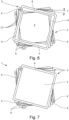
- Fig. 6 shows an example of three holding frames 3 arranged one above the other, which are arranged twisted relative to one another about their central axis M.
- the angle of rotation ⁇ between the first holding frame 3 and the second holding frame arranged underneath is 7.5°.
- Fig. 7 shows the same arrangement of three holding frames 3, the individual holding frames 3 each holding two electrodes 2, which together form a spark gap.
- the electrode 2 arranged between the first holding frame 3 and the second holding frame 3 ' is visible through the receiving opening 6 in the first, upper holding frame 3, so that a control element 7 inserted into the receiving opening 6 can contact this electrode 2 on its front side.
- a locking element 12 is formed on the sides of the holding frame 3, which interacts with the corresponding locking element 12 of a second holding frame 3 when the two holding frames 3 are stacked one on top of the other.
- the assembly of a surge protection device with such a spark gap arrangement 1 is also very simple, since the individual components can be stacked one after the other. The assembly can be carried out in particular from one direction.
- a housing half-shell 15 is shown, which forms part of a housing accommodating the spark gap arrangement 1.
- the dimensions of the housing half-shell 15 are only slightly larger than the external dimensions of the spark gap arrangement 1 or the individual holding frames 3, since no additional installation space is required for the control elements 7.
- the contacting of individual electrodes 2 by control elements 7 is shown in the sectional view 8 and 9 can be seen, in which in the two sectional views only the electrodes 2 are shown in their mutually twisted position predetermined by the holding frames 3, but not the holding frames 3 themselves.
- the first electrode 21 arranged on the far right is contacted on one side by the contact plate 14, which in turn is connected to a connection element 16 for the electrical connection of a neutral conductor.
- On the other side of the first electrode 21 is located the second electrode 22, which are spaced apart from one another by the support section of the first holding frame arranged between the two electrodes 21, 22, so that the two electrodes 21, 22 form a first spark gap.
- the second electrode 22 and the third electrode 23 arranged at a distance therefrom form a second spark gap and the third electrode 23 and the fourth electrode 24 which are also arranged at a distance therefrom form a third spark gap of the spark gap arrangement 1.
- the side facing away from the third electrode 23 Fourth electrode 24 is then connected to the contact plate 23, not shown here, which is intended for connecting a PE conductor.
- a busbar 17 is arranged and electrically connected to the contact plate 14, with the two ends 18, 19 of the busbar 16 each contacting a first connection of a control element 7, 7 '.
- the first control element 7 shown above is arranged in a first opening 6 in the first holding frame 3. As a result, it can use its second connection to contact the second electrode 22, which is arranged twisted relative to the first electrode 21 in the first holding frame 3, on its front side, without touching the first electrode 21 with its second connection.
- the second control element 7' shown is arranged in a second opening 6 in the first holding frame 3.
- This control element 7' can thereby use its second connection to contact the third electrode 23, which is arranged in the second holding frame 3', on its front side, without contacting the first electrode 21 and the second electrode 22 with its second connection.
- the two control elements 7, 7' are each arranged in an opening 6 in the first holding frame 3, the required insulation distances between the control elements 7, 7' themselves and between the control elements 7, 7' and the electrodes not contacted by them can also be achieved 21, 22 must be adhered to.
Landscapes
- Electrostatic Separation (AREA)
- Packaging Of Annular Or Rod-Shaped Articles, Wearing Apparel, Cassettes, Or The Like (AREA)
Priority Applications (1)
| Application Number | Priority Date | Filing Date | Title |
|---|---|---|---|
| SI202330024T SI4270689T1 (sl) | 2022-04-28 | 2023-04-20 | Razporeditev iskrišča |
Applications Claiming Priority (1)
| Application Number | Priority Date | Filing Date | Title |
|---|---|---|---|
| DE102022110329.3A DE102022110329A1 (de) | 2022-04-28 | 2022-04-28 | Funkenstreckenanordnung |
Publications (2)
| Publication Number | Publication Date |
|---|---|
| EP4270689A1 true EP4270689A1 (fr) | 2023-11-01 |
| EP4270689B1 EP4270689B1 (fr) | 2025-03-26 |
Family
ID=88150272
Family Applications (1)
| Application Number | Title | Priority Date | Filing Date |
|---|---|---|---|
| EP23168906.8A Active EP4270689B1 (fr) | 2022-04-28 | 2023-04-20 | Dispositif éclateur |
Country Status (5)
| Country | Link |
|---|---|
| US (1) | US12244123B2 (fr) |
| EP (1) | EP4270689B1 (fr) |
| CN (1) | CN116979374A (fr) |
| DE (1) | DE102022110329A1 (fr) |
| SI (1) | SI4270689T1 (fr) |
Citations (6)
| Publication number | Priority date | Publication date | Assignee | Title |
|---|---|---|---|---|
| CH403040A (de) * | 1961-03-23 | 1965-11-30 | Licentia Gmbh | Löschfunkenstrecke für Überspannungsableiter in einem Gehäuse aus lichtbogenbeständigem Material |
| DE102011102864A1 (de) | 2010-10-22 | 2012-04-26 | Dehn + Söhne GmbH | Funkenstrecke mit mehreren in Reihe geschalteten, in Stapelanordnung befindlichen Einzelfunkenstrecken |
| DE202013102647U1 (de) | 2013-06-19 | 2013-06-26 | Obo Bettermann Gmbh & Co. Kg | Mehrfachfunkenstrecke |
| DE102016114787A1 (de) | 2015-11-09 | 2017-05-11 | DEHN + SÖHNE GmbH + Co. KG. | Trägereinheit für in Reihe schalt- und stapelbare Funkenstrecken |
| DE102018118898B3 (de) | 2018-08-03 | 2019-10-24 | Phoenix Contact Gmbh & Co. Kg | Halteanordnung und Anordnung von mindestens zwei Stapelfunkenstrecken |
| DE102018132088B3 (de) * | 2018-12-13 | 2020-06-18 | Phoenix Contact Gmbh & Co. Kg | Halteelement zum Halten einer Elektrode einer Funkenstrecke, Anordnung sowie Funkenstrecke mit wenigstens einem Halteelement |
-
2022
- 2022-04-28 DE DE102022110329.3A patent/DE102022110329A1/de active Pending
-
2023
- 2023-04-20 SI SI202330024T patent/SI4270689T1/sl unknown
- 2023-04-20 EP EP23168906.8A patent/EP4270689B1/fr active Active
- 2023-04-26 US US18/307,140 patent/US12244123B2/en active Active
- 2023-04-28 CN CN202310485701.8A patent/CN116979374A/zh active Pending
Patent Citations (6)
| Publication number | Priority date | Publication date | Assignee | Title |
|---|---|---|---|---|
| CH403040A (de) * | 1961-03-23 | 1965-11-30 | Licentia Gmbh | Löschfunkenstrecke für Überspannungsableiter in einem Gehäuse aus lichtbogenbeständigem Material |
| DE102011102864A1 (de) | 2010-10-22 | 2012-04-26 | Dehn + Söhne GmbH | Funkenstrecke mit mehreren in Reihe geschalteten, in Stapelanordnung befindlichen Einzelfunkenstrecken |
| DE202013102647U1 (de) | 2013-06-19 | 2013-06-26 | Obo Bettermann Gmbh & Co. Kg | Mehrfachfunkenstrecke |
| DE102016114787A1 (de) | 2015-11-09 | 2017-05-11 | DEHN + SÖHNE GmbH + Co. KG. | Trägereinheit für in Reihe schalt- und stapelbare Funkenstrecken |
| DE102018118898B3 (de) | 2018-08-03 | 2019-10-24 | Phoenix Contact Gmbh & Co. Kg | Halteanordnung und Anordnung von mindestens zwei Stapelfunkenstrecken |
| DE102018132088B3 (de) * | 2018-12-13 | 2020-06-18 | Phoenix Contact Gmbh & Co. Kg | Halteelement zum Halten einer Elektrode einer Funkenstrecke, Anordnung sowie Funkenstrecke mit wenigstens einem Halteelement |
Also Published As
| Publication number | Publication date |
|---|---|
| EP4270689B1 (fr) | 2025-03-26 |
| CN116979374A (zh) | 2023-10-31 |
| DE102022110329A1 (de) | 2023-11-02 |
| US20230352914A1 (en) | 2023-11-02 |
| US12244123B2 (en) | 2025-03-04 |
| SI4270689T1 (sl) | 2025-06-30 |
Similar Documents
| Publication | Publication Date | Title |
|---|---|---|
| EP0595234B2 (fr) | Connecteur de câble pour câbles multibrins | |
| DE102018118906B3 (de) | Überspannungsschutzgerät | |
| DE102018118898B3 (de) | Halteanordnung und Anordnung von mindestens zwei Stapelfunkenstrecken | |
| DE102016225598A1 (de) | Energiespeichervorrichtung | |
| DE102018118904B3 (de) | Anordnung von Stapelfunkenstrecken und Vorrichtung zum Zusammenhalten und Kontaktieren von Stapelfunkenstrecken | |
| AT390528B (de) | Funkenstrecke fuer die begrenzung von ueberspannungen | |
| DE3150568C1 (de) | Kabelanschlußelement | |
| EP2882050A2 (fr) | Éclateur multiple pour la protection anti-foudre | |
| EP0083738A2 (fr) | Elément de connexion pour câbles électriques pourvu de bornes tranchantes | |
| EP2738778B1 (fr) | Agencement de protection contre les surtensions doté de varistances en forme de disque | |
| EP4270689B1 (fr) | Dispositif éclateur | |
| EP0037363B1 (fr) | Dispositif de protection contre les surtensions | |
| WO2019007566A1 (fr) | Limiteur pour la protection contre les surtensions | |
| EP1535371B1 (fr) | Borne de traversee | |
| DE2633187A1 (de) | Gehaeuse zur aufnahme von elektrotechnischen oder elektronischen geraeten mit einer vielfach-kabelabdichtung und- kabelzugentlastung | |
| EP3507873B1 (fr) | Éclateur à gaz | |
| DE102023128297A1 (de) | Funkenstreckenanordnung | |
| DE202016001937U1 (de) | Überspannungsschutzanordnung mit mehreren, auf einer ersten Seite einer n-eckigen Trägerplatte angeordneten, scheibenförmigen Varistoren | |
| DE102012202240A1 (de) | Klemmkörper für eine Anschlussklemme | |
| WO2016206932A1 (fr) | Module d'un dispositif à bornes permettant de connecter des conducteurs électriques | |
| BE1032147B1 (de) | Sensor-Aktor-Verteiler | |
| DE102019213175A1 (de) | Verbindungsanordnung | |
| EP3270474B1 (fr) | Éclateur | |
| EP4270688A1 (fr) | Éclateur multiple | |
| EP3507849A1 (fr) | Batterie comprenant un ensemble d'éléments comprimés |
Legal Events
| Date | Code | Title | Description |
|---|---|---|---|
| PUAI | Public reference made under article 153(3) epc to a published international application that has entered the european phase |
Free format text: ORIGINAL CODE: 0009012 |
|
| STAA | Information on the status of an ep patent application or granted ep patent |
Free format text: STATUS: THE APPLICATION HAS BEEN PUBLISHED |
|
| AK | Designated contracting states |
Kind code of ref document: A1 Designated state(s): AL AT BE BG CH CY CZ DE DK EE ES FI FR GB GR HR HU IE IS IT LI LT LU LV MC ME MK MT NL NO PL PT RO RS SE SI SK SM TR |
|
| STAA | Information on the status of an ep patent application or granted ep patent |
Free format text: STATUS: REQUEST FOR EXAMINATION WAS MADE |
|
| 17P | Request for examination filed |
Effective date: 20240430 |
|
| RBV | Designated contracting states (corrected) |
Designated state(s): AL AT BE BG CH CY CZ DE DK EE ES FI FR GB GR HR HU IE IS IT LI LT LU LV MC ME MK MT NL NO PL PT RO RS SE SI SK SM TR |
|
| GRAP | Despatch of communication of intention to grant a patent |
Free format text: ORIGINAL CODE: EPIDOSNIGR1 |
|
| STAA | Information on the status of an ep patent application or granted ep patent |
Free format text: STATUS: GRANT OF PATENT IS INTENDED |
|
| INTG | Intention to grant announced |
Effective date: 20241016 |
|
| P01 | Opt-out of the competence of the unified patent court (upc) registered |
Free format text: CASE NUMBER: APP_65616/2024 Effective date: 20241212 |
|
| GRAS | Grant fee paid |
Free format text: ORIGINAL CODE: EPIDOSNIGR3 |
|
| GRAA | (expected) grant |
Free format text: ORIGINAL CODE: 0009210 |
|
| STAA | Information on the status of an ep patent application or granted ep patent |
Free format text: STATUS: THE PATENT HAS BEEN GRANTED |
|
| AK | Designated contracting states |
Kind code of ref document: B1 Designated state(s): AL AT BE BG CH CY CZ DE DK EE ES FI FR GB GR HR HU IE IS IT LI LT LU LV MC ME MK MT NL NO PL PT RO RS SE SI SK SM TR |
|
| REG | Reference to a national code |
Ref country code: GB Ref legal event code: FG4D Free format text: NOT ENGLISH |
|
| REG | Reference to a national code |
Ref country code: CH Ref legal event code: EP |
|
| REG | Reference to a national code |
Ref country code: DE Ref legal event code: R096 Ref document number: 502023000719 Country of ref document: DE |
|
| REG | Reference to a national code |
Ref country code: IE Ref legal event code: FG4D Free format text: LANGUAGE OF EP DOCUMENT: GERMAN |
|
| PG25 | Lapsed in a contracting state [announced via postgrant information from national office to epo] |
Ref country code: RS Free format text: LAPSE BECAUSE OF FAILURE TO SUBMIT A TRANSLATION OF THE DESCRIPTION OR TO PAY THE FEE WITHIN THE PRESCRIBED TIME-LIMIT Effective date: 20250626 |
|
| PG25 | Lapsed in a contracting state [announced via postgrant information from national office to epo] |
Ref country code: FI Free format text: LAPSE BECAUSE OF FAILURE TO SUBMIT A TRANSLATION OF THE DESCRIPTION OR TO PAY THE FEE WITHIN THE PRESCRIBED TIME-LIMIT Effective date: 20250326 |
|
| PGFP | Annual fee paid to national office [announced via postgrant information from national office to epo] |
Ref country code: DE Payment date: 20250626 Year of fee payment: 3 |
|
| REG | Reference to a national code |
Ref country code: LT Ref legal event code: MG9D |
|
| PG25 | Lapsed in a contracting state [announced via postgrant information from national office to epo] |
Ref country code: NO Free format text: LAPSE BECAUSE OF FAILURE TO SUBMIT A TRANSLATION OF THE DESCRIPTION OR TO PAY THE FEE WITHIN THE PRESCRIBED TIME-LIMIT Effective date: 20250626 |
|
| PG25 | Lapsed in a contracting state [announced via postgrant information from national office to epo] |
Ref country code: HR Free format text: LAPSE BECAUSE OF FAILURE TO SUBMIT A TRANSLATION OF THE DESCRIPTION OR TO PAY THE FEE WITHIN THE PRESCRIBED TIME-LIMIT Effective date: 20250326 |
|
| PG25 | Lapsed in a contracting state [announced via postgrant information from national office to epo] |
Ref country code: LV Free format text: LAPSE BECAUSE OF FAILURE TO SUBMIT A TRANSLATION OF THE DESCRIPTION OR TO PAY THE FEE WITHIN THE PRESCRIBED TIME-LIMIT Effective date: 20250326 |
|
| PGFP | Annual fee paid to national office [announced via postgrant information from national office to epo] |
Ref country code: FR Payment date: 20250424 Year of fee payment: 3 |
|
| PG25 | Lapsed in a contracting state [announced via postgrant information from national office to epo] |
Ref country code: GR Free format text: LAPSE BECAUSE OF FAILURE TO SUBMIT A TRANSLATION OF THE DESCRIPTION OR TO PAY THE FEE WITHIN THE PRESCRIBED TIME-LIMIT Effective date: 20250627 Ref country code: BG Free format text: LAPSE BECAUSE OF FAILURE TO SUBMIT A TRANSLATION OF THE DESCRIPTION OR TO PAY THE FEE WITHIN THE PRESCRIBED TIME-LIMIT Effective date: 20250326 |
|
| PGFP | Annual fee paid to national office [announced via postgrant information from national office to epo] |
Ref country code: AT Payment date: 20250721 Year of fee payment: 3 |
|
| PGFP | Annual fee paid to national office [announced via postgrant information from national office to epo] |
Ref country code: SI Payment date: 20250505 Year of fee payment: 3 |
|
| REG | Reference to a national code |
Ref country code: NL Ref legal event code: MP Effective date: 20250326 |
|
| PG25 | Lapsed in a contracting state [announced via postgrant information from national office to epo] |
Ref country code: NL Free format text: LAPSE BECAUSE OF FAILURE TO SUBMIT A TRANSLATION OF THE DESCRIPTION OR TO PAY THE FEE WITHIN THE PRESCRIBED TIME-LIMIT Effective date: 20250326 |
|
| PG25 | Lapsed in a contracting state [announced via postgrant information from national office to epo] |
Ref country code: SE Free format text: LAPSE BECAUSE OF FAILURE TO SUBMIT A TRANSLATION OF THE DESCRIPTION OR TO PAY THE FEE WITHIN THE PRESCRIBED TIME-LIMIT Effective date: 20250326 |
|
| PG25 | Lapsed in a contracting state [announced via postgrant information from national office to epo] |
Ref country code: SM Free format text: LAPSE BECAUSE OF FAILURE TO SUBMIT A TRANSLATION OF THE DESCRIPTION OR TO PAY THE FEE WITHIN THE PRESCRIBED TIME-LIMIT Effective date: 20250326 |
|
| PG25 | Lapsed in a contracting state [announced via postgrant information from national office to epo] |
Ref country code: ES Free format text: LAPSE BECAUSE OF FAILURE TO SUBMIT A TRANSLATION OF THE DESCRIPTION OR TO PAY THE FEE WITHIN THE PRESCRIBED TIME-LIMIT Effective date: 20250326 Ref country code: PT Free format text: LAPSE BECAUSE OF FAILURE TO SUBMIT A TRANSLATION OF THE DESCRIPTION OR TO PAY THE FEE WITHIN THE PRESCRIBED TIME-LIMIT Effective date: 20250728 |
|
| PG25 | Lapsed in a contracting state [announced via postgrant information from national office to epo] |
Ref country code: IT Free format text: LAPSE BECAUSE OF FAILURE TO SUBMIT A TRANSLATION OF THE DESCRIPTION OR TO PAY THE FEE WITHIN THE PRESCRIBED TIME-LIMIT Effective date: 20250326 Ref country code: PL Free format text: LAPSE BECAUSE OF FAILURE TO SUBMIT A TRANSLATION OF THE DESCRIPTION OR TO PAY THE FEE WITHIN THE PRESCRIBED TIME-LIMIT Effective date: 20250326 |
|
| PG25 | Lapsed in a contracting state [announced via postgrant information from national office to epo] |
Ref country code: EE Free format text: LAPSE BECAUSE OF FAILURE TO SUBMIT A TRANSLATION OF THE DESCRIPTION OR TO PAY THE FEE WITHIN THE PRESCRIBED TIME-LIMIT Effective date: 20250326 |
|
| PG25 | Lapsed in a contracting state [announced via postgrant information from national office to epo] |
Ref country code: RO Free format text: LAPSE BECAUSE OF FAILURE TO SUBMIT A TRANSLATION OF THE DESCRIPTION OR TO PAY THE FEE WITHIN THE PRESCRIBED TIME-LIMIT Effective date: 20250326 |
|
| PG25 | Lapsed in a contracting state [announced via postgrant information from national office to epo] |
Ref country code: SK Free format text: LAPSE BECAUSE OF FAILURE TO SUBMIT A TRANSLATION OF THE DESCRIPTION OR TO PAY THE FEE WITHIN THE PRESCRIBED TIME-LIMIT Effective date: 20250326 |
|
| PG25 | Lapsed in a contracting state [announced via postgrant information from national office to epo] |
Ref country code: IS Free format text: LAPSE BECAUSE OF FAILURE TO SUBMIT A TRANSLATION OF THE DESCRIPTION OR TO PAY THE FEE WITHIN THE PRESCRIBED TIME-LIMIT Effective date: 20250726 |
|
| PG25 | Lapsed in a contracting state [announced via postgrant information from national office to epo] |
Ref country code: LU Free format text: LAPSE BECAUSE OF NON-PAYMENT OF DUE FEES Effective date: 20250420 |
|
| PG25 | Lapsed in a contracting state [announced via postgrant information from national office to epo] |
Ref country code: MC Free format text: LAPSE BECAUSE OF FAILURE TO SUBMIT A TRANSLATION OF THE DESCRIPTION OR TO PAY THE FEE WITHIN THE PRESCRIBED TIME-LIMIT Effective date: 20250326 |
|
| REG | Reference to a national code |
Ref country code: BE Ref legal event code: MM Effective date: 20250430 |
|
| REG | Reference to a national code |
Ref country code: DE Ref legal event code: R097 Ref document number: 502023000719 Country of ref document: DE |
|
| PG25 | Lapsed in a contracting state [announced via postgrant information from national office to epo] |
Ref country code: DK Free format text: LAPSE BECAUSE OF FAILURE TO SUBMIT A TRANSLATION OF THE DESCRIPTION OR TO PAY THE FEE WITHIN THE PRESCRIBED TIME-LIMIT Effective date: 20250326 |
|
| PG25 | Lapsed in a contracting state [announced via postgrant information from national office to epo] |
Ref country code: BE Free format text: LAPSE BECAUSE OF NON-PAYMENT OF DUE FEES Effective date: 20250430 |
|
| PG25 | Lapsed in a contracting state [announced via postgrant information from national office to epo] |
Ref country code: CZ Free format text: LAPSE BECAUSE OF FAILURE TO SUBMIT A TRANSLATION OF THE DESCRIPTION OR TO PAY THE FEE WITHIN THE PRESCRIBED TIME-LIMIT Effective date: 20250326 |
|
| PLBE | No opposition filed within time limit |
Free format text: ORIGINAL CODE: 0009261 |
|
| STAA | Information on the status of an ep patent application or granted ep patent |
Free format text: STATUS: NO OPPOSITION FILED WITHIN TIME LIMIT |
|
| REG | Reference to a national code |
Ref country code: CH Ref legal event code: L10 Free format text: ST27 STATUS EVENT CODE: U-0-0-L10-L00 (AS PROVIDED BY THE NATIONAL OFFICE) Effective date: 20260211 |
|
| 26N | No opposition filed |
Effective date: 20260105 |
|
| PG25 | Lapsed in a contracting state [announced via postgrant information from national office to epo] |
Ref country code: IE Free format text: LAPSE BECAUSE OF NON-PAYMENT OF DUE FEES Effective date: 20250420 |