EP4279869B1 - Détermination d'un état d'un véhicule sur une route - Google Patents
Détermination d'un état d'un véhicule sur une route Download PDFInfo
- Publication number
- EP4279869B1 EP4279869B1 EP22173553.3A EP22173553A EP4279869B1 EP 4279869 B1 EP4279869 B1 EP 4279869B1 EP 22173553 A EP22173553 A EP 22173553A EP 4279869 B1 EP4279869 B1 EP 4279869B1
- Authority
- EP
- European Patent Office
- Prior art keywords
- vehicle
- initialized
- filter
- data
- sensor data
- Prior art date
- Legal status (The legal status is an assumption and is not a legal conclusion. Google has not performed a legal analysis and makes no representation as to the accuracy of the status listed.)
- Active
Links
Images


Classifications
-
- G—PHYSICS
- G01—MEASURING; TESTING
- G01C—MEASURING DISTANCES, LEVELS OR BEARINGS; SURVEYING; NAVIGATION; GYROSCOPIC INSTRUMENTS; PHOTOGRAMMETRY OR VIDEOGRAMMETRY
- G01C21/00—Navigation; Navigational instruments not provided for in groups G01C1/00 - G01C19/00
- G01C21/26—Navigation; Navigational instruments not provided for in groups G01C1/00 - G01C19/00 specially adapted for navigation in a road network
- G01C21/28—Navigation; Navigational instruments not provided for in groups G01C1/00 - G01C19/00 specially adapted for navigation in a road network with correlation of data from several navigational instruments
-
- B—PERFORMING OPERATIONS; TRANSPORTING
- B60—VEHICLES IN GENERAL
- B60W—CONJOINT CONTROL OF VEHICLE SUB-UNITS OF DIFFERENT TYPE OR DIFFERENT FUNCTION; CONTROL SYSTEMS SPECIALLY ADAPTED FOR HYBRID VEHICLES; ROAD VEHICLE DRIVE CONTROL SYSTEMS FOR PURPOSES NOT RELATED TO THE CONTROL OF A PARTICULAR SUB-UNIT
- B60W50/00—Details of control systems for road vehicle drive control not related to the control of a particular sub-unit, e.g. process diagnostic or vehicle driver interfaces
-
- B—PERFORMING OPERATIONS; TRANSPORTING
- B60—VEHICLES IN GENERAL
- B60W—CONJOINT CONTROL OF VEHICLE SUB-UNITS OF DIFFERENT TYPE OR DIFFERENT FUNCTION; CONTROL SYSTEMS SPECIALLY ADAPTED FOR HYBRID VEHICLES; ROAD VEHICLE DRIVE CONTROL SYSTEMS FOR PURPOSES NOT RELATED TO THE CONTROL OF A PARTICULAR SUB-UNIT
- B60W60/00—Drive control systems specially adapted for autonomous road vehicles
- B60W60/001—Planning or execution of driving tasks
-
- G—PHYSICS
- G01—MEASURING; TESTING
- G01C—MEASURING DISTANCES, LEVELS OR BEARINGS; SURVEYING; NAVIGATION; GYROSCOPIC INSTRUMENTS; PHOTOGRAMMETRY OR VIDEOGRAMMETRY
- G01C21/00—Navigation; Navigational instruments not provided for in groups G01C1/00 - G01C19/00
- G01C21/10—Navigation; Navigational instruments not provided for in groups G01C1/00 - G01C19/00 by using measurements of speed or acceleration
- G01C21/12—Navigation; Navigational instruments not provided for in groups G01C1/00 - G01C19/00 by using measurements of speed or acceleration executed aboard the object being navigated; Dead reckoning
- G01C21/16—Navigation; Navigational instruments not provided for in groups G01C1/00 - G01C19/00 by using measurements of speed or acceleration executed aboard the object being navigated; Dead reckoning by integrating acceleration or speed, i.e. inertial navigation
- G01C21/165—Navigation; Navigational instruments not provided for in groups G01C1/00 - G01C19/00 by using measurements of speed or acceleration executed aboard the object being navigated; Dead reckoning by integrating acceleration or speed, i.e. inertial navigation combined with non-inertial navigation instruments
- G01C21/1656—Navigation; Navigational instruments not provided for in groups G01C1/00 - G01C19/00 by using measurements of speed or acceleration executed aboard the object being navigated; Dead reckoning by integrating acceleration or speed, i.e. inertial navigation combined with non-inertial navigation instruments with passive imaging devices, e.g. cameras
-
- G—PHYSICS
- G01—MEASURING; TESTING
- G01C—MEASURING DISTANCES, LEVELS OR BEARINGS; SURVEYING; NAVIGATION; GYROSCOPIC INSTRUMENTS; PHOTOGRAMMETRY OR VIDEOGRAMMETRY
- G01C21/00—Navigation; Navigational instruments not provided for in groups G01C1/00 - G01C19/00
- G01C21/26—Navigation; Navigational instruments not provided for in groups G01C1/00 - G01C19/00 specially adapted for navigation in a road network
- G01C21/28—Navigation; Navigational instruments not provided for in groups G01C1/00 - G01C19/00 specially adapted for navigation in a road network with correlation of data from several navigational instruments
- G01C21/30—Map- or contour-matching
-
- G—PHYSICS
- G01—MEASURING; TESTING
- G01C—MEASURING DISTANCES, LEVELS OR BEARINGS; SURVEYING; NAVIGATION; GYROSCOPIC INSTRUMENTS; PHOTOGRAMMETRY OR VIDEOGRAMMETRY
- G01C21/00—Navigation; Navigational instruments not provided for in groups G01C1/00 - G01C19/00
- G01C21/26—Navigation; Navigational instruments not provided for in groups G01C1/00 - G01C19/00 specially adapted for navigation in a road network
- G01C21/34—Route searching; Route guidance
- G01C21/3446—Details of route searching algorithms, e.g. Dijkstra, A*, arc-flags or using precalculated routes
-
- G—PHYSICS
- G01—MEASURING; TESTING
- G01S—RADIO DIRECTION-FINDING; RADIO NAVIGATION; DETERMINING DISTANCE OR VELOCITY BY USE OF RADIO WAVES; LOCATING OR PRESENCE-DETECTING BY USE OF THE REFLECTION OR RERADIATION OF RADIO WAVES; ANALOGOUS ARRANGEMENTS USING OTHER WAVES
- G01S19/00—Satellite radio beacon positioning systems; Determining position, velocity or attitude using signals transmitted by such systems
- G01S19/38—Determining a navigation solution using signals transmitted by a satellite radio beacon positioning system
- G01S19/39—Determining a navigation solution using signals transmitted by a satellite radio beacon positioning system the satellite radio beacon positioning system transmitting time-stamped messages, e.g. GPS [Global Positioning System], GLONASS [Global Orbiting Navigation Satellite System] or GALILEO
- G01S19/42—Determining position
- G01S19/45—Determining position by combining measurements of signals from the satellite radio beacon positioning system with a supplementary measurement
- G01S19/47—Determining position by combining measurements of signals from the satellite radio beacon positioning system with a supplementary measurement the supplementary measurement being an inertial measurement, e.g. tightly coupled inertial
-
- G—PHYSICS
- G06—COMPUTING OR CALCULATING; COUNTING
- G06N—COMPUTING ARRANGEMENTS BASED ON SPECIFIC COMPUTATIONAL MODELS
- G06N20/00—Machine learning
-
- G—PHYSICS
- G06—COMPUTING OR CALCULATING; COUNTING
- G06V—IMAGE OR VIDEO RECOGNITION OR UNDERSTANDING
- G06V20/00—Scenes; Scene-specific elements
- G06V20/50—Context or environment of the image
- G06V20/56—Context or environment of the image exterior to a vehicle by using sensors mounted on the vehicle
- G06V20/588—Recognition of the road, e.g. of lane markings; Recognition of the vehicle driving pattern in relation to the road
-
- B—PERFORMING OPERATIONS; TRANSPORTING
- B60—VEHICLES IN GENERAL
- B60W—CONJOINT CONTROL OF VEHICLE SUB-UNITS OF DIFFERENT TYPE OR DIFFERENT FUNCTION; CONTROL SYSTEMS SPECIALLY ADAPTED FOR HYBRID VEHICLES; ROAD VEHICLE DRIVE CONTROL SYSTEMS FOR PURPOSES NOT RELATED TO THE CONTROL OF A PARTICULAR SUB-UNIT
- B60W50/00—Details of control systems for road vehicle drive control not related to the control of a particular sub-unit, e.g. process diagnostic or vehicle driver interfaces
- B60W2050/0001—Details of the control system
- B60W2050/0043—Signal treatments, identification of variables or parameters, parameter estimation or state estimation
- B60W2050/0052—Filtering, filters
-
- B—PERFORMING OPERATIONS; TRANSPORTING
- B60—VEHICLES IN GENERAL
- B60W—CONJOINT CONTROL OF VEHICLE SUB-UNITS OF DIFFERENT TYPE OR DIFFERENT FUNCTION; CONTROL SYSTEMS SPECIALLY ADAPTED FOR HYBRID VEHICLES; ROAD VEHICLE DRIVE CONTROL SYSTEMS FOR PURPOSES NOT RELATED TO THE CONTROL OF A PARTICULAR SUB-UNIT
- B60W2420/00—Indexing codes relating to the type of sensors based on the principle of their operation
-
- B—PERFORMING OPERATIONS; TRANSPORTING
- B60—VEHICLES IN GENERAL
- B60W—CONJOINT CONTROL OF VEHICLE SUB-UNITS OF DIFFERENT TYPE OR DIFFERENT FUNCTION; CONTROL SYSTEMS SPECIALLY ADAPTED FOR HYBRID VEHICLES; ROAD VEHICLE DRIVE CONTROL SYSTEMS FOR PURPOSES NOT RELATED TO THE CONTROL OF A PARTICULAR SUB-UNIT
- B60W2530/00—Input parameters relating to vehicle conditions or values, not covered by groups B60W2510/00 or B60W2520/00
Definitions
- the present disclosure relates to methods and systems for determining a state of a vehicle on a road. More specifically, embodiments and aspects of the present disclosure relate to initialization of filters for the vehicle on a road and systems and methods for selection of the initialized filters by means of machine learning algorithms to determine the state of the vehicle on the road.
- ADAS driver-assistance systems
- ACC adaptive cruise control
- forward collision warning etc.
- AD Autonomous Driving
- ADAS and AD will herein be referred to under the common term Automated Driving System (ADS) corresponding to all of the different levels of automation as for example defined by the SAE J3016 levels (0 - 5) of driving automation, and in particular for level 4 and 5.
- ADS Automated Driving System
- An ADS may be construed as a complex combination of various components that can be defined as systems where perception, decision making, and operation of the vehicle are performed by electronics and machinery instead of a human driver, and as introduction of automation into road traffic. This includes handling of the vehicle, destination, as well as awareness of surroundings. While the automated system has control over the vehicle, it allows the human operator to leave all or at least some responsibilities to the system.
- An ADS commonly combines a variety of sensors to perceive the vehicle's surroundings, such as e.g. radar, LIDAR, sonar, camera, navigation system e.g. GPS, odometer and/or inertial measurement units (IMUs), upon which advanced control systems may interpret sensory information to identify appropriate navigation paths, as well as obstacles, free-space areas, and/or relevant signage.
- GNSS Global Navigation Satellite Systems
- GPS Global Positioning System
- GLONASS Globalnaya Navigazionnaya Sputnikovaya Sistema
- Galileo Beidou
- ADS Automated Driving System
- a method for determining a state of a vehicle on a road portion having two or more lanes comprising an Automated Driving System (ADS) feature.
- the method comprises obtaining map data associated with the road portion and obtaining positioning data indicating a pose of the vehicle on the road and obtaining sensor data from a sensor system of the vehicle. Further the method comprises initializing a plurality of filters for the road portion wherein one filter is initialized per lane of the road portion based on the obtained map data, the obtained positioning data, and the obtained sensor data, wherein each filter indicates an estimated state of the vehicle on the road portion.
- ADS Automated Driving System
- the method comprises associating one or more sensor data point(s) in the obtained sensor data to a corresponding map-element of the obtained map data and determining one or more normalized similarity score(s) between the associated obtained map data and the obtained sensor data. Further, the method comprises determining one or more multivariate time-series data based on the determined one or more normalized similarity score(s), wherein each multivariate time-series data is attributed to a corresponding initialized filter among the plurality of initialized filters. In addition, the method comprises providing the one or more multivariate time-series data as input to a trained machine-learning algorithm.
- the trained machine learning algorithm is configured for determining a confidence probability value for each initialized filter of the plurality of initialized filters by means of a probabilistic classifier. Further the machine learning algorithm is configured for selecting one of the initialized filters, by comparing the confidence probability values determined for each initialized filter in conjunction with one or more multi-objective optimized coefficient(s), each optimized coefficient being indicative of an optimization, e.g. an optimized trade-off, between a readiness performance indicator and an accuracy performance indicator for selecting a single initialized filter as an output of the machine learning algorithm. The output of the machine learning algorithm is indicative of a current state of the vehicle on the road portion. The method further comprises controlling the ADS feature of the vehicle based on the selected initialized filter.
- the presented method by employing a data-driven approach comprising the use of machine learning algorithms to identify and select the most promising initialized filter out of the plurality of initialized filters per lane of a multi-lane road, the possibilities of accurately and efficiently estimating the state of the vehicle on the road portion are noticeably improved.
- This advantage is particularly noteworthy in comparison with rule-based algorithm designs for identifying the most accurate initialized filter indicative of the state of the vehicle on the road portion.
- the rule-based approaches may be capable of accurately determining the state of the vehicle on the road portion, the likelihood of avoiding unforeseeable corner cases is considerably enhanced by training and employing the machine learning algorithm according to the present invention.
- the trained machine learning algorithm is used to influence and promote behavior that leads to an increased possibility of generating interesting scenarios, including the corner case scenarios involving multiple environmental variables or conditions happening simultaneously or outside the conventional levels.
- the versatility of the proposed solution establishes the proposed method, and corresponding system and vehicle to be readily adaptable for varying traffic situations or road and transportation infrastructure in different countries.
- each initialized filter may be one of a Bayesian filter and a combination of multiple Bayesian filters.
- each Bayesian filter may be one of Kalman Filter, Extended Kalman Filter, EKF, Unscented Kalman Filter, UKF, Cubature Kalman Filter, CKF, and Particle Filter, PF.
- the obtained sensor data may comprise information about a state of one or more other vehicles in the surrounding environment of the vehicle, lane marker geometry, lane marker type, traffic sign information, road barrier information, and Inertial Measurement Unit, IMU, data.
- the map data may comprise HD-map data.
- the method may further comprise determining one or more normalized similarity score(s) between the associated obtained map data and the obtained sensor data by computing an association cost value for each sensor data point of the one or more sensor data point(s) associated to a corresponding map element; and selecting a sensor data point and map-element combination having the smallest association cost value.
- the method may further comprise determining the one or more multivariate time-series data based on the determined one or more normalized similarity score(s) by obtaining one or more time-dependent feature(s) of each determined normalized similarity score.
- the trained machine learning algorithm may be further configured for sorting the determined confidence probability values for the plurality of the initialized filters based on the confidence level of each determined confidence probability value.
- the readiness performance indicator may comprise any one of an availability performance indicator comprising a proportion of the one or more multivariate time-series data for which a selection of a single initialized filter is performed by the trained machine learning algorithm.
- the readiness performance indicator may further comprise an earliness performance indicator comprising an average fraction passed of the one or more multivariate time-series data before a selection of a single initialized filter is performed by the trained machine learning algorithm.
- the performance accuracy indicator may comprise a proportion of correctly-selected single initialized filters by the trained machine learning algorithm, being indicative of the current state of the vehicle on the road portion.
- a (non-transitory) computer-readable storage medium storing one or more programs configured to be executed by one or more processors of a processing system, the one or more programs comprising instructions for performing the method according to any one of the embodiments of the method disclosed herein.
- non-transitory is intended to describe a computer-readable storage medium (or “memory”) excluding propagating electromagnetic signals, but are not intended to otherwise limit the type of physical computer-readable storage device that is encompassed by the phrase computer-readable medium or memory.
- the terms “non-transitory computer readable medium” or “tangible memory” are intended to encompass types of storage devices that do not necessarily store information permanently, including for example, random access memory (RAM).
- Program instructions and data stored on a tangible computer-accessible storage medium in non-transitory form may further be transmitted by transmission media or signals such as electrical, electromagnetic, or digital signals, which may be conveyed via a communication medium such as a network and/or a wireless link.
- the term “non-transitory”, as used herein is a limitation of the medium itself (i.e., tangible, not a signal) as opposed to a limitation on data storage persistency (e.g., RAM vs. ROM).
- a computer program product comprising instructions which, when the program is executed by one or more processors of a processing system, causes the processing system to carry out the method according to any one of the embodiments of the method disclosed herein.
- a system for determining a state of a vehicle on a road portion having two or more lanes comprising an Automated Driving System, ADS, feature
- the system comprising processing circuitry configured to obtain map data associated with the road portion and to obtain positioning data indicating a pose of the vehicle on the road and to obtain sensor data from a sensor system of the vehicle.
- the processing circuitry is configured to initialize a plurality of filters for the road portion wherein one filter is initialized per lane of the road portion based on the obtained map data, the obtained positioning data, and the obtained sensor data, wherein each filter indicates an estimated state of the vehicle on the road portion.
- the processing circuitry is configured to associate one or more sensor data point(s) in the obtained sensor data to a corresponding map-element of the obtained map data and determine one or more normalized similarity score(s) between the associated obtained map data and the obtained sensor data.
- the processing circuitry is configured to determine one or more multivariate time-series data based on the determined one or more normalized similarity score(s), wherein each multivariate time-series data is attributed to a corresponding initialized filter among the plurality of initialized filters.
- the processing circuitry is additionally configured to provide the one or more multivariate time-series data as input to a trained machine-learning algorithm.
- the trained machine learning algorithm is configured to determine a confidence probability value for each initialized filter of the plurality of initialized filters by means of a probabilistic classifier and select one of the initialized filters, by comparing the confidence probability values determined for each initialized filter in conjunction with one or more multi-objective optimized coefficient(s), each optimized coefficient being indicative of an optimization between a readiness performance indicator and an accuracy performance indicator for selecting a single initialized filter as an output of the machine learning algorithm indicative of a current state of the vehicle on the road portion.
- the processing circuitry is further configured to control the ADS feature of the vehicle based on the selected initialized filter.
- a vehicle comprising one or more vehicle-mounted sensors configured to monitor a surrounding environment of the vehicle.
- the vehicle further comprises a localization system configured to monitor a pose of the vehicle i.e. geographical position and heading of the vehicle on a road.
- the vehicle further comprises a system according to the fourth aspects and various embodiments of the fourth aspect.
- the vehicle further comprises an ADS feature for controlling one or more of acceleration, steering, and braking of the vehicle.
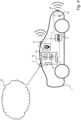
- Fig. 1 illustrates a schematic perspective top view of a vehicle 1 comprising an Automated Driving System (ADS).
- the ADS comprises one or more ADS features that are preferably a level 2 feature or higher according to SAE J3016 levels of driving automation for on-road vehicles.
- an ADS feature may be in the form of an autopilot feature, a traffic jam pilot, a highway pilot, or any other SAE J3016 level 2+ ADS feature.
- the vehicle 1 may also be referred to as the ego-vehicle.
- the vehicle 1 comprises a control system 10 for controlling a driver support function (i.e. an ADS feature) for autonomously maneuvering the vehicle 1 according to several embodiments and aspects of the present disclosure.
- the control system 10 may be a part of the overall ADS architecture of the vehicle, and may accordingly be a module or component of the ADS.
- the control system 10 of the vehicle 1 comprises control circuitry 11 or processing circuitry 11 configured to obtain data comprising information about the surrounding environment of the vehicle 1.
- the vehicle is also provided with a localization system 5 which in communication with the control system 10 are configured to provide an estimation of the vehicle's 1 state or pose i.e. vehicle's geographical position and heading on the road portion 24.
- the term obtaining is herein to be interpreted broadly and encompasses receiving, retrieving, collecting, acquiring, and so forth.
- the state of the vehicle in the context of this disclosure can be construed as having three physical states, namely the longitude, the latitude and the heading of the vehicle.
- the longitude and the latitude are defined with respect to a geographical coordinate system such as the Cartesian coordinate system and indicate the longitudinal position and lateral position of the vehicle on the road portion.
- the heading of the vehicle indicates the compass direction of the vehicle with respect to the geographical north 120 and is typically understood as an angle ( ⁇ ) between a vector 100 of a forward-orientation of the vehicle and a center line 110 extending from the vehicle towards the geographical north.
- the state of the vehicle may also be referred to as a pose of the vehicle.
- the pose is in some embodiments represented by a 2D Cartesian position and a yaw of the vehicle (x, y, ⁇ ). However, in some embodiments, the pose is a 6D pose where the position is defined by a 3D Cartesian position and the orientation is defined by a roll, pitch, and yaw of the vehicle.
- Fig. 1 shows the ego-vehicle 1 travelling on a portion 24 of a road.
- the road is in the form of a carriage way having four lanes 101-104, and the road portion 24 is a portion of the carriage way.
- the road may be any other type of road e.g. a highway with dual carriageways.
- the road may also be a motorway, freeway or expressway.
- the road may also be a country road, rural road or any other carriageway.
- the road may have a plurality of lanes such as more than one lane in the same travelling direction e.g. two or more lanes or at least one lane in each travelling direction as is usually the case for rural roads.
- the control system 10 of vehicle 1 is configured to determine the geographical position and heading of the vehicle on the road portion 24 based on data from the localization system 5 comprising positioning data indicating a pose, i.e. position and orientation, of the vehicle on the road portion 24, map data associated with the road portion 24 and sensor data obtained by the from a perception system i.e. sensor system 6 of the vehicle 1.
- the vehicle may utilize a localization system 5 in the form of a suitable satellite based positioning systems, such as either one of a GNSS or a corresponding regional system such as e.g. a GPS, Globalnaya Navigazionnaya Sputnikovayassela (GLONASS), Galileo, Beidou, etc.
- the localization system 5 may comprise or be associated with an HD-map module.
- An HD-map is in the present context to be understood as map comprising data with highly accurate and realistic representations of the road travelled upon by the vehicle 1.
- HD-maps may be understood as maps that are particularly built for autonomous driving purposes. These maps have an extremely high precision, oftentimes at a centimeter-level.
- the maps generally contain information such as where the lanes are, where the road boundaries are, where the curves are, how high the curves are, and so forth.
- the control system 10 may in various aspects and embodiments comprise or be associated with an Inertial Measurement Unit (IMU).
- IMU Inertial Measurement Unit
- An IMU may be understood as a device configured to detect linear acceleration using one or more accelerometers and rotational rate using one or more gyroscopes.
- the sensor data may be in the form of sensor data obtained from the IMU.
- the output from the IMU is then used to estimate a change in the vehicle's pose over time.
- the prediction of the vehicle's pose may be estimated based on a vehicle motion model together with motion sensor data (e.g. data from accelerometers and gyroscopes, which will herein collectively be referred to as motion sensors).
- the obtained sensor data may additionally comprise information about a state of one or more other external vehicles in the surrounding environment of the ego-vehicle, lane marker geometry on the two or more lanes of the portion 24 of the road, lane marker 241-243 type (e.g. solid, dashed, double marker, etc.) on the portion 24 of the road, traffic sign information 245, road barrier information, etc.
- lane marker geometry on the two or more lanes of the portion 24 of the road
- lane marker 241-243 type e.g. solid, dashed, double marker, etc.
- the prediction of the pose of the vehicle performed by the control system 10 may comprise using linear or non-linear filtering e.g. by using a Bayesian filter or a combination of multiple Bayesian filters.
- each Bayesian filter may be one of Kalman Filter, Extended Kalman Filter (EKF), Unscented Kalman Filter (UKF), Cubature Kalman Filter (CKF), and Particle Filter (PF).
- EKF Extended Kalman Filter
- UDF Unscented Kalman Filter
- CKF Cubature Kalman Filter
- PF Particle Filter
- the selection of the Bayesian filters may be based on design factors or quality of obtained sensor data e.g. the linearity of the sensor measurement models which may control the use of suitable filters or filter combinations for different sensors.
- the localization system 5 of the vehicle obtains a GNSS position of the vehicle 1 on the road portion 24.
- This position is marked as an initial position "A" of the vehicle 1 and a single filter comprising a Bayesian filter or a combination of Bayesian filters are initialized based on the initial position of vehicle 1 as well as the HD-map data of the road portion 24 together with the sensor data to predict the state of the vehicle 1 of the road portion.
- the obtained positioning data may comprise an initial longitude, initial latitude and an initial heading of the vehicle 1 connected to the initial GNSS position "A" of the vehicle.
- the GNSS data is usually associated with an uncertainty "AA" indicated by the dashed circle in Fig. 1 .
- each filter 201-204 may also be referred to as a hypothesis.
- Each hypothesis therefore is an estimation of the pose or state of the vehicle 1 on a designated lane among the plurality of lanes 101-104 of the road portion 24.
- the inventive method and system presented here therefore scrutinizes each hypothesis to select a most promising hypothesis indicative of the most accurate state of the vehicle on the road portions.
- each filter by initializing a filter 201-204 per lane 101-104 on the road portion 24, each filter continuously provides an estimation of the state of the vehicle 1 on its designated lane based on the positioning data, obtained sensor data and the HD-map data.
- Each filter may comprise a Bayesian filter or a combination of Bayesian filters. This way, the most accurate initialized filter amongst the plurality of initialized filters 201-204 can be identified and selected which in turn will indicate the most accurate pose of the vehicle 1 on the road portion 24.
- the initial longitudinal position, initial later position and initial heading (initial pose) comprised in the positioning data connected to the initial position "A" of the vehicle may be obtained from a satellite positioning module, wherein the satellite positioning module may use a Kalman filter or any variants of a Kalman filter such as an extended Kalman filter, an unscented Kalman filter, or a cubature Kalman filter, to continuously estimate the vehicle's pose with inputs of GNSS data, and a predefined motion model of the vehicle.
- a Kalman filter or any variants of a Kalman filter such as an extended Kalman filter, an unscented Kalman filter, or a cubature Kalman filter, to continuously estimate the vehicle's pose with inputs of GNSS data, and a predefined motion model of the vehicle.
- the motion model may be used together with the velocity and/or acceleration data e.g. as obtained from the IMU to predict the vehicle's pose.
- the continuously-obtained positioning data e.g. GNSS data may be applied to the Kalman filter to further estimate and update the vehicle's pose.
- An output of the satellite positioning module is geodetic vehicle pose, including the initial heading, initial longitude, initial latitude, or in some embodiments an initial altitude of the vehicle.
- a pose converter may be used to transform the initial vehicle pose (output of the satellite positioning module) from geodetic coordinates to a local Cartesian coordinate system.
- the initial vehicle pose can be represented as a longitudinal position, a lateral position, and a heading.
- the filter initialization is designed to be a continuous process for controlling the ADS feature of the ego-vehicle 1 and it is possible that in some scenarios, all or some of the initialized filters and their respective pose estimations will be terminated and a filter re-initialization in all or some of the lanes will be repeated.
- the inventors have further realized that by using a data-driven approach comprising the use of machine learning (ML) algorithms to identify and select the most promising initialized filter out of the plurality of initialized filters of a multi-lane road, the possibilities of accurately estimating the state of the vehicle on the road portion 24 improves significantly.
- the data-driven approach of the present disclosure is much more scalable and easier to maintain than any rule-based approach or any algorithm based on human intuition.
- hypothesis-inference algorithms and methods according to the present disclosure comprise machine learning algorithms used to influence and promote behavior that increases the possibility for accurately estimating the state of the vehicle in various scenarios including corner case or edge case scenarios involving multiple environmental variables or conditions happening simultaneously or outside the conventional levels.
- Trained machine learning algorithms in the present context may comprise supervised machine learning algorithms, trained, tested and verified based on conventional real-world data which is obtained through driving the vehicle 1 on various types of roads under a variety of environmental conditions and for suitable periods of time to collect and evaluate the data sets for various scenarios.
- the process of training the ML algorithm may comprises pre-processing, training, testing, and validating phases.
- HD-map data, positioning data, various sensor measurements including camera, radar, LIDAR, GNSS, IMU, pose of other external vehicles in the surrounding environment of the ego-vehicle 1, geometry and type of lane markers, traffic signs and traffic information, road barriers, weather forecast, etc. may be employed as input data for training the ML algorithm.
- reference data also referred to as "ground-truth" data from the real-world driving data collection which include the actual poses and trajectories of the ego-vehicle may be used.
- unsupervised machine learning algorithms may be used for at least part of the determination of the most accurate hypothesis.
- parameters of the trained supervised machine learning algorithm may be used as the initial states for a continuous unsupervised machine learning model based on the large scale dataset.
- the sensor measurements (e.g. state of one or more other external vehicles in the surrounding environment of the vehicle, lane marker geometry, lane marker type, traffic sign information, road barrier information, IMU data etc.) acquired by the sensor devices are converted into a series of quality measures. This may include associating one or more sensor data point(s) in the obtained sensor data to a corresponding map-element of the obtained map data on the HD-map. To perform such as association of sensor measurements to the map data, both the map elements and the sensor measurements may be converted into a same coordinate system based on the believed pose of the ego vehicle.
- each association cost is normalized based on the number of sensor data points that were used to provide a normalized similarity score(s) between the associated obtained map data and the obtained sensor data.
- the normalization may be performed by means of known approaches in the art e.g. by using a Chi-square distribution, with the number of sensor data points corresponding to the degrees of freedom of the Chi-square distribution.
- the normalized similarity scores may also be referred to as "measurement model qualities" or simply as “model qualities” herein, each measurement model quality being indicative of the similarity between the HD-map elements and perceived sensor data points e.g. sensor measurements of the lane markers relative to each initialized filter 201-204.
- Each measurement source may have its own model and thus its own measurement model quality.
- lane marker geometry as a feature represents how well the geometry of the lane markers perceived by the sensors of the vehicle 1 follow the expected geometry as displayed by the HD-map.
- Using a Chi-square normalization ensures that all model qualities have similar magnitudes, regardless of their number of sensor data points. This way, it is easier to combine model qualities together and compare hypotheses.
- the model qualities may be obtained at a frequency of 40 Hz, however the model qualities may be obtained at any other suitable frequencies.
- the model qualities are used for determining one or more multivariate time-series data 201 based on the determined one or more normalized similarity score(s), wherein each multivariate time-series data may be attributed to a corresponding initialized filter among the plurality of initialized filters.
- the multivariate time-series it is meant a time-series in which each data point is multi-dimensional.
- the number of one or more multivariate time-series data equals "n" which is also the number of active hypotheses.
- n would be equal to 4, since there are 4 lanes on the road portion and each lane has a designated initialized hypothesis 201-204.
- the number of hypothesis and the attributed input 201 may vary accordingly depending on each scenario.
- the input 201to the machine learning algorithm 200 comprises multivariate time- series data, MTS
- t i ⁇ 1 n , for "i" being the number of active hypotheses at a current time step "t", wherein i 1, ..., n .
- Determination of the multivariate time-series data may be done based on raw time-series data, or it may be done using some feature extraction or transformation method.
- features that can be extracted from time-series data of the model qualities may be temporal averages, mean of values, the variance, standard deviation, the mode of the data or combinations or aggregations of the model qualities.
- one of the features may be constructed by taking the mean of the two lane marker type model qualities temporally and averaging them into one value.
- Another feature may be the average variance for all model qualities until a given time step. Any other examples of extraction of features from the model qualities than the ones mentioned above may similarly be performed.
- the feature extraction or transformation methods may be any of the known methods or processes in the art e.g.
- t i ⁇ 1 n may be a vector of dimension t ⁇ m , wherein m equals the number of features obtained from the quality models.
- the trained machine learning algorithm in several embodiments and aspects may comprise a supervised machine learning classifier 205, also referred to as a probabilistic classifier herein.
- various probabilistic classifiers known in the art may be used such as a Gaussian Naive Bayes, Logistic Regression, Canonical Interval Forest (a state-of-the-art model for multivariate time-series classification), Linear Support Vector Classifier, Kernel Support Vector Classifier, tree ensemble classifiers such as Gradient Boosting Classifier (a popular and widely used model) or Random Forest Classifier, etc.
- Each of the above-mentioned machine learning probabilistic classifiers 205 are accordingly trained and evaluated to be implemented in the hypothesis inference algorithm presented in this disclosure.
- a confidence probability value 203 for each initialized filter of the plurality of initialized filters may be determined by means of the trained probabilistic classifier 205.
- the confidence probability values 203 in Fig. 2 comprises "n" probability values p 1 , p 2 , ..., p n , each calculated for one of the "n" active initialized hypothesis based on the input data MTS
- the supervised probabilistic classifier may be applied to each hypothesis of the plurality of hypotheses at given time steps "t".
- the input fed into the probabilistic classifier are time-dependent features of model qualities i.e. the one or more multivariate time-series data, MTS
- the input data may also be referred to as a driving sequence herein, each driving sequence comprising the one or more concurrent multivariate time-series data, each multivariate time-series data being attributed to its corresponding initialized filter.
- the output of the probabilistic classifier is a floating probability value between "0" and "1" for each initialized hypothesis.
- various features extracted from the time-series data of the model qualities as explained earlier may be fed into the supervised probabilistic classifier in order to calculate the confidence probability values for each of the hypotheses.
- the calculated confidence probability value for each hypothesis i.e. initialized filter is an indicative of accuracy of that specific hypothesis representing the state of the ego vehicle 1 on the road portion.
- the trained machine learning algorithm ensures that highest probable hypothesis is selected.
- This task is fulfilled by a function 207 comprised in the trained machine learning algorithm for assessing the confidence in selecting the most accurate initialized hypothesis based on the output of the probabilistic classifier.
- the trigger function may also be referred to as a trigger function 207 herein.
- the trigger function may be a binary function, providing a "true” output class 217 which signifies that a hypothesis is correct, and a "false” output class 219 which signifies that a hypothesis is incorrect.
- the probabilistic outputs of the probabilistic classifier fed into the trigger function would lead to a belief of the trigger function expressing if a hypothesis is part of the "true" output class or not.
- the purpose of the trigger function is deciding if the output from the probabilistic classifier is reliable enough, i.e. "true” output class 217, that it should make a prediction, i.e. selection, of the most accurate hypothesis.
- the trigger function may comprise a "reject" or "false” output class 219 functionality. That is, where the trigger function may not reach a prediction based on the outputs received from the probability classifier. In these scenarios the trigger function 207 is configured to wait for more data to be received from the probabilistic classifier. The time 213 shown in Fig.
- the trigger function 207 is implemented by providing a loop of gathering data, evaluating hypotheses, and then either outputting a selection or gathering more data. If the trigger function 207 deems the prediction of the single initialized filter to be reliable enough, then that hypothesis with highest probability is selected as the output 215 of the machine learning algorithm 200.
- the multivariate time series data may be segmented into driving sequences of a certain time length e.g. 30 seconds.
- each driving sequence may be segmented into 1200 time steps with each 1-second time length corresponding to 40 time steps. Accordingly, each driving sequence may be evaluated at certain lengths of time, for instance after 1 second has passed.
- the trigger function may be implemented as a parametrized linear inequality function.
- one of the initialized filters having the highest confidence probability may be selected by the trained machine learning algorithm by comparing the confidence probability values 203 determined for each initialized filter.
- one or more multi-objective optimized coefficient(s) 209 may be introduced to the trigger function 207.
- Each optimized coefficient 209 is indicative of an optimization, e.g. an optimized trade-off, between a readiness performance indicator and an accuracy performance indicator for selecting a single initialized filter as an output of the machine learning algorithm.
- the trigger function may make use of the highest probability output of the classifier i.e. the most probable hypothesis and the second highest probability output of the classifier i.e. the second most probable hypothesis and the difference between these two parameters for evaluating the driving sequences in conjunction with the multi-objective optimized coefficients.
- Other suitable combinations of the outputs of the probabilistic classifier may also be used by the trigger function for selecting the most suitable hypothesis.
- the selected initialized filter is indicative of a current state of the vehicle 1 on the road portion 24.
- a comparison of the probabilistic outputs is what is used to determine the certainty with which a selection of the single initialized filter can be made.
- the outputs of the probabilistic classifier may be sorted 211 by magnitude and used as input to the trigger function whose output determines if a selection should be made at this time step or if the model needs more data, i.e. time, to become more confident in that the highest probable hypothesis, given by the probabilistic classifier, is correct.
- the readiness performance indicator may comprise an availability performance indicator. In some embodiments the readiness performance indicator may comprise an earliness performance indicator.
- the multi-objective optimized coefficients of the trigger function are learned in the training phase of the ML algorithm by optimizing both accuracy and readiness i.e. availability and/or earliness performance measures.
- the earliness performance measure accounts for making a prediction of an initialized filter as fast as possible.
- the availability performance measure accounts for making a prediction of an initialized filter in as many scenarios as possible. In other words, availability is defined as the proportion of driving sequences for which the trigger function provides a "true" output evaluation before the sequence has ended i.e. before a set time step e.g. 1 second and no more evaluations can be made.
- the accuracy performance measure simply accounts for a proportion of correctly-selected single initialized filters by the trained machine learning algorithm i.e.
- a prediction of the most accurate hypothesis for a sequence of input data may be provided as soon as a prediction can be made with certainty, bearing in mind that the more observations are made, the more certain a prediction would be.
- the problem to be solved by the multi-objective algorithm then becomes finding the trade-off between accuracy and readiness.
- the coefficients of the trigger function are established based on the multi-objective optimization in the training phase of the trained machine learning algorithm and the learned coefficients are then used in the test stage to find the best hypothesis in conjunction with the confidence probability values outputted by the probabilistic classifier.
- the multi-objective optimization algorithm may be implemented by using a genetic algorithm and more specifically NSGA2 algorithm.
- NSGA2 stands for (Non-Dominated Sorting Genetic Algorithm 2) which is a genetic algorithm for producing non-dominated solutions in multi-objective optimization.
- an achievement scalarization function as known in the art may be used.
- an optimal solution will be returned based on a vector of weights for accuracy and availability, as well as for accuracy and earliness performance indicators.
- the weights may be set by customizing the preference for accuracy versus availability or earliness.
- the weights may be set by choosing the accuracy performance indicator to be more important than availability and/or earliness measures.
- the training of the probabilistic classifier, the optimization of the trigger function and testing of the complete trained ML model may be an iterative process performed continuously on the obtained data sequences.
- Figs. 3a-b show flowcharts of a method 300 according to various aspects and embodiments of the present disclosure for determining a state of a vehicle 1 on a road portion 24 having two or more lanes 101-104.
- the method 300 comprises obtaining 301 map data, associated with the road portion 24.
- the map data is typically the HD-map data comprising data with highly accurate and realistic representations of the road portion 24.
- the method further comprises obtaining 303 positioning data 402 indicating a pose of the vehicle 1 on the road. More specifically, the initial GNSS position "A" of the vehicle 1 on the road portion 24 is obtained by the localization system 5.
- the positioning data comprises an initial longitude, initial latitude and an initial heading of the vehicle 1 connected to the initial GNSS position "A" of the vehicle.
- the control system 10 is configured to perform the method step of obtaining 305 sensor data from a sensor system i.e. perception system 6 of the vehicle 1 comprising a variety of different sensors such as sensors 6a-6c illustrated for the vehicle 1 of Fig. 4 .
- obtaining 305 sensor data may comprise obtaining 314 at least one of acceleration and velocity of the vehicle 1.
- obtaining the velocity and/or acceleration data as well as a temporal positioning profile of the vehicle 1 an in-lane longitudinal position (x) of the vehicle 1 on the road portion 24 can be determined.
- obtaining 305 sensor data may comprise obtaining 316 the lane marker geometry and a relative distance of the vehicle 1 from the lane markers 241-243 on the road portion 24.
- obtaining 316 the lane marker geometry and a relative distance of the vehicle 1 from the lane markers 241-243 on the road portion 24 may be obtained.
- an in-lane lateral position (y) and in-lane heading 100 of the vehicle 1 on the road portion 24 may be determined.
- the heading of the vehicle can be determined.
- the method further comprises initializing 307 a plurality of filters 201-204 for the road portion wherein one filter is initialized per lane 101-104 of the road portion 24 based on the obtained map data, the obtained positioning data, and the obtained sensor data, wherein each filter 201-204 indicates an estimated state of the vehicle 1 on the road portion 24.
- each filter may employ a Bayesian filter or a combination of different Bayesian filters suitable for the specific scenario to estimate the state of the vehicle 1.
- the initializing 307 of the filters 201-204 per lane 101-104 of the road portion 24 may further comprise, for each filter continuously obtaining 304 the positioning data of the vehicle 1 on the road over time.
- obtaining the initial GNSS position "A" of the vehicle 1 on the road portion 24 is an iterative process and the localization system 5 is configured to repeatedly acquire the initial position "A" over a certain period of time, in predetermined intervals, or based on any other suitable temporal scheme.
- each filter may be initialized based on the determined 307a, 307b longitudinal position (x) and in-lane lateral position (y) and heading 100 of the vehicle 1 on the road portion for each filter 201-204.
- the method continuous to Fig. 3b wherein it is shown that the method 300 further comprises associating 309 one or more sensor data point(s) in the obtained sensor data to a corresponding map-element of the obtained map data. Even further, the method 300 comprises determining 311 one or more normalized similarity score(s) between the associated obtained map data and the obtained sensor data.
- the method 300 further comprises determining 313 one or more multivariate time-series data based on the determined one or more normalized similarity score(s), wherein each multivariate time-series data is attributed to a corresponding initialized filter among the plurality of initialized filters. Additionally, the method comprises providing 315 the one or more multivariate time-series data as input 201 to a trained machine-learning algorithm 200.
- the machine learning algorithm is configured for selecting 319 one of the initialized filters, by comparing the confidence probability values determined for each initialized filter in conjunction with one or more multi-objective optimized coefficient(s) 209, each optimized coefficient being indicative of an optimization, e.g. an optimized trade-off, between a readiness performance indicator and an accuracy performance indicator for selecting a single initialized filter as an output 215 of the machine learning algorithm.
- the output of the machine learning algorithm is indicative of a current state of the vehicle on the road portion.
- the method further comprises controlling 321 the ADS feature of the vehicle based on the selected initialized filter.
- the method 300 may further comprise obtaining 323 a signal indicative of a desired activation of the ADS feature.
- Controlling 321 the ADS feature may comprise activating 325 the ADS feature after the selection of the initialized filter has been made and using the selected initialized filter to indicate the vehicle's state on the road portion 24.
- controlling 321 the ADS feature may comprise at least controlling 321 one or more of acceleration, steering, and braking of the vehicle.
- the method 300 may further comprise determining 311 the one or more similarity score(s) between the associated obtained map data and the obtained sensor data by computing 327 an association cost value for each sensor data point of the one or more sensor data point(s) associated to a corresponding map element and selecting 329 a sensor data point and map-element combination having the smallest association cost value.
- the method 300 may further comprise determining 313 the one or more multivariate time-series data based on the determined one or more normalized similarity score(s) by obtaining 331 one or more time-dependent feature(s) of each determined normalized similarity score.
- Executable instructions for performing these functions are, optionally, included in a non-transitory computer-readable storage medium or other computer program product configured for execution by one or more processors.
- the trained machine learning algorithm may further be configured for sorting 333 the determined confidence probability values for the plurality of the initialized filters based on the confidence level or magnitude of each determined confidence probability value.
- the readiness performance indicator may comprise an availability performance indicator comprising a proportion of the one or more multivariate time-series data for which a selection of a single initialized filter is performed by the trained machine learning algorithm, i.e. the trigger function.
- the availability performance measure accounts for making a prediction of an initialized filter in as many scenarios as possible.
- selection of a single initialized filter for a proportion of the one or more multivariate time-series data may be performed within or before a set period of time, as discussed earlier with respect to time steps.
- the readiness performance indicator may comprise an earliness performance indicator comprising an average fraction passed of the one or more multivariate time-series data before a selection of a single initialized filter is performed by the trained machine learning algorithm i.e. the trigger function.
- the earliness performance measure accounts for making a prediction of an initialized filter as fast as possible.
- the accuracy performance indicator may comprise a proportion of correctly-selected single initialized filters by the trained machine learning algorithm, i.e. the trigger function, being indicative of the current state of the vehicle on the road portion.
- the accuracy performance measure simply accounts for a proportion of correctly-selected single initialized filters.
- Fig. 4 is a schematic side view of a vehicle 1 comprising a control system 10 (control device 10) for determining a vehicle pose.
- the vehicle 1 further comprises a perception system 6 and a localization system 5.
- a perception system 6 is in the present context to be understood as a system responsible for acquiring raw sensor data from on sensors 6a, 6b, 6c such as cameras, LIDARs and RADARs, ultrasonic sensors, and converting this raw data into scene understanding.
- the vehicle 1 has at least one vehicle-mounted camera 6c for capturing images of (at least a portion of) a surrounding environment of the vehicle.
- the localization system 5 is configured to monitor a geographical position and heading of the vehicle, and may in the form of a Global Navigation Satellite System (GNSS), such as a GPS. However, the localization system may alternatively be realized as a Real Time Kinematics (RTK) GPS in order to improve accuracy.
- GNSS Global Navigation Satellite System
- RTK Real Time Kinematics
- the vehicle 1 is assumed to have access to a digital map (e.g. a HD-map), either in the form of a locally stored digital map or via a remote data repository accessible via an external communication network 20 (e.g. as a data stream).
- the access to the digital map may for example be provided by the localization system 5.
- the control system 10 comprises one or more processors 11, a memory 12, a sensor interface 13 and a communication interface 14.
- the processor(s) 11 may also be referred to as a control circuit 11 or control circuitry 11 or processing circuitry 11.
- the control circuit 11 is configured to execute instructions stored in the memory 12 to perform a method for determining a state of an ADS-equipped vehicle on a road portion having one or more lanes according to any one of the embodiments disclosed herein.
- the processing circuitry 11 is configured to perform the method steps of the method 300 in Figs. 3a-b and with reference to Fig. 2 to select a single initialized filter by the ML algorithm on the multi-lane 101-104 stretch of road 24.
- the memory 12 of the control device 10 can include one or more (non-transitory) computer-readable storage mediums, for storing computer-executable instructions, which, when executed by one or more computer processors 11, for example, can cause the computer processors 11 to perform the techniques described herein.
- the memory 12 optionally includes high-speed random access memory, such as DRAM, SRAM, DDR RAM, or other random access solid-state memory devices; and optionally includes non-volatile memory, such as one or more magnetic disk storage devices, optical disk storage devices, flash memory devices, or other non-volatile solid-state storage devices.
- the vehicle 1 may be connected to external network(s) 20 via for instance a wireless link (e.g. for retrieving map data).
- a wireless link e.g. for retrieving map data
- the same or some other wireless link may be used to communicate with other external vehicles in the vicinity of the vehicle or with local infrastructure elements.
- Cellular communication technologies may be used for long range communication such as to external networks and if the cellular communication technology used have low latency it may also be used for communication between vehicles, vehicle to vehicle (V2V), and/or vehicle to infrastructure, V2X.
- Examples of cellular radio technologies are GSM, GPRS, EDGE, LTE, 5G, 5G NR, and so on, also including future cellular solutions.
- LAN Wireless Local Area
- ETSI is working on cellular standards for vehicle communication and for instance 5G is considered as a suitable solution due to the low latency and efficient handling of high bandwidths and communication channels.
- a non-transitory computer-readable storage medium storing one or more programs configured to be executed by one or more processors of a vehicle control system, the one or more programs comprising instructions for performing the method according to any one of the above-discussed embodiments.
- a computer program product comprising instructions which, when the program is executed by one or more processors of a processing system, causes the processing system to carry out the method according to any one of the embodiments of the method of the present disclosure.
- a cloud computing system can be configured to perform any of the methods presented herein.
- the cloud computing system may comprise distributed cloud computing resources that jointly perform the methods presented herein under control of one or more computer program products.
- a computer-accessible medium may include any tangible or non-transitory storage media or memory media such as electronic, magnetic, or optical media-e.g., disk or CD/DVD-ROM coupled to computer system via bus.
- tangible and non-transitory are intended to describe a computer-readable storage medium (or “memory”) excluding propagating electromagnetic signals, but are not intended to otherwise limit the type of physical computer-readable storage device that is encompassed by the phrase computer-readable medium or memory.
- the terms “non-transitory computer-readable medium” or “tangible memory” are intended to encompass types of storage devices that do not necessarily store information permanently, including for example, random access memory (RAM).
- Program instructions and data stored on a tangible computer-accessible storage medium in non-transitory form may further be transmitted by transmission media or signals such as electrical, electromagnetic, or digital signals, which may be conveyed via a communication medium such as a network and/or a wireless link.
- transmission media or signals such as electrical, electromagnetic, or digital signals, which may be conveyed via a communication medium such as a network and/or a wireless link.
- the processor(s) 11 may be or include any number of hardware components for conducting data or signal processing or for executing computer code stored in memory 12.
- the device 10 may have an associated memory 12, and the memory 12 may be one or more devices for storing data and/or computer code for completing or facilitating the various methods described in the present description.
- the memory may include volatile memory or non-volatile memory.
- the memory 12 may include database components, object code components, script components, or any other type of information structure for supporting the various activities of the present description. According to an exemplary embodiment, any distributed or local memory device may be utilized with the systems and methods of this description.
- the memory 12 is communicably connected to the processor 11 (e.g., via a circuit or any other wired, wireless, or network connection) and includes computer code for executing one or more processes described herein.
- the ego-vehicle 1 further comprises a sensor interface 13 which may also provide the possibility to acquire sensor data directly or via dedicated sensor control circuitry 6 in the vehicle.
- the vehicle 1 also comprises a communication/antenna interface 14 which may further provide the possibility to send output to a remote location (e.g. remote operator or control centre) by means of an antenna 8.
- some sensors in the vehicle may communicate with the control device 10 using a local network setup, such as CAN bus, I2C, Ethernet, optical fibres, and so on.
- the communication interface 14 may be arranged to communicate with other control functions of the vehicle and may thus be seen as control interface also; however, a separate control interface (not shown) may be provided.
- Local communication within the vehicle may also be of a wireless type with protocols such as WiFi, LoRa, Zigbee, Bluetooth, or similar mid/short range technologies.
- parts of the described solution may be implemented either in the vehicle, in a system located external the vehicle, or in a combination of internal and external the vehicle; for instance in a server in communication with the vehicle, a so called cloud solution.
- the ML algorithm may be implemented in the processing circuitry 11.
- sensor data may be sent to an external system, wherein the external system comprises the ML algorithm to select the single initialized filter.
Landscapes
- Engineering & Computer Science (AREA)
- Radar, Positioning & Navigation (AREA)
- Remote Sensing (AREA)
- Automation & Control Theory (AREA)
- Physics & Mathematics (AREA)
- General Physics & Mathematics (AREA)
- Human Computer Interaction (AREA)
- Transportation (AREA)
- Mechanical Engineering (AREA)
- Theoretical Computer Science (AREA)
- Computer Networks & Wireless Communication (AREA)
- Software Systems (AREA)
- Multimedia (AREA)
- Artificial Intelligence (AREA)
- Computer Vision & Pattern Recognition (AREA)
- Data Mining & Analysis (AREA)
- Evolutionary Computation (AREA)
- Medical Informatics (AREA)
- Computing Systems (AREA)
- General Engineering & Computer Science (AREA)
- Mathematical Physics (AREA)
- Traffic Control Systems (AREA)
Claims (15)
- Procédé de détermination d'un état d'un véhicule sur une portion de route ayant deux voies ou plus, le véhicule comprenant une fonction de système de conduite automatisée, ADS, le procédé comprenant :l'obtention de données cartographiques associées à la portion de route ;l'obtention de données de positionnement indiquant une pose du véhicule sur la route ;l'obtention de données de capteur à partir d'un système de capteurs du véhicule ;l'initialisation d'une pluralité de filtres pour la portion de route, dans lequel un filtre est initialisé par voie de la portion de route sur la base des données cartographiques obtenues, des données de positionnement obtenues et des données de capteur obtenues, dans lequel chaque filtre indique un état estimé du véhicule sur la portion de route ;l'association d'un ou de plusieurs points de données de capteur dans les données de capteur obtenues à un élément cartographique correspondant des données cartographiques obtenues ;la détermination d'un ou de plusieurs scores de similarité normalisés entre les données cartographiques obtenues associées et les données de capteur obtenues ; caractérisé en ce que le procédé comprend en outre :la détermination d'une ou de plusieurs données de séries chronologiques multivariées sur la base des un ou plusieurs scores de similarité normalisés déterminés, dans lequel chaque donnée de série chronologique multivariée est attribuée à un filtre initialisé correspondant parmi la pluralité de filtres initialisés ;la fourniture d'une ou de plusieurs données de séries chronologiques multivariées en tant qu'entrée à un algorithme d'apprentissage automatique entraîné ; dans lequel l'algorithme d'apprentissage automatique entraîné est configuré pour :déterminer une valeur de probabilité de confiance pour chaque filtre initialisé de la pluralité de filtres initialisés au moyen d'un classificateur probabiliste ;la sélection de l'un des filtres initialisés, en comparant les valeurs de probabilité de confiance déterminées pour chaque filtre initialisé en conjonction avec un ou plusieurs coefficients optimisés multi-objectifs, chaque coefficient optimisé étant indicatif d'une optimisation entre un indicateur de performance de préparation et un indicateur de performance de précision pour sélectionner un filtre initialisé unique en tant que sortie de l'algorithme d'apprentissage automatique indicatif d'un état actuel du véhicule sur la portion de route ; dans lequel le procédé comprend en outre :la commande de la fonction ADS du véhicule sur la base du filtre initialisé sélectionné.
- Procédé selon la revendication 1, dans lequel chaque filtre initialisé est l'un d'un filtre bayésien et d'une combinaison de multiples filtres bayésiens.
- Procédé selon la revendication 2, dans lequel chaque filtre bayésien est l'un du filtre de Kalman, du filtre de Kalman étendu, EKF, du filtre de Kalman non parfumé, UKF, du filtre de Kalman à cubature, CKF, et du filtre à particules, PF.
- Procédé selon l'une quelconque des revendications 1 ou 2, dans lequel les données de capteur obtenues comprennent des informations sur un état d'un ou de plusieurs autres véhicules dans l'environnement environnant du véhicule, la géométrie du marqueur de voie, le type de marqueur de voie, des informations sur les panneaux de signalisation, des informations sur les barrières routières et des données d'unité de mesure inertielle, IMU.
- Procédé selon l'une quelconque des revendications précédentes, dans lequel le procédé comprend en outre la détermination d'un ou de plusieurs scores de similarité normalisés entre les données cartographiques obtenues associées et les données de capteur obtenues :en calculant une valeur de coût d'association pour chaque point de données de capteur des un ou plusieurs points de données de capteur associés à un élément cartographique correspondant ; eten sélectionnant un point de données de capteur et une combinaison d'éléments cartographiques ayant la plus petite valeur de coût d'association.
- Procédé selon l'une quelconque des revendications précédentes, dans lequel le procédé comprend en outre la détermination d'une ou de plusieurs données de séries chronologiques multivariées sur la base des un ou plusieurs scores de similarité normalisés déterminés en obtenant une ou plusieurs caractéristiques dépendantes du temps de chaque score de similarité normalisé déterminé.
- Procédé selon l'une quelconque des revendications précédentes, dans lequel l'algorithme d'apprentissage automatique entraîné est en outre configuré pour :
trier les valeurs de probabilité de confiance déterminées pour la pluralité des filtres initialisés sur la base du niveau de confiance de chaque valeur de probabilité de confiance déterminée. - Procédé selon l'une quelconque des revendications précédentes, dans lequel pour chaque coefficient optimisé :l'indicateur de performance de préparation comprend l'un quelconque d'un indicateur de performance de disponibilité comprenant une proportion des une ou plusieurs données de séries chronologiques multivariées pour lesquelles une sélection d'un filtre initialisé unique est exécutée par l'algorithme d'apprentissage automatique entraîné ; et d'un indicateur de performance de précocité comprenant une fraction moyenne transmise des une ou plusieurs données de séries chronologiques multivariées avant qu'une sélection d'un filtre initialisé unique ne soit exécutée par l'algorithme d'apprentissage automatique entraîné ; eten outre pour chaque coefficient optimisé :
l'indicateur de précision de performance comprend une proportion de filtres initialisés uniques correctement sélectionnés par l'algorithme d'apprentissage automatique entraîné, étant indicatif de l'état actuel du véhicule sur la portion de route. - Procédé selon l'une quelconque des revendications précédentes, dans lequel les données cartographiques comprennent des données cartographiques HD.
- Support de stockage lisible par ordinateur stockant un ou plusieurs programmes configurés pour être exécutés par un ou plusieurs processeurs d'un système de traitement embarqué, les un ou plusieurs programmes comprenant des instructions pour exécuter le procédé selon l'une quelconque des revendications précédentes.
- Système de détermination d'un état d'un véhicule sur une portion de route ayant deux voies ou plus, le véhicule comprenant une fonction de système de conduite automatisée, ADS, et le système comprenant un circuit de traitement configuré pour :obtenir des données cartographiques associées à la portion de route ;obtenir des données de positionnement indiquant une pose du véhicule sur la route ;obtenir des données de capteur à partir d'un système de capteurs du véhicule ;initialiser une pluralité de filtres pour la portion de route, dans lequel un filtre est initialisé par voie de la portion de route sur la base des données cartographiques obtenues, des données de positionnement obtenues et des données de capteur obtenues, dans lequel chaque filtre indique un état estimé du véhicule sur la portion de route ;associer un ou plusieurs points de données de capteur dans les données de capteur obtenues à un élément cartographique correspondant des données cartographiques obtenues ;déterminer un ou plusieurs scores de similarité normalisés entre les données cartographiques obtenues associées et les données de capteur obtenues ; caractérisé en ce que le circuit de traitement est en outre configuré pour :déterminer une ou plusieurs données de séries chronologiques multivariées sur la base des un ou plusieurs scores de similarité normalisés déterminés, dans lequel chaque donnée de série chronologique multivariée est attribuée à un filtre initialisé correspondant parmi la pluralité de filtres initialisés ;fournir les une ou plusieurs données de séries chronologiques multivariées en tant qu'entrée à un algorithme d'apprentissage automatique entraîné ; dans lequel l'algorithme d'apprentissage automatique entraîné est configuré pour :déterminer une valeur de probabilité de confiance pour chaque filtre initialisé de la pluralité de filtres initialisés au moyen d'un classificateur probabiliste ;sélectionner l'un des filtres initialisés, en comparant les valeurs de probabilité de confiance déterminées pour chaque filtre initialisé en conjonction avec un ou plusieurs coefficients optimisés multi-objectifs, chaque coefficient optimisé étant indicatif d'une optimisation entre un indicateur de performance de préparation et un indicateur de performance de précision pour sélectionner un filtre initialisé unique en tant que sortie de l'algorithme d'apprentissage automatique indicatif d'un état actuel du véhicule sur la portion de route ; dans lequel le circuit de traitement est en outre configuré pour :commander la fonction ADS du véhicule sur la base du filtre initialisé sélectionné.
- Système selon la revendication 11, dans lequel le circuit de traitement est en outre configuré pour :calculer une valeur de coût d'association pour chaque point de données de capteur des un ou plusieurs points de données de capteur associés à un élément cartographique correspondant ; etsélectionner un point de données de capteur et une combinaison d'éléments cartographiques ayant la plus petite valeur de coût d'association.
- Système selon l'une quelconque des revendications 11 ou 12, dans lequel le circuit de traitement est en outre configuré pour :
déterminer une ou plusieurs données de séries chronologiques multivariées sur la base des un ou plusieurs scores de similarité normalisés déterminés en obtenant une ou plusieurs caractéristiques dépendantes du temps de chaque score de similarité normalisé déterminé. - Système selon l'une quelconque des revendications 11 à 13, dans lequel pour chaque coefficient optimisé :l'indicateur de performance de préparation comprend l'un quelconque d'un indicateur de performance de disponibilité comprenant une proportion des une ou plusieurs données de séries chronologiques multivariées pour lesquelles une sélection d'un filtre initialisé unique est exécutée par l'algorithme d'apprentissage automatique entraîné ; et d'un indicateur de performance de précocité comprenant une fraction moyenne transmise des une ou plusieurs données de séries chronologiques multivariées avant qu'une sélection d'un filtre initialisé unique ne soit exécutée par l'algorithme d'apprentissage automatique entraîné ; eten outre pour chaque coefficient optimisé :
l'indicateur de précision de performance comprend une proportion de filtres initialisés uniques correctement sélectionnés par l'algorithme d'apprentissage automatique entraîné, étant indicatif de l'état actuel du véhicule sur la portion de route. - Véhicule comprenant :un ou plusieurs capteurs montés sur véhicule configurés pour surveiller l'environnement environnant du véhicule ;un système de localisation configuré pour surveiller une pose du véhicule sur une route ; etun système selon l'une quelconque des revendications 11 à 14.
Priority Applications (3)
| Application Number | Priority Date | Filing Date | Title |
|---|---|---|---|
| EP22173553.3A EP4279869B1 (fr) | 2022-05-16 | 2022-05-16 | Détermination d'un état d'un véhicule sur une route |
| US18/317,185 US12403933B2 (en) | 2022-05-16 | 2023-05-15 | Determining a state of a vehicle on a road |
| CN202310548852.3A CN117073693A (zh) | 2022-05-16 | 2023-05-16 | 确定道路上的车辆的状态 |
Applications Claiming Priority (1)
| Application Number | Priority Date | Filing Date | Title |
|---|---|---|---|
| EP22173553.3A EP4279869B1 (fr) | 2022-05-16 | 2022-05-16 | Détermination d'un état d'un véhicule sur une route |
Publications (2)
| Publication Number | Publication Date |
|---|---|
| EP4279869A1 EP4279869A1 (fr) | 2023-11-22 |
| EP4279869B1 true EP4279869B1 (fr) | 2024-10-30 |
Family
ID=81654632
Family Applications (1)
| Application Number | Title | Priority Date | Filing Date |
|---|---|---|---|
| EP22173553.3A Active EP4279869B1 (fr) | 2022-05-16 | 2022-05-16 | Détermination d'un état d'un véhicule sur une route |
Country Status (3)
| Country | Link |
|---|---|
| US (1) | US12403933B2 (fr) |
| EP (1) | EP4279869B1 (fr) |
| CN (1) | CN117073693A (fr) |
Families Citing this family (6)
| Publication number | Priority date | Publication date | Assignee | Title |
|---|---|---|---|---|
| DE102020206356A1 (de) * | 2020-05-20 | 2021-11-25 | Robert Bosch Gesellschaft mit beschränkter Haftung | Verfahren zum Ermitteln einer Ausgangspose eines Fahrzeugs |
| US12306316B2 (en) * | 2022-06-30 | 2025-05-20 | Mitsubishi Electric Research Laboratories, Inc. | System and method for controlling a device using a compound probabilistic filter |
| EP4478304A1 (fr) * | 2023-06-13 | 2024-12-18 | Zenseact AB | Estimation de route basée sur un modèle |
| US12545285B2 (en) * | 2023-08-08 | 2026-02-10 | Dish Wireless L.L.C. | Cloud-based automated navigation |
| KR20250084393A (ko) * | 2023-12-04 | 2025-06-11 | 현대자동차주식회사 | 차량 중심과 방향 벡터를 이용한 자율주차 경로 생성 및 추종을 위한 장치 및 방법 |
| US20250200788A1 (en) * | 2023-12-18 | 2025-06-19 | Ford Global Technologies, Llc | Vehicle pose determination |
Citations (1)
| Publication number | Priority date | Publication date | Assignee | Title |
|---|---|---|---|---|
| WO2022081507A1 (fr) * | 2020-10-12 | 2022-04-21 | Nvidia Corporation | Cartes à haute définition et localisation de véhicules routiers |
Family Cites Families (6)
| Publication number | Priority date | Publication date | Assignee | Title |
|---|---|---|---|---|
| US6064320A (en) * | 1997-04-04 | 2000-05-16 | Texas Instruments Incorporated | Automatic vehicle identification system capable of vehicle lane discrimination |
| US20140257686A1 (en) * | 2013-03-05 | 2014-09-11 | GM Global Technology Operations LLC | Vehicle lane determination |
| US8996197B2 (en) * | 2013-06-20 | 2015-03-31 | Ford Global Technologies, Llc | Lane monitoring with electronic horizon |
| US11125566B2 (en) * | 2015-07-16 | 2021-09-21 | Ford Global Technologies, Llc | Method and apparatus for determining a vehicle ego-position |
| US20200232806A1 (en) * | 2019-01-23 | 2020-07-23 | Uber Technologies, Inc | Local map server and multiplexer |
| CN114333335A (zh) * | 2022-03-15 | 2022-04-12 | 成都交大大数据科技有限公司 | 基于轨迹数据的车道级交通状态估计方法、装置及系统 |
-
2022
- 2022-05-16 EP EP22173553.3A patent/EP4279869B1/fr active Active
-
2023
- 2023-05-15 US US18/317,185 patent/US12403933B2/en active Active
- 2023-05-16 CN CN202310548852.3A patent/CN117073693A/zh active Pending
Patent Citations (1)
| Publication number | Priority date | Publication date | Assignee | Title |
|---|---|---|---|---|
| WO2022081507A1 (fr) * | 2020-10-12 | 2022-04-21 | Nvidia Corporation | Cartes à haute définition et localisation de véhicules routiers |
Also Published As
| Publication number | Publication date |
|---|---|
| EP4279869A1 (fr) | 2023-11-22 |
| CN117073693A (zh) | 2023-11-17 |
| US12403933B2 (en) | 2025-09-02 |
| US20230365154A1 (en) | 2023-11-16 |
Similar Documents
| Publication | Publication Date | Title |
|---|---|---|
| EP4279869B1 (fr) | Détermination d'un état d'un véhicule sur une route | |
| US12085403B2 (en) | Vehicle localisation | |
| US20240212319A1 (en) | Classification of objects present on a road | |
| EP4270352B1 (fr) | Contrôle d'un état futur de trafic sur un segment de route | |
| US12227195B2 (en) | Hypothesis inference for vehicles | |
| US12602931B2 (en) | Identification of unknown traffic objects | |
| CN115390868A (zh) | 自动驾驶系统感知的开发 | |
| US12358514B2 (en) | Vehicle pose assessment | |
| EP4261738B1 (fr) | Suivi de voies multi-cibles | |
| US11983918B2 (en) | Platform for perception system development for automated driving system | |
| US12240487B2 (en) | Platform for perception system development for automated driving systems | |
| US20250148372A1 (en) | Automated data annotation for machine learning applications | |
| US20240328793A1 (en) | Vehicle localization | |
| US20240135252A1 (en) | Lane-assignment for traffic objects on a road | |
| US20230090338A1 (en) | Method and system for evaluation and development of automated driving system features or functions | |
| JP7313240B2 (ja) | 走行軌道推定方法、車両制御方法及び走行軌道推定装置 | |
| EP4394664A1 (fr) | Génération automatisée de données par des ensembles de réseaux neuronaux | |
| EP4431974A1 (fr) | Génération de représentation d'un environnement environnant d'un véhicule | |
| US20230091986A1 (en) | Method and system for evaluation and development of automated driving system features | |
| CN121959393A (en) | Intermediate level set of sensor fusion |
Legal Events
| Date | Code | Title | Description |
|---|---|---|---|
| PUAI | Public reference made under article 153(3) epc to a published international application that has entered the european phase |
Free format text: ORIGINAL CODE: 0009012 |
|
| STAA | Information on the status of an ep patent application or granted ep patent |
Free format text: STATUS: THE APPLICATION HAS BEEN PUBLISHED |
|
| AK | Designated contracting states |
Kind code of ref document: A1 Designated state(s): AL AT BE BG CH CY CZ DE DK EE ES FI FR GB GR HR HU IE IS IT LI LT LU LV MC MK MT NL NO PL PT RO RS SE SI SK SM TR |
|
| STAA | Information on the status of an ep patent application or granted ep patent |
Free format text: STATUS: REQUEST FOR EXAMINATION WAS MADE |
|
| 17P | Request for examination filed |
Effective date: 20240502 |
|
| RBV | Designated contracting states (corrected) |
Designated state(s): AL AT BE BG CH CY CZ DE DK EE ES FI FR GB GR HR HU IE IS IT LI LT LU LV MC MK MT NL NO PL PT RO RS SE SI SK SM TR |
|
| GRAP | Despatch of communication of intention to grant a patent |
Free format text: ORIGINAL CODE: EPIDOSNIGR1 |
|
| STAA | Information on the status of an ep patent application or granted ep patent |
Free format text: STATUS: GRANT OF PATENT IS INTENDED |
|
| RIC1 | Information provided on ipc code assigned before grant |
Ipc: G06V 20/56 20220101ALI20240521BHEP Ipc: G01C 21/16 20060101ALI20240521BHEP Ipc: G01C 21/30 20060101AFI20240521BHEP |
|
| INTG | Intention to grant announced |
Effective date: 20240611 |
|
| GRAS | Grant fee paid |
Free format text: ORIGINAL CODE: EPIDOSNIGR3 |
|
| GRAA | (expected) grant |
Free format text: ORIGINAL CODE: 0009210 |
|
| STAA | Information on the status of an ep patent application or granted ep patent |
Free format text: STATUS: THE PATENT HAS BEEN GRANTED |
|
| AK | Designated contracting states |
Kind code of ref document: B1 Designated state(s): AL AT BE BG CH CY CZ DE DK EE ES FI FR GB GR HR HU IE IS IT LI LT LU LV MC MK MT NL NO PL PT RO RS SE SI SK SM TR |
|
| REG | Reference to a national code |
Ref country code: GB Ref legal event code: FG4D |
|
| REG | Reference to a national code |
Ref country code: CH Ref legal event code: EP |
|
| P01 | Opt-out of the competence of the unified patent court (upc) registered |
Free format text: CASE NUMBER: APP_54309/2024 Effective date: 20241002 |
|
| REG | Reference to a national code |
Ref country code: DE Ref legal event code: R096 Ref document number: 602022007167 Country of ref document: DE |
|
| REG | Reference to a national code |
Ref country code: IE Ref legal event code: FG4D |
|
| REG | Reference to a national code |
Ref country code: SE Ref legal event code: TRGR |
|
| REG | Reference to a national code |
Ref country code: LT Ref legal event code: MG9D |
|
| REG | Reference to a national code |
Ref country code: NL Ref legal event code: MP Effective date: 20241030 |
|
| PG25 | Lapsed in a contracting state [announced via postgrant information from national office to epo] |
Ref country code: IS Free format text: LAPSE BECAUSE OF FAILURE TO SUBMIT A TRANSLATION OF THE DESCRIPTION OR TO PAY THE FEE WITHIN THE PRESCRIBED TIME-LIMIT Effective date: 20250228 Ref country code: HR Free format text: LAPSE BECAUSE OF FAILURE TO SUBMIT A TRANSLATION OF THE DESCRIPTION OR TO PAY THE FEE WITHIN THE PRESCRIBED TIME-LIMIT Effective date: 20241030 Ref country code: PT Free format text: LAPSE BECAUSE OF FAILURE TO SUBMIT A TRANSLATION OF THE DESCRIPTION OR TO PAY THE FEE WITHIN THE PRESCRIBED TIME-LIMIT Effective date: 20250228 |
|
| PG25 | Lapsed in a contracting state [announced via postgrant information from national office to epo] |
Ref country code: NL Free format text: LAPSE BECAUSE OF FAILURE TO SUBMIT A TRANSLATION OF THE DESCRIPTION OR TO PAY THE FEE WITHIN THE PRESCRIBED TIME-LIMIT Effective date: 20241030 Ref country code: FI Free format text: LAPSE BECAUSE OF FAILURE TO SUBMIT A TRANSLATION OF THE DESCRIPTION OR TO PAY THE FEE WITHIN THE PRESCRIBED TIME-LIMIT Effective date: 20241030 |
|
| REG | Reference to a national code |
Ref country code: AT Ref legal event code: MK05 Ref document number: 1737259 Country of ref document: AT Kind code of ref document: T Effective date: 20241030 |
|
| PG25 | Lapsed in a contracting state [announced via postgrant information from national office to epo] |
Ref country code: BG Free format text: LAPSE BECAUSE OF FAILURE TO SUBMIT A TRANSLATION OF THE DESCRIPTION OR TO PAY THE FEE WITHIN THE PRESCRIBED TIME-LIMIT Effective date: 20241030 |
|
| PG25 | Lapsed in a contracting state [announced via postgrant information from national office to epo] |
Ref country code: ES Free format text: LAPSE BECAUSE OF FAILURE TO SUBMIT A TRANSLATION OF THE DESCRIPTION OR TO PAY THE FEE WITHIN THE PRESCRIBED TIME-LIMIT Effective date: 20241030 |
|
| PG25 | Lapsed in a contracting state [announced via postgrant information from national office to epo] |
Ref country code: NO Free format text: LAPSE BECAUSE OF FAILURE TO SUBMIT A TRANSLATION OF THE DESCRIPTION OR TO PAY THE FEE WITHIN THE PRESCRIBED TIME-LIMIT Effective date: 20250130 |
|
| PG25 | Lapsed in a contracting state [announced via postgrant information from national office to epo] |
Ref country code: LV Free format text: LAPSE BECAUSE OF FAILURE TO SUBMIT A TRANSLATION OF THE DESCRIPTION OR TO PAY THE FEE WITHIN THE PRESCRIBED TIME-LIMIT Effective date: 20241030 Ref country code: AT Free format text: LAPSE BECAUSE OF FAILURE TO SUBMIT A TRANSLATION OF THE DESCRIPTION OR TO PAY THE FEE WITHIN THE PRESCRIBED TIME-LIMIT Effective date: 20241030 Ref country code: GR Free format text: LAPSE BECAUSE OF FAILURE TO SUBMIT A TRANSLATION OF THE DESCRIPTION OR TO PAY THE FEE WITHIN THE PRESCRIBED TIME-LIMIT Effective date: 20250131 |
|
| PG25 | Lapsed in a contracting state [announced via postgrant information from national office to epo] |
Ref country code: PL Free format text: LAPSE BECAUSE OF FAILURE TO SUBMIT A TRANSLATION OF THE DESCRIPTION OR TO PAY THE FEE WITHIN THE PRESCRIBED TIME-LIMIT Effective date: 20241030 |
|
| PG25 | Lapsed in a contracting state [announced via postgrant information from national office to epo] |
Ref country code: RS Free format text: LAPSE BECAUSE OF FAILURE TO SUBMIT A TRANSLATION OF THE DESCRIPTION OR TO PAY THE FEE WITHIN THE PRESCRIBED TIME-LIMIT Effective date: 20250130 |
|
| PG25 | Lapsed in a contracting state [announced via postgrant information from national office to epo] |
Ref country code: SM Free format text: LAPSE BECAUSE OF FAILURE TO SUBMIT A TRANSLATION OF THE DESCRIPTION OR TO PAY THE FEE WITHIN THE PRESCRIBED TIME-LIMIT Effective date: 20241030 |
|
| PGFP | Annual fee paid to national office [announced via postgrant information from national office to epo] |
Ref country code: DE Payment date: 20250415 Year of fee payment: 4 |
|
| PG25 | Lapsed in a contracting state [announced via postgrant information from national office to epo] |
Ref country code: DK Free format text: LAPSE BECAUSE OF FAILURE TO SUBMIT A TRANSLATION OF THE DESCRIPTION OR TO PAY THE FEE WITHIN THE PRESCRIBED TIME-LIMIT Effective date: 20241030 |
|
| PG25 | Lapsed in a contracting state [announced via postgrant information from national office to epo] |
Ref country code: EE Free format text: LAPSE BECAUSE OF FAILURE TO SUBMIT A TRANSLATION OF THE DESCRIPTION OR TO PAY THE FEE WITHIN THE PRESCRIBED TIME-LIMIT Effective date: 20241030 |
|
| PG25 | Lapsed in a contracting state [announced via postgrant information from national office to epo] |
Ref country code: RO Free format text: LAPSE BECAUSE OF FAILURE TO SUBMIT A TRANSLATION OF THE DESCRIPTION OR TO PAY THE FEE WITHIN THE PRESCRIBED TIME-LIMIT Effective date: 20241030 |
|
| PG25 | Lapsed in a contracting state [announced via postgrant information from national office to epo] |
Ref country code: SK Free format text: LAPSE BECAUSE OF FAILURE TO SUBMIT A TRANSLATION OF THE DESCRIPTION OR TO PAY THE FEE WITHIN THE PRESCRIBED TIME-LIMIT Effective date: 20241030 |
|
| PG25 | Lapsed in a contracting state [announced via postgrant information from national office to epo] |
Ref country code: CZ Free format text: LAPSE BECAUSE OF FAILURE TO SUBMIT A TRANSLATION OF THE DESCRIPTION OR TO PAY THE FEE WITHIN THE PRESCRIBED TIME-LIMIT Effective date: 20241030 |
|
| PG25 | Lapsed in a contracting state [announced via postgrant information from national office to epo] |
Ref country code: IT Free format text: LAPSE BECAUSE OF FAILURE TO SUBMIT A TRANSLATION OF THE DESCRIPTION OR TO PAY THE FEE WITHIN THE PRESCRIBED TIME-LIMIT Effective date: 20241030 |
|
| REG | Reference to a national code |
Ref country code: DE Ref legal event code: R097 Ref document number: 602022007167 Country of ref document: DE |
|
| PLBE | No opposition filed within time limit |
Free format text: ORIGINAL CODE: 0009261 |
|
| STAA | Information on the status of an ep patent application or granted ep patent |
Free format text: STATUS: NO OPPOSITION FILED WITHIN TIME LIMIT |
|
| 26N | No opposition filed |
Effective date: 20250731 |
|
| REG | Reference to a national code |
Ref country code: CH Ref legal event code: H13 Free format text: ST27 STATUS EVENT CODE: U-0-0-H10-H13 (AS PROVIDED BY THE NATIONAL OFFICE) Effective date: 20251223 |
|
| PG25 | Lapsed in a contracting state [announced via postgrant information from national office to epo] |
Ref country code: LU Free format text: LAPSE BECAUSE OF NON-PAYMENT OF DUE FEES Effective date: 20250516 |
|
| PG25 | Lapsed in a contracting state [announced via postgrant information from national office to epo] |
Ref country code: CH Free format text: LAPSE BECAUSE OF NON-PAYMENT OF DUE FEES Effective date: 20250531 |
|
| REG | Reference to a national code |
Ref country code: BE Ref legal event code: MM Effective date: 20250531 |
|
| PG25 | Lapsed in a contracting state [announced via postgrant information from national office to epo] |
Ref country code: MC Free format text: LAPSE BECAUSE OF FAILURE TO SUBMIT A TRANSLATION OF THE DESCRIPTION OR TO PAY THE FEE WITHIN THE PRESCRIBED TIME-LIMIT Effective date: 20241030 |
|
| PGFP | Annual fee paid to national office [announced via postgrant information from national office to epo] |
Ref country code: SE Payment date: 20260316 Year of fee payment: 5 |
|
| PGFP | Annual fee paid to national office [announced via postgrant information from national office to epo] |
Ref country code: GB Payment date: 20260317 Year of fee payment: 5 |
|
| PG25 | Lapsed in a contracting state [announced via postgrant information from national office to epo] |
Ref country code: IE Free format text: LAPSE BECAUSE OF NON-PAYMENT OF DUE FEES Effective date: 20250516 |
|
| PG25 | Lapsed in a contracting state [announced via postgrant information from national office to epo] |
Ref country code: BE Free format text: LAPSE BECAUSE OF NON-PAYMENT OF DUE FEES Effective date: 20250531 |
|
| PG25 | Lapsed in a contracting state [announced via postgrant information from national office to epo] |
Ref country code: FR Free format text: LAPSE BECAUSE OF NON-PAYMENT OF DUE FEES Effective date: 20250531 |