EP4301981B1 - Verfahren und pumpe zur proportionalen dosierung mit geringem durchfluss - Google Patents
Verfahren und pumpe zur proportionalen dosierung mit geringem durchfluss Download PDFInfo
- Publication number
- EP4301981B1 EP4301981B1 EP22709673.2A EP22709673A EP4301981B1 EP 4301981 B1 EP4301981 B1 EP 4301981B1 EP 22709673 A EP22709673 A EP 22709673A EP 4301981 B1 EP4301981 B1 EP 4301981B1
- Authority
- EP
- European Patent Office
- Prior art keywords
- hydraulic machine
- axis
- outlet
- metering pump
- proportional metering
- Prior art date
- Legal status (The legal status is an assumption and is not a legal conclusion. Google has not performed a legal analysis and makes no representation as to the accuracy of the status listed.)
- Active
Links
Images


Classifications
-
- F—MECHANICAL ENGINEERING; LIGHTING; HEATING; WEAPONS; BLASTING
- F04—POSITIVE - DISPLACEMENT MACHINES FOR LIQUIDS; PUMPS FOR LIQUIDS OR ELASTIC FLUIDS
- F04B—POSITIVE-DISPLACEMENT MACHINES FOR LIQUIDS; PUMPS
- F04B9/00—Piston machines or pumps characterised by the driving or driven means to or from their working members
- F04B9/02—Piston machines or pumps characterised by the driving or driven means to or from their working members the means being mechanical
- F04B9/04—Piston machines or pumps characterised by the driving or driven means to or from their working members the means being mechanical the means being cams, eccentrics or pin-and-slot mechanisms
- F04B9/047—Piston machines or pumps characterised by the driving or driven means to or from their working members the means being mechanical the means being cams, eccentrics or pin-and-slot mechanisms the means being pin-and-slot mechanisms
-
- F—MECHANICAL ENGINEERING; LIGHTING; HEATING; WEAPONS; BLASTING
- F04—POSITIVE - DISPLACEMENT MACHINES FOR LIQUIDS; PUMPS FOR LIQUIDS OR ELASTIC FLUIDS
- F04B—POSITIVE-DISPLACEMENT MACHINES FOR LIQUIDS; PUMPS
- F04B13/00—Pumps specially modified to deliver fixed or variable measured quantities
-
- F—MECHANICAL ENGINEERING; LIGHTING; HEATING; WEAPONS; BLASTING
- F04—POSITIVE - DISPLACEMENT MACHINES FOR LIQUIDS; PUMPS FOR LIQUIDS OR ELASTIC FLUIDS
- F04B—POSITIVE-DISPLACEMENT MACHINES FOR LIQUIDS; PUMPS
- F04B23/00—Pumping installations or systems
- F04B23/02—Pumping installations or systems having reservoirs
-
- F—MECHANICAL ENGINEERING; LIGHTING; HEATING; WEAPONS; BLASTING
- F04—POSITIVE - DISPLACEMENT MACHINES FOR LIQUIDS; PUMPS FOR LIQUIDS OR ELASTIC FLUIDS
- F04B—POSITIVE-DISPLACEMENT MACHINES FOR LIQUIDS; PUMPS
- F04B43/00—Machines, pumps, or pumping installations having flexible working members
- F04B43/02—Machines, pumps, or pumping installations having flexible working members having plate-like flexible members, e.g. diaphragms
- F04B43/06—Pumps having fluid drive
-
- F—MECHANICAL ENGINEERING; LIGHTING; HEATING; WEAPONS; BLASTING
- F04—POSITIVE - DISPLACEMENT MACHINES FOR LIQUIDS; PUMPS FOR LIQUIDS OR ELASTIC FLUIDS
- F04B—POSITIVE-DISPLACEMENT MACHINES FOR LIQUIDS; PUMPS
- F04B43/00—Machines, pumps, or pumping installations having flexible working members
- F04B43/12—Machines, pumps, or pumping installations having flexible working members having peristaltic action
-
- F—MECHANICAL ENGINEERING; LIGHTING; HEATING; WEAPONS; BLASTING
- F04—POSITIVE - DISPLACEMENT MACHINES FOR LIQUIDS; PUMPS FOR LIQUIDS OR ELASTIC FLUIDS
- F04B—POSITIVE-DISPLACEMENT MACHINES FOR LIQUIDS; PUMPS
- F04B49/00—Control, e.g. of pump delivery, or pump pressure of, or safety measures for, machines, pumps, or pumping installations, not otherwise provided for, or of interest apart from, groups F04B1/00 - F04B47/00
- F04B49/20—Control, e.g. of pump delivery, or pump pressure of, or safety measures for, machines, pumps, or pumping installations, not otherwise provided for, or of interest apart from, groups F04B1/00 - F04B47/00 by changing the driving speed
-
- F—MECHANICAL ENGINEERING; LIGHTING; HEATING; WEAPONS; BLASTING
- F04—POSITIVE - DISPLACEMENT MACHINES FOR LIQUIDS; PUMPS FOR LIQUIDS OR ELASTIC FLUIDS
- F04B—POSITIVE-DISPLACEMENT MACHINES FOR LIQUIDS; PUMPS
- F04B9/00—Piston machines or pumps characterised by the driving or driven means to or from their working members
- F04B9/08—Piston machines or pumps characterised by the driving or driven means to or from their working members the means being fluid
- F04B9/10—Piston machines or pumps characterised by the driving or driven means to or from their working members the means being fluid the fluid being liquid
-
- F—MECHANICAL ENGINEERING; LIGHTING; HEATING; WEAPONS; BLASTING
- F17—STORING OR DISTRIBUTING GASES OR LIQUIDS
- F17D—PIPE-LINE SYSTEMS; PIPE-LINES
- F17D1/00—Pipe-line systems
- F17D1/08—Pipe-line systems for liquids or viscous products
- F17D1/16—Facilitating the conveyance of liquids or effecting the conveyance of viscous products by modification of their viscosity
- F17D1/17—Facilitating the conveyance of liquids or effecting the conveyance of viscous products by modification of their viscosity by mixing with another liquid, i.e. diluting
Definitions
- the present invention relates to a method and a proportional dosing pump for introducing a liquid additive into a main liquid stream, circulating in a pipe, the pump being of the differential piston type with reciprocating movement for taking the additive from a container and dosing it, this pump comprising a first inlet for receiving a flow of main liquid which ensures the driving of the pump, a second inlet for taking the additive and an outlet for the mixture of additive and liquid.
- the differential piston performs a reciprocating movement and drives a plunger piston to take up the additive to be dosed during an upstroke and to inject this additive into the main liquid or engine liquid during a downstroke.
- Another dosing pump known in the prior art is disclosed by the document FR 2 681 646 Al; the pump of this document does not however comprise a volumetric pump provided with an axis of rotation, and a motion converter provided for transforming the reciprocating translational motion of the hydraulic machine into a rotational motion transmitted to the axis of rotation of the volumetric pump.
- the proportional dosing pump can no longer provide such dosage.
- the proportional dosing pump then provides a dosage much higher than what is required.
- the invention aims, above all, to propose a method and a proportional dosing pump which no longer have, or to a lesser degree, the drawbacks mentioned above and which make it possible to optimize the operation of proportional dosing pumps, in particular in the case where the targeted dosages are low.
- the invention is based in particular on the replacement of previous metering mechanisms by volumetric type pumps, i.e. pumps in which the transfer of the fluid is done by means of a volume displacement at each cycle.
- the flow rate of a volumetric pump is then proportional to the speed of actuation of its moving elements and depends very little on the discharge pressure.
- the invention is based, according to a preferred embodiment, on the replacement of the previous dosing mechanisms by peristaltic type pumps, that is to say pumps capable of sucking and discharging a liquid when they operate at low speed, that is to say at speeds lower than a few revolutions per hour.
- the volumetric pump may be a peristaltic pump.
- the pump may further comprise a variator provided for adjusting the speed of rotation from the motion converter.
- the motion converter may comprise a rotor provided with at least one helical rail and an actuator which each extend longitudinally along the longitudinal axis (x), the actuator being connected at one of its ends to the member of the hydraulic machine and cooperating with the helical rail of the rotor, as well as an output connected in rotation to the rotor and preferably in the form of a pinion, the raising and then lowering of the member inducing the rotation of the rotor in the same direction.
- the actuator may comprise a shaft connected to the hydraulic machine member, a first axis mounted perpendicularly on the actuator shaft, the first axis being provided to slide at a first end in a first rectilinear rail arranged in the body of the motion converter, while the second axis is provided to slide at a first end in a first helical rail arranged on the rotor.
- the actuator may comprise a shaft connected to the hydraulic machine member, a first axis and a second axis mounted perpendicularly on the actuator shaft, the first axis being provided to slide at a first end and at a second end respectively in a first straight rail and in a second straight rail arranged in the body of the motion converter, while the second axis is provided to slide at a first end and at a second end respectively in a first helical rail and in a second helical rail arranged on the rotor.
- the shaft can be connected to the hydraulic machine member by means of a pivot connection.
- the variator can comprise an output shaft, a toothed cone, the axis of revolution of which is inclined relative to the output shaft, such that one of its profile edges extends parallel to the output shaft, a roller integral in rotation with the output shaft and capable of translating along the output shaft, the output pinion of the converter meshing with the toothed wheel of the cone, the toothed cone driving the roller in rotation by adhesion as well as the output shaft, itself driving the shaft of the volumetric pump.
- the variator can further comprise means for adjusting the position of the roller on the output axis of the variator, these means comprising a support for fixing the roller, furthermore secured to a stuffing box mounted on the body of the rotor and the tightening/loosening of which on the body of the rotor allows the movement of the roller along the output axis of the variator.
- the variator may include disengaging means making it possible to move the surface of the cone away from the roller, so as to prevent the roller from being driven by adhesion.
- the disengaging means may consist of a pull rod passing through a support secured to the body of the motion converter and anchored in the toothed cone, and of a spring mounted compressed on said pull rod to press the cone against the roller, a pull on said pull rod further compressing the spring and making it possible to move the cone away from the roller.
- the proportional metering pump can include an injection T supplied by the output of the hydraulic machine and by the output of the volumetric pump.
- the injection T can be provided with a first non-return valve and a second non-return valve provided respectively to prevent backflow towards the hydraulic machine and towards the volumetric pump.
- the hydraulic machine 1 comprises a differential hydraulic piston 16 with reciprocating motion contained in a casing 190 consisting of a cylindrical body extending along an axis (x) and topped with a cover 191 assembled to the body in a removable manner, in particular by screwing.
- the member also called differential piston 16 is arranged in the casing 190 to slide in reciprocating motion along the axis (x).
- the member 16 comprises, in the upper part, an upper crown 160 of large section, the periphery of which bears in a sealed manner against the internal wall of the casing.
- the barrel of the differential piston, coaxial with the casing and of smaller diameter than the upper crown 160 is integral with this crown and extends downwards.
- the lower part of the barrel of the piston slides in a sealed manner in a cylindrical housing 17 coaxial with the casing.
- the barrel is closed at the bottom by a lower base 161.
- the differential piston 16 and the cylindrical housing 17 compartmentalize the interior of the casing according to a so-called "mixing" chamber 14 delimited by the cylindrical housing 17 and the lower base of the differential piston 161, a so-called “upper” chamber 13 delimited by the upper crown 160 and the cover 191 of the casing, and a so-called “lower” chamber 12, of substantially the same shape annular, delimited by the part below the upper crown 160, by the envelope and by the cylindrical housing 17.
- the hydraulic machine comprises a first tube 10 connecting the lower chamber 12 to the outside, and a second tube 11 connecting the mixing chamber 14 to the outside.
- a cylindrical sleeve 15 coaxial with the casing extends from the mixing chamber downwards to allow the mixing chamber to be connected to an injection device 2.
- This injection device is actuated by the hydraulic machine by means of a rod 162 of the piston, itself connected to a means for pumping the additive (not shown in the figures).
- a rod 162 of the piston itself connected to a means for pumping the additive (not shown in the figures).
- Hydraulic switching means are provided for supplying and discharging the chambers 12, 13, 14 separated by the piston. These switching means are controlled by the movements of the piston and comprise a connecting rod 180 acting on a distribution member capable of taking two stable positions. More precisely, the distribution member comprises at least one valve holder 181 comprising at least a first so-called “upper” valve 182 cooperating with a seat 163 made in the upper crown of the piston, and at least a second so-called “lower” valve 183 cooperating with a seat 164 made in the lower base of the piston.
- the hydraulic machine further comprises triggering means comprising a pusher 185 capable of causing, at the end of the piston stroke, by coming to bear against a stop, a sudden change in the position of the switching means under the action of an elastic means 18, for reversing the stroke of the piston.
- triggering means comprising a pusher 185 capable of causing, at the end of the piston stroke, by coming to bear against a stop, a sudden change in the position of the switching means under the action of an elastic means 18, for reversing the stroke of the piston.
- a stop (not shown in the figures) is carried out in the vicinity of the cover 191 to allow the piston to change its upward stroke to a downward stroke.
- a stop 184 is also carried out in the vicinity of the lower part of the casing to allow the piston to change its downward stroke to an upward stroke.
- the connecting rod 180 is articulated at one end on a fixed point relative to the piston 16, while the other end of the connecting rod can move in a vertical window of the valve holder 181 and come into abutment against one of the two ends of this window, in one of the two stable positions of the distribution member.
- the elastic means 18 is integral, at each of its ends, with an articulation member received respectively in a housing provided on the connecting rod and on the pusher 185. Each housing is open in a direction substantially opposite to the direction of the force exerted by the elastic means 18 in the wall of the housing considered.
- This elastic means 18 can advantageously be constituted by a convex spring blade.
- the inlet of the hydraulic machine for the main liquid is located at the first pipe 10, and the outlet for the mixture is located at the second pipe. tubing 11.
- the main liquid under pressure generally water
- the upper valves are closed while the lower valves are open, allowing the liquid to be discharged from the upper chamber 13 towards the mixing chamber 14 and then the mixture to be evacuated towards the outlet via the pipe 11.
- the latter begins an upward stroke, which tends to reduce the volume of the upper chamber and therefore to expel its contents towards the mixing chamber, since the communication is open.
- the pusher 185 comes to bear against a stop connected to the cover 191, which causes, under the effect of the spring blade, the tilting of the connecting rod 180 towards the other stable low position, with movement of the valve holder towards the base of the piston.
- the lower valves close while the upper valves open.
- the pressurized liquid can pass from the lower chamber 12 to the upper chamber 13, the communication of which with the mixing chamber 14 is now cut off, and the movement of the piston is reversed. This movement is reversed due to the pressure that the main liquid admitted into the upper chamber exerts on the upper face of the upper crown.
- the pusher 185 At the end of the downward stroke, the pusher 185 at its lower end encounters a stop 184 secured to the casing 190, which causes the connecting rod to tilt again towards the raised position and a movement of the valve holder 181 causing the upper valves to close and the lower valves to open. The movement of the piston 16 is again reversed and the piston starts again following an upward stroke.
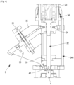
- the hydraulic machine can also be of the type described in the document EP1971776 A1 and on the [ Fig.1 ].
- This hydraulic machine comprises a casing comprising a body and a cover, a separation means capable of performing an alternating movement in the casing between the body and the cover, this separation means defining two chambers.
- the hydraulic machine also comprises hydraulic switching means for supplying liquid to and discharging the aforementioned chambers. These switching means comprise a distribution member capable of taking two stable positions and controlled by the movements of the separation means.
- the body of the casing further contains a compartment connected to a liquid inlet. under pressure and in which the switching means are housed, as well as triggering means comprising a pusher connected to the separation means, capable of causing, at the end of the stroke, a sudden change in the position of the switching means, under the action of an elastic means, for reversing the stroke.
- the distribution member comprises a distribution drawer applied against a flat plate fixed relative to the body of the casing, the distribution drawer being able to slide in a sealed manner, without a seal, against the plate which comprises orifices connected respectively to the chambers of the casing and to a liquid outlet orifice.
- the drawer is then designed to, depending on its position, close certain of the orifices or put them in communication with the fluid inlet or with the exhaust.
- the proportional metering pump comprises a hydraulic machine 1 such as those described above.
- This machine is therefore provided with an inlet 10 and an outlet 11, the hydraulic machine extending along a longitudinal axis x and containing a member 16 capable of performing an alternating movement, the supply of liquid to the pump at the inlet triggering an alternating translational movement along the longitudinal axis x of the member 16.
- the proportional metering pump comprises a volumetric type pump 4, provided with an axis 42, an inlet 40 intended to be placed in fluid communication with a reservoir, and an outlet 41 in fluid communication 51 with the outlet 11 of the hydraulic machine.
- a positive displacement pump is a pump in which a certain quantity of "trapped" fluid is forced to move to the outlet port.
- the flow rate of a positive displacement pump is proportional to the speed of operation of its moving elements and depends very little on the discharge pressure; on the other hand, the energy consumed by the pump is proportional to the pressure difference between the outlet and the inlet of the pump.
- the volumetric pump is a peristaltic pump.
- a peristaltic pump is a pump used to produce a flow of fluids, either liquids or gases.
- the fluid, liquid or gas is contained in a flexible tube, and is driven by a system pressing the tube inside the pump.
- the peristaltic pump generally consists of a head, most often circular in shape, inside which is a flexible tube where the fluid to be pumped progresses.
- This tube is deformed by a rotor equipped with rollers or pebbles, which compress it against the circular head.
- the rollers which block portions of the pipe during their rotation will move the retained fluid in the same direction.
- the suction of the fluid at the pump inlet is possible due to the elasticity of the pipe.
- the proportional metering pump also comprises a motion converter 2 designed to transform the alternating translational motion of the member 16 of the hydraulic machine into a rotational motion.
- This rotational motion is intended to be transmitted to the rotation axis 42 of the volumetric pump 4, preferably peristaltic, so as to drive said pump.
- the motion converter 2 comprises a body 22, a rotor 23 itself housed in another body and provided with at least one helical rail and an actuator 21 which extends longitudinally along the longitudinal axis x of the hydraulic machine.
- the body 22 is fixed relative to the hydraulic machine while the rotor 23 is rotating relative to the hydraulic machine and while the actuator 21 is translating relative to the hydraulic machine.
- the actuator 21 is connected at one of its ends with the member 16 of the hydraulic machine and cooperates with the helical rail of the rotor 23.
- a pinion 24 is further provided, rotationally connected to the rotor 23, which constitutes an output of the converter according to a rotational movement, which is therefore initially induced by the translation of the actuator 21.
- the actuator 21 comprises a shaft 29 connected to the member 16 of the hydraulic machine, a first axis 25 and a second axis 26 each mounted perpendicularly on the shaft 29 of the actuator.
- first axis 25 is provided to slide at a first end 25a in a first straight rail 27a arranged in the body 22 of the motion converter 2 to prevent the shaft 29 from rotating and to thus guide it only in translation.
- the second axis 26 is designed to slide at a first end 26a in a first helical rail 28a arranged on the rotor 23, so as to drive the rotor in rotation, without the shaft 29 rotating.
- the first axis is designed to slide at a first end 25a and at a second end 25b respectively in a first straight rail 27a and in a second straight rail 27b arranged in the body 22 of the motion converter 2.
- the second axis 26 is provided to slide at a first end 26a and at a second end 26b respectively in a first helical rail. 28a and in a second helical rail 28b arranged on the rotor 23, so as to drive the rotor in rotation without the shaft 29 rotating.
- the shaft 29 of the actuator 21 may be provided with one or more longitudinal grooves each capable of accommodating a rib provided on the body 22 of the motion converter 2.
- the shaft 29 is connected to the member 16 of the hydraulic machine by means of a pivot connection 20.
- the member 16 has a natural tendency to rotate on itself during operation.
- the pivot connection allows this movement to be left free, and thus prevents unscrewing of the shaft 29 and/or irregular wear of the member 16.
- the proportional dosing pump includes a variator 3 intended to adjust the speed of rotation from the motion converter 2.
- the variator 3 comprises an output axis 32 substantially parallel to the axis (x) of the hydraulic machine, a toothed cone 30, the axis of revolution of which is inclined such that one of its longitudinal edges extends parallel to the output axis 32.
- a roller 33 is mounted on the output shaft 32 so as to be rotationally integral with the output shaft 32.
- the roller remains in contact with the toothed cone on its longitudinal edge.
- the output pinion 24 of the converter drives the toothed wheel of the cone 30, while the toothed cone 30 drives the roller 33 in rotation by adhesion.
- roller 33 drives the output shaft 32, which itself drives the shaft 42 of the volumetric pump.
- This variator comprises means 34, 340 for adjusting the position of the roller 33 along the output axis 32 of the variator.
- These means comprise a support 340 for fixing the roller, which support is integral with a stuffing box 34 mounted on the body of the rotor 23 and the tightening/loosening of which on the body of the rotor 23 allows the movement of the roller along the output axis 32.
- the variator comprises disengaging means 31 making it possible to move the cone 30 away from the roller 33, so that the cone does not drive plus the pebble by adhesion.
- the toothed wheel of cone 30 remains in contact with the output of the converter (which is preferably pinion 24).
- the disengaging means 31 consist of a pull rod passing through a support 35 secured to the body 22 of the motion converter 2 and anchored in the toothed cone, and of a spring mounted compressed on said pull rod to press the cone against the roller, a pull on said pull rod further compressing the spring and making it possible to move the cone away from the roller.
- the proportional dosing pump comprises an injection T 5 which is consequently supplied by the outlet 11 of the hydraulic machine and by the outlet 41 of the peristaltic pump.
- the injection T is provided with a first non-return valve and a second non-return valve provided respectively downstream of the outlet 11 of the hydraulic machine and downstream of the outlet 41 of the peristaltic pump to prevent the mixture from flowing back towards the hydraulic machine and towards the peristaltic pump respectively.
- an adjustment of the variator 3 is carried out (for example by adjusting the position of the roller on the output shaft 32), according to the expected dosage, before supplying the inlet of the hydraulic machine with main liquid at a predetermined flow rate.
Landscapes
- Engineering & Computer Science (AREA)
- Mechanical Engineering (AREA)
- General Engineering & Computer Science (AREA)
- Reciprocating Pumps (AREA)
- Rotary Pumps (AREA)
- Feeding And Controlling Fuel (AREA)
Claims (14)
- Eine Pumpe zur proportionalen Dosierung, beinhaltend eine hydraulische Maschine (1), die über einen Eingang (10) und einen Ausgang (11) verfügt, wobei sich die hydraulische Maschine entlang einer Längsachse (x) erstreckt und ein Bauteil (16) einschließt, das dazu fähig ist, eine hin- und hergehende Bewegung entlang dieser Achse auszuführen, wobei die Versorgung der hydraulischen Maschine mit einer Hauptflüssigkeit am Eingang eine translatorische hin- und hergehende Bewegung des Bauteils (16) entlang der Längsachse (x) auslöst, wobei die Pumpe zur proportionalen Dosierung Folgendes umfasst:- eine Verdrängerpumpe (4), die über eine Drehachse (42), einen Eingang (40), der dazu bestimmt ist, mit einem Zusatzstofftank in Fluidkommunikation gebracht zu werden, und einen Ausgang (41) in Fluidkommunikation (51) mit dem Ausgang (11) der hydraulischen Maschine verfügt,- einen Bewegungsumwandler (2), der dafür vorgesehen ist, die translatorische hin- und hergehende Bewegung des Bauteils (16) der hydraulischen Maschine in eine Drehbewegung zu transformieren, wobei die Drehbewegung direkt oder indirekt auf die Drehachse der Verdrängerpumpe (4) übertragen wird,sodass die Versorgung der hydraulischen Maschine die Verdrängerpumpe betätigt, die auf diese Weise den Ausgang (11) der hydraulischen Maschine mit Zusatzstoff versorgt, wobei sich der Zusatzstoff am Ausgang der hydraulischen Maschine mit der Hauptflüssigkeit mischt.
- Pumpe zur proportionalen Dosierung gemäß Anspruch 1, wobei die Verdrängerpumpe (4) eine Peristaltikpumpe ist.
- Pumpe zur proportionalen Dosierung gemäß Anspruch 1 oder 2, wobei die Pumpe zur proportionalen Dosierung ferner einen Variator (3) umfasst, der dafür vorgesehen ist, die Geschwindigkeit der von dem Bewegungsumwandler (2) kommenden Drehung anzupassen.
- Pumpe zur proportionalen Dosierung gemäß einem der vorhergehenden Ansprüche, wobei der Bewegungsumwandler (2) Folgendes umfasst: einen Rotor (23), der über mindestens eine schraubenförmige Schiene (28a, 28b) verfügt, und ein Betätigungselement (21), die sich jeweils längs entlang der Längsachse (x) der hydraulischen Maschine erstrecken, wobei das Betätigungselement an einem seiner Enden mit dem Bauteil (16) der hydraulischen Maschine verbunden ist und mit der schraubenförmigen Schiene des Rotors (23) zusammenwirkt, sowie einen Ausgang, der mit dem Rotor (23) drehfest verbunden ist und vorzugsweise die Form eines Ritzels (24) aufweist, wobei der Aufwärtshub und der darauffolgende Abwärtshub des Bauteils (16) der hydraulischen Maschine die Drehung des Rotors (23) in einer gleichen Richtung bewirken.
- Pumpe zur proportionalen Dosierung gemäß dem vorhergehenden Anspruch, wobei das Betätigungselement (21) eine Welle (29), die mit dem Bauteil (16) der hydraulischen Maschine verbunden ist, eine erste Achse (25) und eine zweite Achse (26), die senkrecht auf der Welle (29) des Betätigungselements angebracht sind, beinhaltet, wobei die erste Achse dafür vorgesehen ist, an einem ersten Ende (25a, 25b) in einer ersten geradlinigen Schiene (27a, 27b), die in dem Körper (22) des Bewegungsumwandlers (2) eingerichtet ist, zu gleiten, während die zweite Achse dafür vorgesehen ist, an einem ersten Ende (26a, 26b) in der schraubenförmigen Schiene (28a, 28b), die an dem Rotor (23) eingerichtet ist, zu gleiten.
- Pumpe zur proportionalen Dosierung gemäß Anspruch 4, wobei das Betätigungselement (21) eine Welle (29), die mit dem Bauteil (16) verbunden ist, eine erste Achse (25) und eine zweite Achse (26), die senkrecht auf der Welle (29) des Betätigungselements angebracht sind, beinhaltet, wobei die erste Achse dafür vorgesehen ist, an einem ersten Ende und an einem zweiten Ende (25a, 25b) jeweils in einer ersten geradlinigen Schiene bzw. in einer zweiten geradlinigen Schiene (27a, 27b), die in dem Körper (22) des Bewegungsumwandlers (2) eingerichtet sind, zu gleiten, während die zweite Achse dafür vorgesehen ist, an einem ersten Ende und an einem zweiten Ende (26a, 26b) jeweils in einer ersten schraubenförmigen Schiene bzw. in einer zweiten schraubenförmigen Schiene (28a, 28b), die an dem Rotor (23) eingerichtet sind, zu gleiten.
- Pumpe zur proportionalen Dosierung gemäß einem der Ansprüche 5 oder 6, wobei die Welle (29) mittels einer Gelenkverbindung (20) mit dem Bauteil (16) der hydraulischen Maschine verbunden ist.
- Pumpe zur proportionalen Dosierung gemäß einem der Ansprüche 3 bis 7, wobei der Variator (3) eine Ausgangsachse (32), einen Zahnkegel (30), dessen Rotationsachse in Bezug auf die Ausgangsachse (32) geneigt ist, sodass sich eine seiner Profilkanten parallel zu der Ausgangsachse (32) erstreckt, eine Rolle (33), die mit der Ausgangsachse (32) drehfest verbunden ist und dazu in der Lage ist, sich entlang der Ausgangsachse (32) zu verschieben, beinhaltet, wobei das Ausgangsritzel (24) des Umwandlers in das Zahnrad des Kegels (30) eingreift, wobei der Zahnkegel (30) die Rolle (33) kraftschlüssig drehantreibt, ebenso wie die Ausgangsachse (32), die wiederum die Achse (42) der Verdrängerpumpe antreibt.
- Pumpe zur proportionalen Dosierung gemäß dem vorhergehenden Anspruch, wobei der Variator (3) Mittel (34, 340) zum Einstellen der Position der Rolle (33) auf der Ausgangsachse (32) des Variators beinhaltet, wobei diese Mittel eine Halterung zur Befestigung (340) der Rolle umfassen, die ferner mit einer Stopfbuchse (34) fest verbunden ist, welche an dem Körper des Rotors angebracht ist und deren Anziehen/Lösen am Körper des Rotors (23) die Verschiebung der Rolle entlang der Ausgangsachse (32) des Variators gestattet.
- Pumpe zur proportionalen Dosierung gemäß Anspruch 8 oder 9, wobei der Variator Ausrückmittel (31) umfasst, die es gestatten, die Oberfläche des Kegels (30) von der Rolle (33) zu entfernen, um das kraftschlüssige Antreiben der Rolle zu unterbinden.
- Pumpe zur proportionalen Dosierung gemäß dem vorhergehenden Anspruch, wobei die Ausrückmittel (31) aus einem Zugelement, das durch eine Halterung (35), die mit dem Körper (22) des Bewegungsumwandlers (2) fest verbunden ist, hindurchgeht und in dem Zahnkegel verankert ist, und einer Feder, die zusammengedrückt auf dem Zugelement angebracht, um den Kegel gegen die Rolle zu drücken, bestehen, wobei ein Zug an dem Zugelement die Feder noch weiter zusammendrückt und es gestattet, den Kegel von der Rolle zu entfernen.
- Pumpe zur proportionalen Dosierung gemäß einem der vorhergehenden Ansprüche, wobei die Pumpe zur proportionalen Dosierung einen T-Anschluss (5) umfasst, der von dem Ausgang (11) der hydraulischen Maschine und von dem Ausgang (41) der Verdrängerpumpe versorgt wird.
- Pumpe zur proportionalen Dosierung gemäß dem vorhergehenden Anspruch, wobei der T-Anschluss über ein erstes Rückschlagventil und über ein zweites Rückschlagventil verfügt, die jeweils dafür vorgesehen sind, den Rückfluss zu der hydraulischen Maschine bzw. zu der Verdrängerpumpe zu verhindern.
- Ein Verfahren zur proportionalen Dosierung unter Verwendung einer Pumpe zur proportionalen Dosierung gemäß einem der Ansprüche 3 bis 13, wobei das Verfahren die folgenden Schritte beinhaltet:- Anschließen des Eingangs (40) der Verdrängerpumpe (4) an einen Behälter, der mit dem zu dosierenden Zusatzstoff gefüllt ist,- Anschließen des Eingangs (10) der hydraulischen Maschine (1) an eine Hauptflüssigkeitsquelle,- Einstellen des Variators (3), der dafür vorgesehen ist, die Geschwindigkeit der aus dem Bewegungsumwandler (2) resultierenden Drehung in Abhängigkeit von der erwarteten Dosierung anzupassen,- Versorgen des Eingangs der hydraulischen Maschine mit Hauptflüssigkeit gemäß einem vorbestimmten Durchfluss, sodass die Versorgung der hydraulischen Maschine die Verdrängerpumpe betätigt, die auf diese Weise den Ausgang (11) der hydraulischen Maschine oder aber einen T-Anschluss, der von dem Ausgang (11) der hydraulischen Maschine und von dem Ausgang (41) der Verdrängerpumpe versorgt wird, wenn der Ausgang der Pumpe über einen T-Anschluss verfügt, mit Zusatzstoff versorgt, wobei sich der Zusatzstoff mit der Hauptflüssigkeit mischt.
Applications Claiming Priority (2)
| Application Number | Priority Date | Filing Date | Title |
|---|---|---|---|
| FR2102019A FR3120402B1 (fr) | 2021-03-02 | 2021-03-02 | Procede et pompe de dosage proportionnel a faible debit |
| PCT/EP2022/054788 WO2022184576A1 (fr) | 2021-03-02 | 2022-02-25 | Procede et pompe de dosage proportionnel a faible debit |
Publications (3)
| Publication Number | Publication Date |
|---|---|
| EP4301981A1 EP4301981A1 (de) | 2024-01-10 |
| EP4301981C0 EP4301981C0 (de) | 2024-12-11 |
| EP4301981B1 true EP4301981B1 (de) | 2024-12-11 |
Family
ID=77180058
Family Applications (1)
| Application Number | Title | Priority Date | Filing Date |
|---|---|---|---|
| EP22709673.2A Active EP4301981B1 (de) | 2021-03-02 | 2022-02-25 | Verfahren und pumpe zur proportionalen dosierung mit geringem durchfluss |
Country Status (10)
| Country | Link |
|---|---|
| US (1) | US12510063B2 (de) |
| EP (1) | EP4301981B1 (de) |
| JP (1) | JP7774069B2 (de) |
| CN (1) | CN116917619A (de) |
| CA (1) | CA3209186A1 (de) |
| ES (1) | ES3007983T3 (de) |
| FR (1) | FR3120402B1 (de) |
| IL (1) | IL305387A (de) |
| PL (1) | PL4301981T3 (de) |
| WO (1) | WO2022184576A1 (de) |
Family Cites Families (21)
| Publication number | Priority date | Publication date | Assignee | Title |
|---|---|---|---|---|
| US2274097A (en) * | 1938-10-27 | 1942-02-24 | John B Sheerer | Crankless engine |
| US3053842A (en) * | 1957-02-08 | 1962-09-11 | Firm Josef Meissner | Mixing method |
| DE2213298A1 (de) * | 1972-03-18 | 1973-09-27 | Rww Filter Gmbh | Dosiergeraet |
| DE2855085C2 (de) * | 1978-08-18 | 1986-04-24 | S.R.M. Hydromekanik Ab, Stockholm | Pumpenanordnung zur Versorgung von Verbrauchern mit stark schwankendem Bedarf an Druckflüssigkeit |
| JPS59188900U (ja) * | 1983-06-01 | 1984-12-14 | 株式会社 喜多村合金製作所 | 助燃剤の定量供給混合装置 |
| FR2602282B1 (fr) | 1986-07-31 | 1988-09-23 | Cloup Jean | Perfectionnement aux dispositifs d'injection d'un produit additif dose dans un fluide principal |
| FR2681646B1 (fr) * | 1991-09-19 | 1995-05-19 | Ody Ste Civile Rech | Pompe comportant un systeme de dosage, et dispositif comportant une telle pompe, pour injection dans un liquide principal d'un additif. |
| JPH062566A (ja) * | 1992-06-15 | 1994-01-11 | T I Ii:Kk | 動力伝達装置 |
| US5234322A (en) * | 1992-12-24 | 1993-08-10 | Chemilizer Products, Inc. | Proportioning pump improvements |
| US5951265A (en) * | 1997-12-29 | 1999-09-14 | Diemold International, Inc. | Fluid driven reciprocating engine or pump having overcenter, snap-action mechanical valve control |
| FR2789445B1 (fr) | 1999-02-09 | 2001-03-23 | Dosatron Internat Sa | Machine hydraulique differentielle a mouvement alternatif, en particulier moteur hydraulique differentiel |
| US8303277B2 (en) * | 2002-11-21 | 2012-11-06 | International Dispensing Corporation | Blending pump assembly |
| FR2896279B1 (fr) | 2006-01-13 | 2008-02-29 | Dosatron International | Machine hydraulique, en particulier moteur hydraulique, et doseur comportant un tel moteur. |
| DE102008019783A1 (de) * | 2007-04-23 | 2008-11-13 | Troska, Günter | Verdrängerdosierpumpe |
| FR2967218B1 (fr) * | 2010-11-08 | 2016-09-02 | Dosatron International | Doseur proportionnel d'un liquide auxiliaire dans un liquide principal. |
| EP3040226B1 (de) * | 2014-12-30 | 2020-07-08 | Dana Belgium N.V. | Hydraulischer Hybridantriebsstrang |
| FR3049992B1 (fr) | 2016-04-07 | 2018-04-20 | Dosatron International | Pompe a dosage proportionnel, procede de montage et de demontage d'une telle pompe |
| WO2018042354A1 (en) * | 2016-09-02 | 2018-03-08 | Stackpole International Engineered Products, Ltd. | Dual input pump and system |
| US10371137B2 (en) * | 2016-09-06 | 2019-08-06 | Hamilton Sundstrand Corporation | Metering for fluid motor and pump combination |
| US10480547B2 (en) * | 2017-11-30 | 2019-11-19 | Umbra Cuscinetti, Incorporated | Electro-mechanical actuation system for a piston-driven fluid pump |
| US11035348B2 (en) * | 2018-08-28 | 2021-06-15 | National Oilwell Varco, L.P. | Reciprocating pumps having a pivoting arm |
-
2021
- 2021-03-02 FR FR2102019A patent/FR3120402B1/fr active Active
-
2022
- 2022-02-25 IL IL305387A patent/IL305387A/en unknown
- 2022-02-25 PL PL22709673.2T patent/PL4301981T3/pl unknown
- 2022-02-25 JP JP2023553118A patent/JP7774069B2/ja active Active
- 2022-02-25 EP EP22709673.2A patent/EP4301981B1/de active Active
- 2022-02-25 ES ES22709673T patent/ES3007983T3/es active Active
- 2022-02-25 CN CN202280018749.1A patent/CN116917619A/zh active Pending
- 2022-02-25 CA CA3209186A patent/CA3209186A1/fr active Pending
- 2022-02-25 WO PCT/EP2022/054788 patent/WO2022184576A1/fr not_active Ceased
- 2022-02-25 US US18/548,688 patent/US12510063B2/en active Active
Also Published As
| Publication number | Publication date |
|---|---|
| EP4301981A1 (de) | 2024-01-10 |
| FR3120402B1 (fr) | 2023-04-14 |
| JP2024512896A (ja) | 2024-03-21 |
| EP4301981C0 (de) | 2024-12-11 |
| IL305387A (en) | 2023-10-01 |
| WO2022184576A1 (fr) | 2022-09-09 |
| US20240309864A1 (en) | 2024-09-19 |
| JP7774069B2 (ja) | 2025-11-20 |
| CN116917619A (zh) | 2023-10-20 |
| CA3209186A1 (fr) | 2022-09-09 |
| FR3120402A1 (fr) | 2022-09-09 |
| ES3007983T3 (en) | 2025-03-21 |
| PL4301981T3 (pl) | 2025-04-22 |
| US12510063B2 (en) | 2025-12-30 |
Similar Documents
| Publication | Publication Date | Title |
|---|---|---|
| FR2967218A1 (fr) | Doseur proportionnel d'un liquide auxiliaire dans un liquide principal. | |
| EP1971776B1 (de) | Hydraulische maschine, insbesondere hydraulikmotor, und solch einen motor umfassende dosiervorrichtung | |
| EP4301981B1 (de) | Verfahren und pumpe zur proportionalen dosierung mit geringem durchfluss | |
| EP3485165B1 (de) | Dosierungsmechanismus für eine dosierpumpe sowie zugehöriges pump- und verwendungsverfahren | |
| EP0400496B1 (de) | Volumetrische Pumpe und Verfahren zum volumetrischen Pumpen | |
| FR2801955A1 (fr) | Soupape de contre-pression a aeration automatique | |
| EP3362685B1 (de) | Hydraulische maschine und mit solch einer maschine ausgestattete reversible dosierpumpe | |
| FR3154771A1 (fr) | Pompe a dosage proportionnel et procede de dosage associe | |
| FR2566052A1 (fr) | Pompe a refoulement continu | |
| FR3156172A1 (fr) | Pompe a dosage proportionnel | |
| FR2527700A1 (fr) | Pompe doseuse a membrane, pourvue de deux soupapes de retenue | |
| EP0172076A1 (de) | Abmess-Dosiereinrichtung für Fluide | |
| FR2604146A1 (fr) | Doseur volumetrique | |
| FR2602220A1 (fr) | Sas extracteur doseur de matieres granuleuses ou pulverulentes | |
| WO2003035476A1 (fr) | Systeme d'injection d'au moins deux produits dans des recipients | |
| EP1872096A1 (de) | Zählereinrichtung mit drehtrommel | |
| FR2667676A1 (fr) | Pompe a huile pour moteur a combustion interne. | |
| FR2789735A1 (fr) | Pompe doseuse volumetrique | |
| FR2574493A1 (fr) | Pompe de puisage | |
| FR2938643A1 (fr) | Procede de dosage volumetrique d'un fluide au moyen d'un piston et dispositif destine a ce procede | |
| BE388521A (de) |
Legal Events
| Date | Code | Title | Description |
|---|---|---|---|
| STAA | Information on the status of an ep patent application or granted ep patent |
Free format text: STATUS: UNKNOWN |
|
| STAA | Information on the status of an ep patent application or granted ep patent |
Free format text: STATUS: THE INTERNATIONAL PUBLICATION HAS BEEN MADE |
|
| PUAI | Public reference made under article 153(3) epc to a published international application that has entered the european phase |
Free format text: ORIGINAL CODE: 0009012 |
|
| STAA | Information on the status of an ep patent application or granted ep patent |
Free format text: STATUS: REQUEST FOR EXAMINATION WAS MADE |
|
| 17P | Request for examination filed |
Effective date: 20230929 |
|
| AK | Designated contracting states |
Kind code of ref document: A1 Designated state(s): AL AT BE BG CH CY CZ DE DK EE ES FI FR GB GR HR HU IE IS IT LI LT LU LV MC MK MT NL NO PL PT RO RS SE SI SK SM TR |
|
| DAV | Request for validation of the european patent (deleted) | ||
| DAX | Request for extension of the european patent (deleted) | ||
| GRAP | Despatch of communication of intention to grant a patent |
Free format text: ORIGINAL CODE: EPIDOSNIGR1 |
|
| STAA | Information on the status of an ep patent application or granted ep patent |
Free format text: STATUS: GRANT OF PATENT IS INTENDED |
|
| INTG | Intention to grant announced |
Effective date: 20240705 |
|
| GRAS | Grant fee paid |
Free format text: ORIGINAL CODE: EPIDOSNIGR3 |
|
| GRAA | (expected) grant |
Free format text: ORIGINAL CODE: 0009210 |
|
| STAA | Information on the status of an ep patent application or granted ep patent |
Free format text: STATUS: THE PATENT HAS BEEN GRANTED |
|
| AK | Designated contracting states |
Kind code of ref document: B1 Designated state(s): AL AT BE BG CH CY CZ DE DK EE ES FI FR GB GR HR HU IE IS IT LI LT LU LV MC MK MT NL NO PL PT RO RS SE SI SK SM TR |
|
| REG | Reference to a national code |
Ref country code: GB Ref legal event code: FG4D Free format text: NOT ENGLISH |
|
| REG | Reference to a national code |
Ref country code: CH Ref legal event code: EP |
|
| REG | Reference to a national code |
Ref country code: DE Ref legal event code: R096 Ref document number: 602022008627 Country of ref document: DE |
|
| REG | Reference to a national code |
Ref country code: IE Ref legal event code: FG4D Free format text: LANGUAGE OF EP DOCUMENT: FRENCH |
|
| U01 | Request for unitary effect filed |
Effective date: 20250109 |
|
| U07 | Unitary effect registered |
Designated state(s): AT BE BG DE DK EE FI FR IT LT LU LV MT NL PT RO SE SI Effective date: 20250218 |
|
| REG | Reference to a national code |
Ref country code: ES Ref legal event code: FG2A Ref document number: 3007983 Country of ref document: ES Kind code of ref document: T3 Effective date: 20250321 |
|
| U20 | Renewal fee for the european patent with unitary effect paid |
Year of fee payment: 4 Effective date: 20250226 |
|
| PG25 | Lapsed in a contracting state [announced via postgrant information from national office to epo] |
Ref country code: HR Free format text: LAPSE BECAUSE OF FAILURE TO SUBMIT A TRANSLATION OF THE DESCRIPTION OR TO PAY THE FEE WITHIN THE PRESCRIBED TIME-LIMIT Effective date: 20241211 |
|
| PG25 | Lapsed in a contracting state [announced via postgrant information from national office to epo] |
Ref country code: NO Free format text: LAPSE BECAUSE OF FAILURE TO SUBMIT A TRANSLATION OF THE DESCRIPTION OR TO PAY THE FEE WITHIN THE PRESCRIBED TIME-LIMIT Effective date: 20250311 |
|
| PG25 | Lapsed in a contracting state [announced via postgrant information from national office to epo] |
Ref country code: GR Free format text: LAPSE BECAUSE OF FAILURE TO SUBMIT A TRANSLATION OF THE DESCRIPTION OR TO PAY THE FEE WITHIN THE PRESCRIBED TIME-LIMIT Effective date: 20250312 |
|
| PG25 | Lapsed in a contracting state [announced via postgrant information from national office to epo] |
Ref country code: RS Free format text: LAPSE BECAUSE OF FAILURE TO SUBMIT A TRANSLATION OF THE DESCRIPTION OR TO PAY THE FEE WITHIN THE PRESCRIBED TIME-LIMIT Effective date: 20250311 |
|
| PG25 | Lapsed in a contracting state [announced via postgrant information from national office to epo] |
Ref country code: SM Free format text: LAPSE BECAUSE OF FAILURE TO SUBMIT A TRANSLATION OF THE DESCRIPTION OR TO PAY THE FEE WITHIN THE PRESCRIBED TIME-LIMIT Effective date: 20241211 |
|
| PGFP | Annual fee paid to national office [announced via postgrant information from national office to epo] |
Ref country code: PL Payment date: 20250131 Year of fee payment: 4 |
|
| PG25 | Lapsed in a contracting state [announced via postgrant information from national office to epo] |
Ref country code: IS Free format text: LAPSE BECAUSE OF FAILURE TO SUBMIT A TRANSLATION OF THE DESCRIPTION OR TO PAY THE FEE WITHIN THE PRESCRIBED TIME-LIMIT Effective date: 20250411 |
|
| PG25 | Lapsed in a contracting state [announced via postgrant information from national office to epo] |
Ref country code: SK Free format text: LAPSE BECAUSE OF FAILURE TO SUBMIT A TRANSLATION OF THE DESCRIPTION OR TO PAY THE FEE WITHIN THE PRESCRIBED TIME-LIMIT Effective date: 20241211 |
|
| PG25 | Lapsed in a contracting state [announced via postgrant information from national office to epo] |
Ref country code: CZ Free format text: LAPSE BECAUSE OF FAILURE TO SUBMIT A TRANSLATION OF THE DESCRIPTION OR TO PAY THE FEE WITHIN THE PRESCRIBED TIME-LIMIT Effective date: 20241211 |
|
| PG25 | Lapsed in a contracting state [announced via postgrant information from national office to epo] |
Ref country code: MC Free format text: LAPSE BECAUSE OF FAILURE TO SUBMIT A TRANSLATION OF THE DESCRIPTION OR TO PAY THE FEE WITHIN THE PRESCRIBED TIME-LIMIT Effective date: 20241211 |
|
| REG | Reference to a national code |
Ref country code: CH Ref legal event code: PL |
|
| PLBE | No opposition filed within time limit |
Free format text: ORIGINAL CODE: 0009261 |
|
| STAA | Information on the status of an ep patent application or granted ep patent |
Free format text: STATUS: NO OPPOSITION FILED WITHIN TIME LIMIT |
|
| PG25 | Lapsed in a contracting state [announced via postgrant information from national office to epo] |
Ref country code: CH Free format text: LAPSE BECAUSE OF NON-PAYMENT OF DUE FEES Effective date: 20250228 |
|
| 26N | No opposition filed |
Effective date: 20250912 |
|
| PG25 | Lapsed in a contracting state [announced via postgrant information from national office to epo] |
Ref country code: IE Free format text: LAPSE BECAUSE OF NON-PAYMENT OF DUE FEES Effective date: 20250225 |
|
| U20 | Renewal fee for the european patent with unitary effect paid |
Year of fee payment: 5 Effective date: 20260226 |
|
| PGFP | Annual fee paid to national office [announced via postgrant information from national office to epo] |
Ref country code: GB Payment date: 20260225 Year of fee payment: 5 |
|
| PGFP | Annual fee paid to national office [announced via postgrant information from national office to epo] |
Ref country code: ES Payment date: 20260310 Year of fee payment: 5 |
|
| PGFP | Annual fee paid to national office [announced via postgrant information from national office to epo] |
Ref country code: TR Payment date: 20260206 Year of fee payment: 5 |