EP4306744A2 - Vibreur pour béton - Google Patents
Vibreur pour béton Download PDFInfo
- Publication number
- EP4306744A2 EP4306744A2 EP23183006.8A EP23183006A EP4306744A2 EP 4306744 A2 EP4306744 A2 EP 4306744A2 EP 23183006 A EP23183006 A EP 23183006A EP 4306744 A2 EP4306744 A2 EP 4306744A2
- Authority
- EP
- European Patent Office
- Prior art keywords
- housing
- vibrator
- coupled
- concrete vibrator
- motor
- Prior art date
- Legal status (The legal status is an assumption and is not a legal conclusion. Google has not performed a legal analysis and makes no representation as to the accuracy of the status listed.)
- Pending
Links
- 239000012530 fluid Substances 0.000 claims description 11
- 238000004891 communication Methods 0.000 description 13
- 238000003780 insertion Methods 0.000 description 8
- 230000037431 insertion Effects 0.000 description 8
- 238000005286 illumination Methods 0.000 description 4
- 238000000034 method Methods 0.000 description 4
- 238000010276 construction Methods 0.000 description 2
- 230000008878 coupling Effects 0.000 description 2
- 238000010168 coupling process Methods 0.000 description 2
- 238000005859 coupling reaction Methods 0.000 description 2
- 230000000881 depressing effect Effects 0.000 description 2
- 230000009286 beneficial effect Effects 0.000 description 1
- 230000010267 cellular communication Effects 0.000 description 1
- 238000002485 combustion reaction Methods 0.000 description 1
- 239000012141 concentrate Substances 0.000 description 1
- 230000000994 depressogenic effect Effects 0.000 description 1
- 230000009977 dual effect Effects 0.000 description 1
- 230000001939 inductive effect Effects 0.000 description 1
- 230000008595 infiltration Effects 0.000 description 1
- 238000001764 infiltration Methods 0.000 description 1
- 230000002093 peripheral effect Effects 0.000 description 1
- 230000000704 physical effect Effects 0.000 description 1
- 230000002265 prevention Effects 0.000 description 1
- 230000002459 sustained effect Effects 0.000 description 1
- 238000012559 user support system Methods 0.000 description 1
Images


Classifications
-
- E—FIXED CONSTRUCTIONS
- E04—BUILDING
- E04G—SCAFFOLDING; FORMS; SHUTTERING; BUILDING IMPLEMENTS OR AIDS, OR THEIR USE; HANDLING BUILDING MATERIALS ON THE SITE; REPAIRING, BREAKING-UP OR OTHER WORK ON EXISTING BUILDINGS
- E04G21/00—Preparing, conveying, or working-up building materials or building elements in situ; Other devices or measures for constructional work
- E04G21/02—Conveying or working-up concrete or similar masses able to be heaped or cast
- E04G21/06—Solidifying concrete, e.g. by application of vacuum before hardening
- E04G21/08—Internal vibrators, e.g. needle vibrators
-
- B—PERFORMING OPERATIONS; TRANSPORTING
- B25—HAND TOOLS; PORTABLE POWER-DRIVEN TOOLS; MANIPULATORS
- B25F—COMBINATION OR MULTI-PURPOSE TOOLS NOT OTHERWISE PROVIDED FOR; DETAILS OR COMPONENTS OF PORTABLE POWER-DRIVEN TOOLS NOT PARTICULARLY RELATED TO THE OPERATIONS PERFORMED AND NOT OTHERWISE PROVIDED FOR
- B25F5/00—Details or components of portable power-driven tools not particularly related to the operations performed and not otherwise provided for
- B25F5/02—Construction of casings, bodies or handles
Definitions
- the present invention relates to power tools, and more particularly to concrete vibrators.
- Concrete vibrators are typically used to spread poured concrete around a framework, such as rebar, in a construction operation. Such concrete vibrators are typically powered by an internal combustion engine, which can be difficult to carry by an operator using the concrete vibrator while on a worksite.
- the invention provides, in one aspect, a concrete vibrator including a housing, a strap, an electric motor, a flexible saft, a vibrator head, and a battery pack.
- the strap is coupled to the housing.
- the electric motor is coupled to the housing.
- the flexible shaft has a first end coupled to the motor and an opposite, second end.
- the vibrator head is coupled to the second end of the shaft.
- the vibrator head is configured to receive torque from the motor to cause the vibrator head to vibrate.
- the battery pack is coupled to a battery receptacle defined on the housing.
- the battery pack is configured to provide electric current to the electric motor to drive the motor and the shaft.
- the concrete vibrator is operable in a messenger bag configuration in which the strap is used to carry the concrete vibrator with the housing in a horizontal orientation.
- the invention provides, in another independent aspect, a concrete vibrator including a housing, an electric motor, a flexible shaft, a vibrator head, a battery pack, and a tether.
- the housing has a front surface, an opposite rear surface, and a plurality of side surfaces spanning the front surface and the rear surface.
- the electric motor is coupled to the housing.
- the flexible shaft has a first end coupled to the motor and projecting from the front surface of the housing.
- the flexible shaft has an opposite second end.
- the vibrator head is coupled to the second end of the shaft and is configured to receive torque from the motor and the shaft to cause the vibrator head to vibrate.
- the battery pack is coupled to a battery receptacle defined on the housing.
- the battery pack is configured to provide electric current to the electric motor to drive the motor and the shaft.
- the tether is coupled to the housing and is configured to be engaged by an external structure.
- the invention provides, in another independent aspect, a concrete vibrator including a housing, an electric motor, a flexible shaft, a vibrator head, a battery pack, and at least one means.
- the housing defines an interior volume.
- the electric motor is coupled to the housing.
- the flexible shaft has a first end coupled to the motor and project from the housing.
- the flexible shaft has an opposite, second end.
- the vibrator head is coupled to the second end of the shaft.
- the vibrator head is configured to receive torque from the motor and the shaft to cause the vibrator head to vibrate.
- the battery pack is coupled to a battery receptacle defined on the housing.
- the battery pack is configured to provide electric current to the electric motor to drive the motor and the shaft.
- the at least one means prevents ingress of matter into the interior volume of the housing.
- the invention provides, in another independent aspect, a concrete vibrator comprising:
- the concrete vibrator may further comprise a handle extending from the housing.
- the handle may include a first end having a first attachment feature and a second end having a second attachment feature, the strap having a first strap end configured to be coupled to the first attachment feature and a second strap end configured to be coupled to the second attachment feature.
- the first end of the handle may be bifurcated at the first end to define a first arm and a second arm spaced from the first arm, and the first attachment feature may be a post extending between the first arm and the second arm.
- the concrete vibrator may further comprise a handle extending from the housing, wherein the concrete vibrator may be operable in a briefcase configuration in which the housing is supportable in the horizontal orientation with the handle providing the support for the concrete vibrator.
- the housing may include a front surface from which the first end of the flexible shaft protrudes, an opposite rear surface, and a plurality of side surfaces spanning the front surface and the rear surface.
- the concrete vibrator may further comprise a handle extending from one of the side surfaces.
- the strap may be configured to be coupled to one of the side surfaces.
- the invention provides, in another independent aspect, a concrete vibrator comprising:
- the housing may have a stepped surface positioned between the front surface and the rear surface thereof, the tether being coupled to the stepped surface.
- the concrete vibrator may further comprise a shroud surrounding the first end of the flexible shaft and coupled to the housing.
- the tether may be coupled to the shroud.
- the tether may include a tether mount removably coupled to the housing by a fastener and a tether ring which may be secured to the housing by the tether plate.
- the tether mount may be removably coupled to a shroud which surrounds the first end of the flexible shaft and may be coupled to the housing.
- the invention provides, in another independent aspect, a concrete vibrator comprising:
- the means may be a battery latch cover which may be movable between a protection position in which ingress of matter into the interior volume of the housing is prevented by the battery latch cover and a battery engaging position in which the battery may engage the battery receptacle, and the battery and the battery latch cover together may prevent ingress of matter into the interior volume.
- the concrete vibrator may further comprise a spring configured to bias the battery latch cover to the protection position.
- the housing may include a fastener recess on an outer profile thereof, the fastener recess being configured to receive a fastener, and the means may be a plug engaged with the fastener recess to prevent ingress of debris or fluid into the fastener recess and thus the interior of the housing via the fastener recess.
- the concrete vibrator may further comprise a switch configured to control operation of the electric motor, wherein the means may be a switch cover surrounding the switch.
- the switch cover may be deformable to permit operation of the switch while the switch cover surrounds the switch.
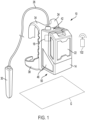
- FIGS. 1 and 2 illustrate a concrete vibrator 10 including a housing 14, a power unit (e.g., a brushless direct current electric motor 18) positioned within the housing 14, and a battery pack 22 carried onboard the housing 14 for providing power to the electric motor 18.
- the battery pack 22 and the motor 18 can be configured as an 80 Volt high power battery pack and motor, such as the 80 Volt battery pack and motor disclosed in U.S. Patent Application No. 16/025,491 filed on July 2, 2018 (now U.S. Patent Application Publication No. 2019/0006980 ), the entirety of which is incorporated herein by reference.
- the battery cells within the battery pack 22 have a nominal voltage of up to about 80 V.
- the battery cells are operable to output a sustained operating discharge current of between about 40 A and about 60 A. In some embodiments, each of the battery cells has a capacity of between about 3.0 Ah and about 5.0 Ah. And, in some embodiments of the motor 18 when used with the 80 Volt battery pack 22, the motor 18 has a power output of at least about 2760 W and a nominal outer diameter (measured at the stator) of up to about 80 mm.
- the concrete vibrator 10 also includes a flexible shaft 26 extending from the housing 14 and a vibrator head 30 connected to an end of the shaft 26. As explained in further detail below, the shaft 26 receives torque from the motor 18. The torque is transmitted to the vibrating head 30, causing it to vibrate.
- the concrete vibrator 10 also includes a pair of straps 34 that permit the concrete vibrator 10 to be carried in a "backpack configuration" in which the housing 14 is vertically oriented (i.e., with the length dimension of the housing 14 extending parallel with the height dimension of the user).
- the concrete vibrator 10 may optionally include a hip band 38 in addition to the straps 34 to further secure the concrete vibrator 10 to the user.
- the flexible shaft 26 extends from a top surface 42 of the housing 14. In this manner, the flexible shaft 26 extends from the housing 14 in a direction away from the ground G when the concrete vibrator 10 is being carried in the backpack configuration.
- the straps 34 wrap around the user's shoulders and the hip band 38 wraps around the user's hips or waist.
- a user can easily maneuver the flexible shaft 26 and vibrating head 30 with a single hand while supporting the vibrator 10 with their body and through the straps 34.
- the user may carry the vibrating head 30 with either their right hand or left hand without requiring the shaft 26 to cross sideways in front or in back of the user, as it would if the shaft 26 were to extend from one of the side-facing surfaces 46 of the housing 14 when the vibrator 10 is carried in the backpack configuration.
- the shaft 26 extends upward from the top surface 42 of the housing 14, is bent into a "U" shape, and redirected downward for the vibrating head 30 to be grasped by the user.
- the flexible shaft 26 may protrude from a downward-inclined surface (embodiment of FIGS. 7-9 ) of the housing 14 adjacent the top surface 42, such that the shaft 26 may extend from the housing 14 and downward towards the ground G, without requiring the shaft 26 to be initially bent into a "U" shape, when the user carries the vibrator 10 in the backpack configuration.
- the flexible shaft 26 may extend from a bottom surface 50 of the housing 14 when the vibrator 10 is carried in the backpack configuration.
- the flexible shaft 26 protrudes from the bottom surface 50 of the housing 14 in a direction towards the ground when a user supports the vibrator with the straps 34.
- the vibrating head 30 may be held with either the user's left or right hand without the flexible shaft 26 crossing sideways in front or in back of the user. If the shaft 26 were to extend from one of the side-facing surfaces of the housing 14 when the vibrator 10 is carried in the backpack configuration, the shaft 26 would cross sideways in front or in back of the user.
- the concrete vibrator 10 includes a handle 54 extending from one of the side-facing surfaces 46 of the housing 14 extending between the top and bottom surfaces 42, 50 of the housing 14.
- the handle 54 permits the concrete vibrator 10 to be alternatively carried in a "briefcase configuration" in which the housing 14 is horizontally oriented (i.e., with the length dimension of the housing 14 extending perpendicular to the height dimension of the user).
- the flexible shaft 26 protrudes from the housing 14 in a direction that is substantially parallel with the ground G, allowing the user to easily maneuver the flexible shaft 26 and the vibrating head 30 with one hand, while supporting the vibrator 10 with the other hand.
- the straps 34 and/or hip band 38 may be detached from the housing 14. The operator may decide to remove the straps 34, for example, to reduce the weight of the vibrator 10. When it is desired to again carry the vibrator 10 in the backpack configuration, the straps 34 and hip band 38 may be reattached to the housing 14.
- the concrete vibrator 10 may include more than one handle 54 on different portions of the housing 14, respectively, to permit carrying the vibrator 10 in multiple different configurations or orientations.
- the concrete vibrator 10 may include one or more hooks 56 extending from one of the side-facing surfaces 46 of the housing 14.
- FIG. 2 illustrates two hooks 56 extending from one of the side-facing surfaces 46 extending between top and bottom surfaces 42, 50 of the housing 14.
- the hooks 56 are dimensioned to engage and disengage a corresponding railing (not shown) found on a worksite as a part of a wall form, or found within a vehicle for transporting the concrete vibrator 10 between worksites.
- the hooks 56 support the weight of the concrete vibrator 10 on the railing.
- the hooks 56 may be selectively removable from the concrete vibrator 10 if not needed.
- FIGS. 3-4 illustrate the vibrator head 30 in detail.
- the vibrator head 30 includes an outer housing having a connection portion 58 on one side of a body portion 62, and a tip portion 66 on the opposite side of the body portion 62.
- the tip portion 66 and the connection portion 58 are press-fit or otherwise mechanically connected to the body portion 62.
- the vibrator head 30 also includes an eccentric shaft 70 rotatably supported at opposite ends by respective pairs of radial bearings 74, 78, 82, 86 positioned within the body portion 62.
- the eccentric shaft 70 receives torque from the flexible shaft 26, causing the eccentric shaft 70 to rotate.
- the eccentric shaft 70 is configured to vibrate the vibrator head 30 upon receiving torque from the flexible shaft 26.
- the vibrator head 30 includes a coupling 90 interconnecting the eccentric shaft 70 and the flexible shaft 26.
- the vibrator head 30 further includes a lip seal 94 located between the coupling 90 and the bearings 74, 78 to prevent (e.g., inhibit) infiltration of wet concrete or other fluids into the body portion 62.
- a seal retainer 98 is radially disposed between the lip seal 94 and the body portion 62 to retain the radial and longitudinal position of the lip seal 94 relative to the eccentric shaft 70.
- the concrete vibrator 10 includes a remote control unit 102 in communication with a controller 103.
- the controller 103 may transmit and receive signals to from the remote control unit 102 to control operation of the motor 18 .
- the controller 103 is in electrical communication with the motor 18.
- the remote control unit 102 is operable to communicate with the controller 103 via a communications link to adjust the vibration frequency of the vibrator head 30.
- the remote control unit 102 is operable to receive a signal from the controller 103 indicating a running state of the motor 18.
- the remote control unit 102 is more clearly shown in FIG. 5 .
- the remote control unit 102 is capable of wirelessly transmitting a signal to the controller 103 in response to a user depressing a power button 106 on the remote control unit 102.
- the signal is wirelessly transmitted to the motor control unit of the concrete vibrator 10 to activate and deactivate the motor 18.
- the concrete vibrator 10 may include feedback control capable of detecting physical properties of wet concrete in which the vibrator head 30 is submerged and then adjusting the speed of the motor 18 to optimize the frequency of vibration of the concrete vibrator 10. Such feedback control may be continuously active as long as the motor 18 remains activated, allowing the frequency of vibration of the vibrator 30 to be adjusted contemporaneously with movement of the vibrator 30 throughout the wet concrete.
- the remote control unit 102 is capable of controlling the speed of the motor 18 with a joystick 110 on the remote control unit 102.
- Input from the joystick 110 may be transmitted wirelessly to the motor control unit of the concrete vibrator 10 to adjust the speed of the motor 18.
- the joystick 110 may be toggled in a first direction (e.g., toward the right from the frame of reference of FIG. 5 ) to increase the speed of the motor 18, and toggling the joystick 110 in an opposite, second direction (e.g., toward the left from the frame of reference of FIG. 5 ) may decrease the speed of the motor 18.
- the joystick 110 may be toggled in a vertical direction (i.e., up or down from the frame of reference of FIG.
- the remote control unit 102 may utilize a dial potentiometer (not shown) to set or adjust the speed of the motor 18.
- the forward/reverse control and speed control of the motor 18 is integrated using the single joystick 110.
- the forward/reverse control and speed control of the motor 18 may be performed by separate switches or buttons.
- the remote control unit 102 is configured to receive user input and transmit the user input to the controller 103.
- the controller 103 is configured to receive the user input and adjust the operation of the motor based on the user input.
- the concrete vibrator 10 may be provided with one or more work lights 104 (shown schematically in FIG. 6 ) to illuminate an area of wet concrete in which the vibrator 30 is immersed.
- the lights 104 may be capable of changing between a spot illumination mode, in which the light generated by the concrete vibrator 10 is cast about a relatively small area, and a flood illumination mode, in which the light generated by the concrete vibrator 10 is cast about a relatively large area.
- the work lights 104 may also be deactivated if not needed.
- the remote control unit 102 includes a light mode selection button 118 that allows a user to switch between the spot illumination mode, the flood illumination mode, and an "off" mode in which the lights are deactivated.
- the remote control unit 102 also includes a brightness control button 122 that allows a user to adjust the brightness of the work lights 104 between multiple different levels.
- the brightness control button 122 may be depressed by a user to sequentially adjust the work lights between two or more brightness levels.
- the remote control unit 102 includes an onboard rechargeable power source (i.e., a battery, not shown). As such, the remote control unit 102 may be charged by connection with a receptacle onboard the concrete vibrator 10 or another tool with which the battery pack 22 is interchangeable. Alternatively, the remote control unit 102 may be charged via a USB cable, through an inductive charger, or through another charging means with the battery remaining onboard the remote control unit 102. As a further alternative, the remote control unit 102 may contain a removable battery capable of being charged with a separate charger.
- the remote control unit 102 may utilize one of many methods to communicate with the concrete vibrator 10. For example, at least BTLE, standard Bluetooth, radio frequency communication such as 433 MHz, Wi-Fi, infrared, or standard cellular communication frequencies (2G, 3G, 4G, 5G, or LTE services) provide adequate communication methods between the remote control unit 102 and the concrete vibrator 10.
- the remote control unit 102 may include a transmitter 126 configured to send messages to a receiver 130 on the concrete vibrator 10 ( FIG. 6 ).
- a communications link between the transmitter 126 of the remote control unit 102 and the receiver 130 of the concrete vibrator 10 may be established via a UART (Universal Asynchronous Receiver-Transmitter), SPI (Serial Peripheral Interface), or a RS485 communications link.
- One such other communications link may be a hardware link where a signal generated by one of the concrete vibrator 10 or remote control unit 102 activates a physical switch on the other of the concrete vibrator 10 and the remote control unit 102.
- the remote control unit 102 is paired with the concrete vibrator 10 through known methods and using the communications method and communications link.
- the communications link between the remote control unit 102 and the concrete vibrator 10 is shown schematically in FIG. 6 .
- the remote control unit 102 may be a wired communication device receiving power and communicating through a wired connection with the concrete vibrator 10.
- a signal may be generated by the controller 103 of the concrete vibrator 10 to indicate the running state (i.e., on/off status, direction, and speed) of the motor 18.
- This signal may be sent by a transmitter 134 of the concrete vibrator 10 and may be received by a receiver 138 of the remote control unit 102 for communicating the signal to the user via an indicator 142 on the remote control unit 102.
- the indicator 142 may communicate to a user of the concrete vibrator 10 the running state of the motor 18.
- the indicator 142 is an LED configured to illuminate, for example, when the motor 18 is activated.
- the indicator 142 may provide an audible or tactile signal to the user.
- a first user carrying the concrete vibrator 10 may be responsible for submerging and moving the head 30 throughout a region of wet concrete, while a second user may hold the remote control unit 102 and be responsible for adjusting the frequency of vibration of the head 30 to account for variations in the consistency of the wet concrete, or to adjust the vibrator head 30 for use with wet concrete in different stages of dryness.
- the user carrying the vibrator 10 needs only to concentrate on placement of the head 30 within the wet concrete.
- the same user responsible for submerging and moving the head 30 may also hold the remote control unit 102 and be responsible for adjusting the frequency of vibration of the head 30.
- a single user can adjust the frequency of vibration of the head 30 based on tactile feedback from the vibrating head due to the consistency of the wet concrete. Additionally or alternatively, a single user can operate the concrete vibrator 10 by submerging the head 30 in wet concrete and controlling the frequency of vibration of the head 30 using the remote control unit 102, all while carrying the concrete vibrator 10 with the straps 34.
- the vibrator head 30 can be submerged in wet concrete and the remote control unit 102 can allow a user or users of the concrete vibrator 10 to adjust the frequency of vibration of the vibrator head 30 without requiring a user to carry the concrete vibrator 10.
- a user can hold the concrete vibrator 10 with the straps 34, 38 in a backpack configuration (see e.g., FIG. 1 ), with the handle 54 in a briefcase configuration (see e.g., FIG. 2 ), or the user can rest a side-facing surface 46 or bottom surface 50 of the concrete vibrator 10 on the ground G.
- each operating possibility provides a single user the ability to adjust the operation of the concrete vibrator 10 while the user simultaneously controls the location of the vibrator head 30 within wet concrete.
- At least the third operating possibility is made possible by the remote control unit 102.
- FIGS. 7 and 8 illustrate another embodiment of a concrete vibrator 210, with like features as the concrete vibrator 10 being labeled with reference numerals plus "200.”
- the housing 214 receives the battery pack 222, and is mounted on a frame 254.
- the frame 254 is a tubular structure on which the housing 214 is mounted and functions as a handle to facilitate carrying the vibrator 210 in a briefcase configuration.
- the vibrator 210 also includes a back plate 346 attached to the frame 254 that is ergonomically contoured to rest upon a user's back when the vibrator 210 is carried in a backpack configuration. Dual straps 234 are tethered to the back plate 346 and may be slung over a user's shoulders to hold the vibrator 210 in a generally vertical orientation when the vibrator 210 is carried with the straps 234 in the backpack configuration.
- the motor 218 of the concrete vibrator 210 is positioned within a motor housing 219.
- the motor housing 219 is pivotably coupled to the main housing 214 to orient and/or reorient the shaft 226 relative to the frame 254 and the main housing 214.
- the motor housing 219 is pivotable relative to the main housing 214 about a connection axis 350 ( FIG. 8 ), which is obliquely oriented relative to a motor axis 354 defined by the motor 218.
- an angle between the connection axis 350 and the motor axis 354 is in the range of 20 degrees to 60 degrees.
- an angle between the connection axis 350 and motor axis 354 is 45 degrees.
- the flexible shaft 226 of the concrete vibrator 210 can be directed towards the ground without being bent into a "U" shape.
- the concrete vibrator 210 may also be carried with the frame 254 in a horizontal orientation in the briefcase configuration, with the back plate 346 and straps 234 (shown in broken lines) removed. In this manner, a user or multiple users of the concrete vibrator 210 may carry the frame 254 while directing the vibrator head 230.
- the frame 254 is shaped such that a user or multiple users can hold the frame 254 at opposite sides of the frame 254 adjacent to the housing 214 and the motor 218, respectively.
- the frame 254 includes a base portion 255 to which the main housing 214 is coupled.
- the frame 254 further includes a first handle portion 256A extending from one end of the base portion 255 and configured to be grasped by a user while transporting the concrete vibrator 210 in the briefcase configuration.
- the frame 254 further includes a second handle portion 256B extending from an end of the base portion 255 opposite the first handle portion 256B.
- the second handle portion 256B is alternately graspable by a user while transporting the concrete vibrator 210 in the briefcase configuration.
- the back plate 346 is fastened to the base portion 255 of the frame 254. With reference to FIG. 8 , a portion of the back plate 346 proximate the handle portion 256A includes a convex contour 257 on a surface 258 thereof facing away from the base portion 255.
- the frame 254 can rest upon the ground G with an end of the flexible shaft 226 extending along the motor axis 354 away from the ground G.
- the flexible shaft 226 can then be bent in the "U" shape towards the ground G. In this orientation, the user or multiple users do not need to hold the concrete vibrator 210.
- the user's hands are freed to operate the vibrator head 230 and/or the remote control unit 302. As such, a single user can fully operate the concrete vibrator 210.
- the concrete vibrator 210 includes an actuator 358 operable to releasably attach the flexible shaft 226 to the motor 218.
- the actuator 358 is movable between a disengaged position in which the flexible shaft 226 is separated from the motor 218 and an engaged position in which the flexible shaft is secured to and receives torque from the motor 218.
- the actuator 358 is operable to be adjusted between the disengaged position and the engaged position without disassembly of the motor 218.
- a pivot joint 361 pivotably couples the motor housing 219 and the main housing 214.
- the pivot joint 361 defines a passageway 362 ( FIG. 7 ) extending between the housing 214 and the motor housing 219.
- the passageway 362 extends generally along the connection axis 350.
- the passageway 362 provides a location for routing electrical wires, which transmit power and electrical signals, between the controller 103 within the main housing 214 and the motor 218 within the motor housing 219.
- the battery pack 222 is coupled to a battery receptacle 215 defined on the main housing 214.
- the battery pack 222 is attachable to the battery receptacle 215 along a battery insertion axis 366, which is oriented perpendicular to the connection axis 350.
- the battery insertion axis 223 extends into and out of the page from the frame of reference of FIG. 8 .
- the housing 214 of the concrete vibrator 210 has a storage receptacle 370 in which the remote control unit 302 can be stored when not in use ( FIG. 8 ).
- the remote control unit 302 is removably attached to the exterior of the housing 214 for storage. More specifically, the storage receptacle 370 is located on a lower surface 374 of the housing 214 closest to the ground G when in the backpack configuration. Other such attachment locations are possible.
- the illustrated storage receptacle 370 is also proximate the battery receptacle 215, and may include access to power from the battery pack 222 for charging the remote control unit 302 when it is attached to the housing 214.
- the vibrating head 30 houses the motor 18 within the head 30.
- This alternative embodiment may be applied to either the concrete vibrator 10 or the concrete vibrator 210.
- a power cord runs from the housing 14 through or along the shaft 26 (which, in this alternative embodiment, is merely configured as an outer jacket for protecting the power cord) to the motor 18.
- the flexible shaft 26 transmits torque from the motor 18 to the head 30.
- the motor 18 is located in the head 30, and the shaft 26 provides protection for the power cord connecting the housing 14 and the motor 18.
- the motor 18 is located in the middle region of the shaft 26.
- the motor 18 may be located in-line with the shaft 26, with the motor 18 receiving electrical power at one end and transmitting torque at the other end.
- This alternative embodiment may be applied to either the concrete vibrator 10 or the concrete vibrator 210.
- the motor 18 may receive power from a power cord extending from the housing 14 to the middle region of the shaft 26 (which, in this alternative embodiment, is partially configured as an outer jacket for protecting the power cord). Then, a flexible shaft may extend within the shaft 26 between the motor 18 and the head 30 to rotate the eccentric shaft 70.
- Such a configuration may be beneficial during use of the concrete vibrator 10 in the briefcase configuration as the in-line configuration provides a lighter and more flexible section between the middle region of the shaft 26 and the housing 14. This lighter and more flexible section may induce less fatigue to a user during use.
- the lighter and more flexible section of the shaft 26 may be more maneuverable when compared to the previously discussed embodiments having a torque transmitting shaft extending the entire length of the shaft 26.
- FIGS. 9-16 illustrate another concrete vibrator 410.
- the concrete vibrator 410 includes many components similar to the concrete vibrator 10 and the concrete vibrator 210, but having reference numerals in the '400' series.
- the concrete vibrator 410 includes a housing 414 having a front surface 442 and a rear surface 450.
- a plurality of side surfaces 452 span the front surface 442 and the rear surface 450.
- a stepped surface 453 is positioned between the front surface 442 and the rear surface 450.
- the housing 414 has an exterior surface 414a which defines an interior volume 414b.
- the housing 414 defines an outer profile 414c which is mainly defined by the exterior surface 414a.
- the concrete vibrator 410 operates in a manner like the concrete vibrator 10 and the concrete vibrator 210.
- the concrete vibrator 410 includes a flexible shaft 426 with a first end 426a coupled to a motor 418 ( FIG. 13 ) and an opposite, second end 426b which is coupled to a vibrator head 430 ( FIG. 9 ).
- the vibrator head 430 is configured to receive torque from the motor 418 ( FIG. 13 ) to cause the vibrator head 430 to vibrate.
- the concrete vibrator 410 includes a battery receptacle 415 defined on the housing 414 thereof.
- a battery pack 422 is coupled to the battery receptacle 415.
- the battery pack 422 is attachable to the battery receptacle 415 along a battery insertion axis 466, which is oriented parallel to a shaft axis 454 defined by the first end 426a of the flexible shaft 426.
- the concrete vibrator 410 includes a remote control unit 402 ( FIG. 10 ) similar to the remote control units 102, 302.
- the remote control unit 402 is removably attached to the exterior surface 414a of the housing 414. More specifically, the concrete vibrator 410 includes a storage receptacle 470 located adjacent the rear surface 450 and one of the side surfaces 452. The illustrated storage receptacle 470 is also proximate the battery receptacle 415 which receives the battery pack 422.
- the remote control unit 402 may be configured to control operation of the motor 418 ( FIG. 13 ) and ultimately, the vibration of the vibrating head 430.
- the concrete vibrator 410 further includes a user interface 403 ( FIG. 10 ) coupled to the housing 414.
- the user interface 403 may indicate the operation status of the concrete vibrator 410 to the user.
- the user interface 403 and the remote control unit 402 may each be configured to control operation of the motor 418 ( FIG. 13 ) and ultimately, the vibration of the vibrating head 430.
- the concrete vibrator 410 includes an actuator 458 operable to releasably attach the flexible shaft 426 to the motor 428 ( FIG. 13 ).
- the actuator 458 operates in a similar fashion to the actuator 358 of the concrete vibrator 210.
- the concrete vibrator 410 includes a handle 456 extending from the housing 414. More particularly, the handle 456 extends from one of the side surfaces 452 of the housing 414.
- the handle 456 has a first end 456a adjacent the front surface 442 and a second end 456b adjacent the rear surface 450. In the illustrated embodiment, both the first end 456a and the second end 456b are coupled to the same side surface 452. However, other arrangements may be possible.
- An attachment feature 457 is coupled to the housing 414.
- the attachment feature 457 is configured to selectively secure a strap 438 to the housing 414.
- the illustrated housing 414 includes two attachment features 457.
- the illustrated housing 414 includes one attachment feature 457 positioned on the side surface 452 and adjacent the front surface 442 and another attachment feature 457 positioned on the same side surface 452 and adjacent the rear surface 450. More specifically, the illustrated embodiment includes one attachment feature 457 provided at the first end 456a of the handle 456 and another attachment feature 457 provided at the second end 456b of the handle 456.
- the handle 456 is bifurcated at the first end 456a thereof to include a first arm 457a and a second arm 457b which is spaced from the first arm 457a by a space 457d.
- the attachment feature 457 in the illustrated embodiment is a post 457c which extends between the first arm 457a and the second arm 457b.
- a similar attachment feature 457 is provide adjacent the second end 456b of the handle 456.
- the strap 438 may be removably coupled to the housing 414.
- the strap 438 includes a first strap end 438a coupled to a first clip 434a and an opposite second strap end 438b coupled to a second clip 434b.
- Other straps 438 may be removably coupled to the housing 414 by the strap ends 438a, 438b themselves, or another connection component such as the clips 434a, 434b.
- the first clip 434a is configured to couple the first strap end 438a to the attachment feature 457 adjacent the first end 456a.
- the second clip 434b is configured to couple the second strap end 438b to the attachment feature 457 adjacent the second end 456b.
- FIG. 10 illustrates the strap 438 coupled to the handle 456 via the clips 434a, 434b, permitting the concrete vibrator 410 to be carried in a messenger bag configuration in which the strap 438 is used to carry the concrete vibrator 410 with the housing 414 in a horizontal orientation relative to the ground G.
- the shaft axis 454 adjacent the housing 414 is generally parallel to the ground G.
- the second end 426b of the shaft 426 is maneuverable to submerge the vibrator head 430 into wet concrete.
- the strap 438 may be supported by either or both of a user's shoulders such that the user can support the concrete vibrator 410 and carry the concrete vibrator 410 to different locations on a jobsite while operating the motor 418 and thus the vibrator head 430.
- the user may grasp the handle 456 during use of the concrete vibrator 410 and/or while transitioning between use of the concrete vibrator 410 in the messenger bag configuration utilizing the strap 438 or the above-described briefcase configuration utilizing the handle 456.
- the concrete vibrator 410 may be used in either the messenger bag configuration or the above-described briefcase configuration.
- the strap 438 may further include a slide 439 configured to permit the user to adjust a length of the strap 438 to a desired length, thus permitting the concrete vibrator 410 to be carried at a desired height relative to the ground G.
- the illustrated concrete vibrator 410 includes a shroud 500 surrounding the first end 426a of the shaft 426.
- the shroud 500 is coupled to the housing 414. More specifically, the shroud 500 is coupled to the stepped surface 453 of the housing 414.
- the actuator 458 is provided both within the interior of the shroud 500 to engage the first end 426a of the shaft 426 and beyond the exterior of the shroud 500 such that a user may operate the actuator 458.
- the concrete vibrator 410 includes a tether 504 coupled to the housing 414.
- the tether 504 may be coupled to the housing 414 at various locations of the housing 414.
- the tether 504 may be coupled to the housing 414 adjacent the front surface 442, the rear surface 450, or any of the side surface 452 thereof.
- the tether 504 may be coupled to the stepped surface 453.
- the tether 504 is coupled to the shroud 500 adjacent the stepped surface 453.
- the tether 504 includes a tether mount 508, which is removably coupled to the housing 414 by a fastener 512.
- the tether mount 508 is removably coupled to the shroud 500 by a plurality of fasteners 512.
- a tether ring 516 is coupled to the tether mount 508.
- a carabiner 520 is removably coupled to the tether ring 516.
- the carabiner may be a locking carabiner 520 configured to lock in a closed position.
- the carabiner 520 is movable to an open position to couple to both the tether ring 516 and another external structure such as a user's belt, a support, and the like. In the open position, the carabiner 520 may be removed from the tether ring 516. The tether mount 508 and the tether ring 516 may remain coupled to the shroud 500 when the carabiner 520 is removed from the tether ring 516.
- FIGS. 13-16 illustrate various means for preventing undesired ingress of debris and/or fluid from the surroundings of the concrete vibrator 410 and into the interior volume 414b defined by the housing 414.
- FIG. 13 illustrates a switch 524 configured to control operation of the electric motor 418.
- a switch cover 528 surrounds the switch 524.
- the switch cover 528 functions as a seal to prevent ingress of undesired matter (e.g., debris and/or fluid) from the surroundings of the concrete vibrator 410 and into the outer profile 414c and, in some cases, the interior volume 414b.
- the illustrated switch cover 528 is deformable such that a user may press on an outer surface thereof to operate the switch 524.
- the switch 524 remains operable while the switch cover 528 surrounds the switch 524.
- the switch cover 528 may be movable and/or removable relative to the housing 414 such that the switch cover 528 may be moved to uncover the switch 524 for operation of the switch 524.
- the switch cover 528 may be transparent such that the user may visually see the switch 524 itself to determine the position of the switch 524.
- FIGS. 14 and 15 illustrate an interface I between the battery pack 422 and the battery receptacle 415.
- the battery pack 422 is inserted along the battery insertion axis 466.
- a terminal 422a of the battery pack 422 is connected with a corresponding terminal (not shown) of the battery receptacle 415.
- the battery pack 422 presses upon a battery latch cover 532.
- the battery latch cover 532 includes a protruding arm 540 having a surface 544.
- the battery receptacle 415 defines a support surface 548.
- the battery latch cover 532 further includes a spring engagement surface 552 configured to secure a spring 556 between the spring engagement surface 552 of the battery latch cover 532 and a corresponding spring engagement surface 560 of the battery receptacle 415.
- a spring engagement surface 552 configured to secure a spring 556 between the spring engagement surface 552 of the battery latch cover 532 and a corresponding spring engagement surface 560 of the battery receptacle 415.
- at least two springs 556 are provided between at least two spring engagement surfaces 552 and at least two corresponding spring engagement surfaces 560.
- other numbers of springs 556 e.g., one spring, four springs, etc. are possible.
- the battery latch cover 532 is movable between a protection position in which ingress of debris or fluid into the outer profile 414c and ultimately the interior volume 414b of the housing 414 is prevented by the battery latch cover 532 and a battery engaging position (illustrated in FIG. 15 ) in which the battery 422 engages the battery receptacle 415, and the battery 422 and the battery latch cover 532 together prevent ingress of debris or fluid into the outer profile 414c and ultimately the interior volume 414b.
- the protruding arm 540 is pressed against the support surface 548 such that the protruding arm 540 and the support surface 548 function as a seal to prevent ingress into the outer profile 414c of the housing 414.
- FIG. 15 illustrates the battery engaging position of the battery latch cover 532 in solid lines.
- the surface 544 of the arm 540 is spaced from the support surface 548 of the battery receptacle 415.
- a gap G1 is measured between the surface 544 of the arm 540 and the support surface 548 of the battery receptacle 415.
- the gap G1 is measured parallel to the battery insertion axis 466.
- the gap G1 is a non-zero value, and the battery 422 and the battery latch cover 532 together prevent ingress of debris and/or fluid into the outer profile 414c and ultimately the interior volume 414b.
- FIG. 15 illustrates the protection position of the battery latch cover 532 in dashed lines as a battery latch cover 532a.
- the spring 556 is configured to bias the battery latch cover 532 to the protection position. Accordingly, when the battery 422 is removed from the battery receptacle 415 in a reverse direction along the battery insertion axis 466, the spring 556 biases the battery latch cover 532 to maintain the prevention of ingress of debris and/or fluid into the outer profile 414c and ultimately the interior volume 414b even when the battery 422 is removed.
- the housing 414 further includes a plurality of fastener recesses 564.
- the fastener recesses 564 are formed on the exterior surface 414a of the housing 414.
- the fastener recesses 564 are provided within the outer profile 414c of the housing 414.
- the fastener recesses 564 extend inwardly towards the interior volume 414b of the housing 414.
- Fasteners 568 are positioned in alignment with the fastener recesses 564 to secure the housing 414 together.
- the fastener recesses 564 are cylindrical in shape.
- a plug 572 is configured to engage (e.g., abut, press against) at least the fastener recess 564 and optionally the exterior surface 414a.
- the plug 572 When the plug 572 engages the fastener recess 564 (and/or the exterior surface 414a), the plug 572 functions as a seal to prevent ingress of matter (e.g., debris and/or fluid) into the outer profile 414c (e.g., the volume defined by the fastener recess 564) and ultimately the interior volume 414b of the housing 414.
- Each fastener recess 564 may be engaged by a corresponding plug 572.
- the plugs 572 are removable from the fastener recesses 564 in order to access the fasteners 568. While attached to the fastener recesses 564, the plugs 572 may keep the fasteners 568 clean and free from undesired debris.
Landscapes
- Engineering & Computer Science (AREA)
- Architecture (AREA)
- Mechanical Engineering (AREA)
- Civil Engineering (AREA)
- Structural Engineering (AREA)
- Apparatuses For Generation Of Mechanical Vibrations (AREA)
Applications Claiming Priority (1)
| Application Number | Priority Date | Filing Date | Title |
|---|---|---|---|
| US17/861,923 US20220341198A1 (en) | 2019-11-20 | 2022-07-11 | Concrete vibrator |
Publications (2)
| Publication Number | Publication Date |
|---|---|
| EP4306744A2 true EP4306744A2 (fr) | 2024-01-17 |
| EP4306744A3 EP4306744A3 (fr) | 2024-03-13 |
Family
ID=87070833
Family Applications (1)
| Application Number | Title | Priority Date | Filing Date |
|---|---|---|---|
| EP23183006.8A Pending EP4306744A3 (fr) | 2022-07-11 | 2023-07-03 | Vibreur pour béton |
Country Status (1)
| Country | Link |
|---|---|
| EP (1) | EP4306744A3 (fr) |
Cited By (2)
| Publication number | Priority date | Publication date | Assignee | Title |
|---|---|---|---|---|
| US20210148126A1 (en) * | 2019-11-20 | 2021-05-20 | Milwaukee Electric Tool Corporation | Concrete vibrator |
| US20220389727A1 (en) * | 2019-11-07 | 2022-12-08 | Koki Holdings Co., Ltd. | Handheld power tool |
Citations (1)
| Publication number | Priority date | Publication date | Assignee | Title |
|---|---|---|---|---|
| US20190006980A1 (en) | 2017-06-30 | 2019-01-03 | Milwaukee Electric Tool Corporation | High power battery-powered system |
Family Cites Families (7)
| Publication number | Priority date | Publication date | Assignee | Title |
|---|---|---|---|---|
| US5725304A (en) * | 1995-12-13 | 1998-03-10 | Makita Corporation | Battery concrete vibrator |
| DE10106136A1 (de) * | 2001-02-10 | 2002-08-14 | Erwin Roeder | Rüttler-Anordnung |
| JP2018075685A (ja) * | 2016-11-10 | 2018-05-17 | 株式会社マキタ | 電動工具 |
| DE102018118555A1 (de) * | 2018-07-31 | 2020-02-06 | Wacker Neuson Produktion GmbH & Co. KG | Tragbares Antriebssystem für ein Arbeitsgerät |
| JP7380701B2 (ja) * | 2019-11-07 | 2023-11-15 | 工機ホールディングス株式会社 | 手持ち式動力機器 |
| WO2021102226A1 (fr) * | 2019-11-20 | 2021-05-27 | Milwaukee Electric Tool Corporation | Vibrateur de béton |
| CN113927545B (zh) * | 2020-07-14 | 2025-10-14 | 株式会社牧田 | 电动作业设备 |
-
2023
- 2023-07-03 EP EP23183006.8A patent/EP4306744A3/fr active Pending
Patent Citations (1)
| Publication number | Priority date | Publication date | Assignee | Title |
|---|---|---|---|---|
| US20190006980A1 (en) | 2017-06-30 | 2019-01-03 | Milwaukee Electric Tool Corporation | High power battery-powered system |
Cited By (5)
| Publication number | Priority date | Publication date | Assignee | Title |
|---|---|---|---|---|
| US20220389727A1 (en) * | 2019-11-07 | 2022-12-08 | Koki Holdings Co., Ltd. | Handheld power tool |
| US20210148126A1 (en) * | 2019-11-20 | 2021-05-20 | Milwaukee Electric Tool Corporation | Concrete vibrator |
| US20220389726A1 (en) * | 2019-11-20 | 2022-12-08 | Milwaukee Electric Tool Corporation | Concrete vibrator |
| US12129673B2 (en) * | 2019-11-20 | 2024-10-29 | Milwaukee Electric Tool Corporation | Concrete vibrator for use in a briefcase configuration |
| US12195982B2 (en) * | 2019-11-20 | 2025-01-14 | Milwaukee Electric Tool Corporation | Concrete vibrator for use in backpack and stationary configurations |
Also Published As
| Publication number | Publication date |
|---|---|
| EP4306744A3 (fr) | 2024-03-13 |
Similar Documents
| Publication | Publication Date | Title |
|---|---|---|
| US12129673B2 (en) | Concrete vibrator for use in a briefcase configuration | |
| US20220341198A1 (en) | Concrete vibrator | |
| EP4306744A2 (fr) | Vibreur pour béton | |
| US20230256583A1 (en) | Battery Pack with Lanyard Receiver and Tether with Quick Attachment | |
| EP2828907B1 (fr) | Système de support pour source d'énergie portée sur le dos, source d'énergie et ensemble source d'énergie portée sur le dos | |
| US10155304B2 (en) | Electric tool | |
| US7357526B2 (en) | Power tool and accessory | |
| CN110315481B (zh) | 集尘机 | |
| US6139217A (en) | Concrete finishing tool | |
| US6501197B1 (en) | Power tool and convertible remote battery pack therefor | |
| US8479964B2 (en) | Dust collecting devices | |
| GB2442345A (en) | Power generating apparatus with battery charger | |
| EP0921094B1 (fr) | Plateforme de travail avec une structure de support amovible pour une unité motrice auxiliaire | |
| GB2411148A (en) | Band saw | |
| CN113506943B (zh) | 一种背负式电源设备和背负式工具系统 | |
| CN102292918A (zh) | 用于电动工具的无线配电系统和方法 | |
| JP3556844B2 (ja) | バッテリーパック | |
| EP4385667B1 (fr) | Système de vibrateur de béton | |
| EP4239770B1 (fr) | Bloc-batterie à double liaison par cisaillement | |
| EP1274216A3 (fr) | Téléphone mobile | |
| WO2007147157A2 (fr) | Dispositif d'élagage alimenté par accumulateurs | |
| US7015675B1 (en) | Portable power tool and power supply combination | |
| CA2392179A1 (fr) | Machine electrique et systeme de machine electrique | |
| CN1636682A (zh) | 电动手持式工具机 | |
| JP2001169602A (ja) | 歩行型管理機 |
Legal Events
| Date | Code | Title | Description |
|---|---|---|---|
| PUAI | Public reference made under article 153(3) epc to a published international application that has entered the european phase |
Free format text: ORIGINAL CODE: 0009012 |
|
| STAA | Information on the status of an ep patent application or granted ep patent |
Free format text: STATUS: THE APPLICATION HAS BEEN PUBLISHED |
|
| AK | Designated contracting states |
Kind code of ref document: A2 Designated state(s): AL AT BE BG CH CY CZ DE DK EE ES FI FR GB GR HR HU IE IS IT LI LT LU LV MC ME MK MT NL NO PL PT RO RS SE SI SK SM TR |
|
| PUAL | Search report despatched |
Free format text: ORIGINAL CODE: 0009013 |
|
| AK | Designated contracting states |
Kind code of ref document: A3 Designated state(s): AL AT BE BG CH CY CZ DE DK EE ES FI FR GB GR HR HU IE IS IT LI LT LU LV MC ME MK MT NL NO PL PT RO RS SE SI SK SM TR |
|
| RIC1 | Information provided on ipc code assigned before grant |
Ipc: B25F 5/02 20060101ALI20240206BHEP Ipc: E04G 21/08 20060101AFI20240206BHEP |
|
| RIN1 | Information on inventor provided before grant (corrected) |
Inventor name: FLORES, ERICK MORENO Inventor name: ONSAGER, ERIC C. Inventor name: EICHE, PAUL W. Inventor name: CARLSON, MITCHELL Inventor name: DUBNICKA, TRAVIS J. Inventor name: GALLAGHER, PATRICK D. Inventor name: BASSINDALE, WESLEY S. Inventor name: LEIDEL, MATTHEW |
|
| STAA | Information on the status of an ep patent application or granted ep patent |
Free format text: STATUS: REQUEST FOR EXAMINATION WAS MADE |
|
| 17P | Request for examination filed |
Effective date: 20240912 |
|
| RBV | Designated contracting states (corrected) |
Designated state(s): AL AT BE BG CH CY CZ DE DK EE ES FI FR GB GR HR HU IE IS IT LI LT LU LV MC ME MK MT NL NO PL PT RO RS SE SI SK SM TR |
|
| STAA | Information on the status of an ep patent application or granted ep patent |
Free format text: STATUS: EXAMINATION IS IN PROGRESS |
|
| 17Q | First examination report despatched |
Effective date: 20250314 |