EP4306897B1 - Hülsenrückgewinnungsvorrichtung für eine feuerwaffe - Google Patents
Hülsenrückgewinnungsvorrichtung für eine feuerwaffe Download PDFInfo
- Publication number
- EP4306897B1 EP4306897B1 EP23183908.5A EP23183908A EP4306897B1 EP 4306897 B1 EP4306897 B1 EP 4306897B1 EP 23183908 A EP23183908 A EP 23183908A EP 4306897 B1 EP4306897 B1 EP 4306897B1
- Authority
- EP
- European Patent Office
- Prior art keywords
- face
- firearm
- collection chamber
- collector device
- opening
- Prior art date
- Legal status (The legal status is an assumption and is not a legal conclusion. Google has not performed a legal analysis and makes no representation as to the accuracy of the status listed.)
- Active
Links
Images


Classifications
-
- F—MECHANICAL ENGINEERING; LIGHTING; HEATING; WEAPONS; BLASTING
- F41—WEAPONS
- F41A—FUNCTIONAL FEATURES OR DETAILS COMMON TO BOTH SMALLARMS AND ORDNANCE, e.g. CANNONS; MOUNTINGS FOR SMALLARMS OR ORDNANCE
- F41A9/00—Feeding or loading of ammunition; Magazines; Guiding means for the extracting of cartridges
- F41A9/60—Empty-cartridge-case or belt-link collectors or catchers
-
- F—MECHANICAL ENGINEERING; LIGHTING; HEATING; WEAPONS; BLASTING
- F41—WEAPONS
- F41A—FUNCTIONAL FEATURES OR DETAILS COMMON TO BOTH SMALLARMS AND ORDNANCE, e.g. CANNONS; MOUNTINGS FOR SMALLARMS OR ORDNANCE
- F41A9/00—Feeding or loading of ammunition; Magazines; Guiding means for the extracting of cartridges
- F41A9/61—Magazines
- F41A9/79—Magazines for belted ammunition
- F41A9/81—Magazines for belted ammunition having provision for collecting belt links or empty cartridge cases
Definitions
- the present invention relates to a cartridge case recovery device for a firearm. More specifically, said cartridge case recovery device is suitable for an assault rifle.
- a casing recovery device In order to avoid having to pick up the casings ejected from the firearm from the ground, it is known to fit a casing recovery device to the firearm at the ejection window of the firearm.
- a casing recovery device generally comprises a rigid support provided with means for attachment to the firearm and a storage pocket fixed around the rigid support. Said pocket has an opening intended to be presented opposite the casing ejection window of said firearm so that the casings enter the storage pocket.
- Such case recovery devices also prevent ejected cases from reaching and injuring a person close to the shooter and located in the case ejection line.
- the shooter in combat or shooting situations, the shooter must be able to use his weapon in various positions, such as tilted forward, backward, or even sideways. This adds further constraints to the shell collector, which must be effective in all these shooting positions.
- the present invention therefore relates to a device for recovering cartridge cases for a firearm comprising a window for ejecting cases from fired cartridges, said case recovery device comprising a chamber recovery and a storage pocket integral with each other and movable between a position for recovering the cases in which the recovery chamber is intended to be opposite the ejection window and a released position in which the ejection window is intended to be released,
- the first firearm connection device comprises a jaw attachment configured to hook onto a mounting rail.
- the first connection device to the firearm comprises at least one positioning interface providing the connection between the mounting plate and a means of attachment to the mounting rail.
- the at least one slide of the second connection device comprises a first portion configured to, in the mounted state, translate the recovery chamber and the storage pocket perpendicular to the plane of the firearm, so as to create a space between the first opening and the ejection window.
- the at least one slide of the second connection device comprises a second portion contiguous to the first portion and configured to, in the mounted state, translate the recovery chamber and the storage pocket parallel to the plane of the firearm, so as to release the recovery chamber from the ejection window.
- the first portion of the at least one slide of the second connection device comprises a recess at one of its ends so that the slide is positioned in said recess in the recovery position.
- the casing recovery device comprises a device for locking the recovery chamber and the storage pocket in the recovery position.
- the recovery chamber comprises within it an inclined wall arranged opposite the first face of the recovery chamber so that said first face and said inclined wall form a funnel converging towards the second opening.
- the gap between the lower edge of the first face of the recovery chamber and the lower edge of the inclined wall at the second opening is greater than up to 30% of the diameter of the casings intended to be recovered.
- the attachment of the storage bag to the first face of the recovery chamber is offset forward so that the attachment of the storage bag to the first front face is spaced from the edge of the second opening.
- one of the external walls of the recovery chamber is translucent.
- certain elements or parameters may be indexed, such as first element or second element, as well as first parameter and second parameter, or first criterion and second criterion, etc.
- it is a simple indexing to differentiate and name elements or parameters or criteria that are close but not identical. This indexing does not imply a priority of one element, parameter or criterion over another, and such names can easily be interchanged without departing from the scope of this description. This indexing also does not imply an order in time, for example, to assess this or that criterion.
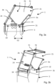
- FIGS. 1a and 1b show a firearm 100, of the assault rifle type, comprising a casing recovery device 1 arranged opposite the ejection window 110 (visible on the Figure 1b ) of cartridge cases fired.
- This ejection window 110 is more precisely arranged on a side part of the firearm 100.
- the firearm 100 also includes at least one mounting rail 104, such as a Picatinny rail, on which the user can install accessories such as a sighting optic.
- the firearm 100 notably comprises several fixing rails 104 including in particular upper, lower and lateral fixing rails.
- the cartridge case recovery device 1 more precisely comprises a recovery chamber 2 and a storage pocket 3 secured to each other.
- the recovery chamber 2 and the storage pocket 3 are movable between a cartridge case recovery position in which the recovery chamber 2 is intended to be opposite the ejection window 110, illustrated in Figure 1a , and a disengaged position in which the ejection window 110 is intended to be disengaged, illustrated in Figure 1b .
- the recovery chamber 2 comprises a first opening 21 intended to come opposite the ejection window 110 in the recovery position, and a second opening 22 connected to the storage pocket 3.
- the case recovery device 1 further comprises a fixing plate 4 arranged laterally relative to the recovery chamber 2 and comprising a first connection device 5 to the firearm 100.
- the case recovery device 1 also comprises a second connection device between the fixing plate 4 and the recovery chamber 2, one of the fifth lateral faces 2e of the recovery chamber 2.
- the second connection device comprising at least one slider 41, and at least one slide 42, arranged complementary and in which said slider 41 is guided between a first position in which the case recovery device 1 is in the recovery position and a second position in which the case recovery device 1 is in the released position.
- the casings ejected by the firearm 100 at its ejection window 110 are received by the recovery chamber 2 and are stored in the storage pocket 3.
- the recovery chamber 2 is moved relative to the ejection window 110 in order to allow access to the latter by the user in order, for example, to carry out a visual check of the ejection window or possibly to intervene on the latter in the event of a firing incident, without it being necessary to dismantle and detach the cartridge case recovery device 1.
- lower here is meant an element, here a face of the recovery chamber 2, intended to be arranged opposite the upper element, on the lower part of the recovery chamber 2 in the state mounted on the firearm 100 and when the firearm 100 is held normally.
- lateral is meant an element arranged on the sides of the front, rear, upper and lower elements simultaneously.
- the first face 2a called the front face, more particularly comprises the first opening 21 intended to come opposite the ejection window 110 in the recovery position.
- the dimensions of the first opening 21 are preferably equal to or greater than the ejection window 110 of the firearm 100.
- This first face 2a can thus comprise a rigid wall in which the first opening 21 is formed.
- a rigid wall may only be present on a part of the surface of the first face 2a, the first opening 21 being formed by the free space left by the rigid wall, advantageously on the upper part of the first face 2a.
- This rigid wall may in particular be made of a plastic material in order to limit the weight of the cartridge case recovery device 1.
- the first face 2a may be inclined relative to the plane of the firearm 100 so that its upper part is closer to the firearm 100 in the mounted state than its lower part.
- plane of the firearm 100 is meant the plane passing through the longitudinal axis A (visible in figures 1a and 1b) and passing through a handle 102 and/or an ammunition magazine 103 (visible in figures 1a and 1b). Figures 1a and 1b ) of said firearm 100.
- the second face 2b is arranged opposite the first face 2a.
- This second face 2b may in particular comprise, over its entire surface, a rigid wall against which the ejected casings are intended to come into contact before falling into the storage pocket 3.
- This rigid wall may in particular be made of a plastic material in order to limit the weight of the casing recovery device 1.
- the second face 2b may be inclined relative to the plane of the firearm 100 so that its upper part is closer to the firearm 100 in the mounted state than its lower part.
- the third face 2c connects more specifically an edge upper edge of the first face 2a to an upper edge of the second face 2b.
- This third face 2c may in particular comprise over its entire surface a wall, for example flexible, in order to prevent any casings from escaping through the upper face 2c.
- This wall is flexible makes it possible to limit the weight of the casing recovery device 1.
- This flexible wall may in particular be made of a high-strength, fire-retardant fabric.
- the fourth face 2d called lower, more particularly connects a lower edge of the first face 2a to a lower edge of the second face 2b.
- the fourth face 2d includes in particular the second opening 22 opening into the storage pocket 3. As illustrated in the Figures 3a and 3b , the fourth face 2b can be completely opened.
- the two fifth faces 2e connect lateral edges of the first face 2a, of the second face 2b, of the upper face 2c and of the lower face 2d.
- the case recovery device 1, in particular the recovery chamber 2 being intended to be fixed on a side of the firearm 100, depending on whether the ejection window 110 and therefore the case recovery device 1 is arranged on a right or left side of the firearm 100, one of the two fifth faces 2e is intended to be oriented towards the front of the firearm 100, that is to say towards the ejection mouth of the barrel of the firearm 100.
- the other fifth face 2e is oriented towards the rear of the firearm 100, that is to say towards the butt of the firearm 100.
- the storage pocket 3 is connected to the fourth face 2d of the recovery chamber 2.
- the storage pocket 3 has an opening 31 (visible on the Figures 3a and 3b ) connected to the second opening 22 of the fourth face 2d.
- the storage pocket 3 can in particular be made from a high-strength, military-grade fabric and more particularly fireproof in order to withstand the high temperature of the cartridges ejected by the firearm 100.
- said storage pocket 3 may comprise a bottom 32 comprising an opening device such as a zipper in order to be able to evacuate the casings and empty the storage pocket 3.
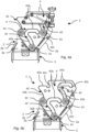
- the recovery chamber 2 may also comprise within it an inclined wall 24 arranged opposite the first face 2a of the recovery chamber 2 so that said first face 2a and said inclined wall 24 form a funnel converging towards the second opening 22.
- the gap E2 between the lower edge of the first face 2a of the recovery chamber 2 and the lower edge of the inclined wall 24 at the level of the second opening 22 may in particular be greater than 30% of the diameter of the casings intended to be recovered.
- This funnel formed between the first face 2a and the inclined wall 24 makes it possible to guide the casings into the storage pocket 3 but also allows the latter do not rise in the storage chamber 2 in the event of jolts or when the weapon is tilted forward or backward but also to the sides (by rotation around the axis A of the firearm 100).
- the attachment of the storage pocket 3 with the first face 2a of the recovery chamber 2 can be shifted forward, i.e. outward, so that the attachment of the storage pocket 3 on the first front face 2a is spaced from the edge of the second opening 22.
- This offset between the attachment of the storage pocket 3 and the edge of the second opening 22 creates a space between the storage pocket 3 and the second opening 22 which in particular makes it possible to prevent the cartridge cases from rolling and rising through the opening 31 of the storage pocket 3 and the second opening 22 of the recovery chamber 2 when the user tilts the firearm to the side, bringing the cartridge case recovery device 1 on top.
- the cases do not therefore rise into the recovery chamber 2, in this position, and do not hinder the ejection of other cases through the ejection window 110.
- the cartridge case recovery device 1 further comprises a means of attachment to the firearm 100, movable between the two recovery and released positions.
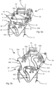
- Figures 4a, 4b And 6b show more particularly the cartridge case recovery device 1 in the released position and the Figures 5a, 5b And 6a show the cartridge case recovery device 1 in the recovery position.
- This fixing means comprises a fixing plate 4 arranged laterally relative to the recovery chamber 2.
- This fixing plate 4 comprises a first connection device 5 to the firearm 100.
- This first connection device 5 to the firearm 100 may in particular comprise a hooking means configured to hook onto a fixing rail 104 of the firearm 100 as illustrated in the Figures 4a , 5a And 6a, 6b
- the fixing rail 104 on which the first connection device 5 is intended to be attached is a lateral rail of the firearm 100 arranged behind the ejection window 110 relative to the user.
- the first connection device 5 can in particular be fixed to the fixing plate 4 by means of screws or bolts.
- the first connection device 5 may also comprise at least one positioning interface, for example extensions or extensions, making the connection between the fixing plate 4 and the means for attaching to the fixing rail 104.
- This at least one positioning interface allows the first connection device 5 to attach to the fixing rail 104 regardless of its positioning relative to the ejection window 110.
- the cartridge case recovery device 1 may thus be adapted to different firearms 100 with fixing rails 104 which may be in the axis of the ejection window 110 or offset relative to the axis of the ejection window 110.
- the attachment means of the first connection device 5 may in particular be a jaw attachment configured to attach to and grip the attachment rail 104.
- the means for attaching the cartridge case recovery device 1 to the firearm 100 further comprises a second connection device between the attachment plate 4 and one of the fifth lateral faces 2e of the recovery chamber 2.
- a second connection device between the attachment plate 4 and one of the fifth lateral faces 2e of the recovery chamber 2.
- the fifth lateral face 2e of the recovery chamber 2 on which the attachment plate 4 is attached will be different so that the first opening 21 of the recovery chamber 2 is opposite the ejection window 110.
- This second connection device comprises at least one slider 41, arranged on one or the other of the fixing plate 4 or one of the fifth lateral faces 2e of the recovery chamber 2, and at least one slide 42, arranged complementary on one or the other of one of the fifth lateral faces 2e of the recovery chamber 2 or of the fixing plate 4.
- the slider 41 is guided in the slide 42 between a first position in which the case recovery device 1 is in the recovery position and a second position in which the case recovery device 1 is in the released position.
- the second connection device may in particular comprise at least two slide 42 / slider 41 pairs parallel to each other.
- the second connection device more particularly comprises three slide 42 / slider 41 pairs parallel to each other in order to ensure good stability and a fluid translational movement to the recovery chamber 2 and to the storage pocket 3.
- the at least one slide 42 is produced on the fixing plate 4 and the at least one slider 41 is integral with one of the fifth lateral faces 2e of the recovery chamber 2. It is however entirely possible to imagine a second connection device in which the at least one slide 42 is produced on one of the fifth lateral faces 2e of the recovery chamber 2 and where the at least one slider 41 is integral with the fixing plate 4.
- the slides 42 may in particular be grooves provided in the fixing plate 4 or in the fifth lateral wall 2 carrying the second connection device. However, as illustrated in the various Figures 4a to 5b , when the slides 42 are produced on the fixing plate 4, one of these slides 42 may not be a groove but an open profile of an edge of the fixing plate 4 having the same shape as the other slides 42 and against which a slider 41 slides.
- the at least one slide 42 of the second connection device 4 can in particular comprising a first portion 42a configured to, in the mounted state, translate the recovery chamber 2 and the storage pocket 3 perpendicular to the plane of the firearm 100, so as to create a space E1 between the first opening 21 and the ejection window 110, as illustrated in Figures 6a and 6b
- This space E1 allows in particular access to the ejection window 110, particularly in the event of a firing incident or to check the latter.
- the at least one slide 42 of the second connection device may also comprise a second portion 42b contiguous to the first portion 42a and configured to, in the mounted state, translate the recovery chamber 2 and the storage pocket 3 parallel to the lateral plane of the firearm 100, so as to disengage the recovery chamber 2 from the ejection window 110.
- This translation of the recovery chamber 2 and the storage pocket 3 may in particular be oriented towards the bottom of the firearm 100, as illustrated in the Figure 1b , in order to completely clear the ejection window 110.
- This second portion 42b is connected to the end of the first portion 42a of the slide 42 furthest from the first face 2a of the recovery chamber 2.
- the second portion 42b of the slide 42 can be straight or curved as illustrated in the Figures 4a to 5b
- the second portion 42b of the slide 42 can in particular be inclined towards the first face 2a of the recovery chamber 2 so that in the released position, the recovery chamber 2 and the storage pocket 3 move closer to the side of the firearm 100.
- the first portion 42a of the at least one slide 42 of the second connection device may also comprise a recess 42c at one of its ends so that the slide 41 is positioned in said recess 42c in the recovery position.
- This recess 42c makes it possible to block the slide 41 in order to maintain the cartridge recovery device 1 in the recovery position.
- the case recovery device 1 can thus have the following kinematics when it passes from the recovery position to the released position in the state mounted on the firearm 100.
- the recovery chamber 2 as well as the storage pocket 3 are translated parallel to the plane of the firearm 100 upwards, that is to say towards the upper part of the firearm 100.
- This first translation makes it possible to cause the slide or slides 41 to come out of the recess 42c of the slide or slides 42.
- the recovery chamber 2 and the storage pocket 3 are then translated perpendicular to the plane of the firearm 100, following the first portion 42a of the slide or slides 42 in order to move the first opening 21 away from the ejection window 110.
- the recovery chamber 2 and the storage pocket 3 are then translated parallel to the plane of the firearm 100 upwards, that is to say towards the upper part of the firearm 100. fire 100 downwards, following the second portion 42b of the slide(s) 42 in order to completely clear the ejection window 110 so that nothing is facing the latter.
- the kinematics are reversed in order to move the case recovery device 1 from the released position to the recovery position.
- said cartridge case recovery device 1 may comprise a tab 25.
- This tab 25 may be made, for example, of reinforced fabric.
- this tab 25 may in particular be fixed to the upper side of the fifth lateral wall 2 carrying the second connection device.
- the cartridge case recovery device 1 may also include a locking device 44 (visible on the Figures 6a and 6b ) of the recovery chamber 2 and the storage pocket 3 in the recovery position.
- This locking device 44 may for example be a ball partially protruding from a housing here provided in the body of the first connection device 5. This ball may in particular be held by an elastic means, for example a spring. In the recovery position, the part of this ball protruding from its housing is inserted into a complementary cavity made at the end of a slide 41.
- one of the external walls i.e. the second rear wall 2b, the third upper wall 2c or the fifth lateral wall 2e without the means of attachment to the firearm 100, may be translucent.
- the translucent wall is the fifth lateral wall 2e without the means of attachment to the firearm 100 since the latter is arranged directly opposite the user in the state mounted on the firearm 100.
- case recovery device 1 allows the cases to be recovered, but that it also allows the latter to be kept in the storage pocket 3 regardless of the orientation of the firearm 100, in particular in order to limit the risks of these cases rising into the recovery chamber 2 and potentially hindering or jamming the ejection window 110.
- case recovery device 1 has two positions allows, if necessary, intervention on the ejection window 110 without having to detach the case recovery device 1 from the firearm 100.
Landscapes
- Engineering & Computer Science (AREA)
- General Engineering & Computer Science (AREA)
- Aiming, Guidance, Guns With A Light Source, Armor, Camouflage, And Targets (AREA)
- Toys (AREA)
Claims (13)
- Hülsenrückgewinnungsvorrichtung (1) für eine Feuerwaffe (100), beinhaltend ein Auswurffenster (110) für Hülsen der abgefeuerten Patronen, wobei die Hülsenrückgewinnungsvorrichtung (1) eine Rückgewinnungskammer (2) und einen Fangsack (3) umfasst, die fest miteinander verbunden sind und zwischen einer Position zur Rückgewinnung der Hülsen, in der die Rückgewinnungskammer (2) dazu bestimmt ist, sich gegenüber dem Auswurffenster (110) zu befinden, und einer abgerückten Position, in der das Auswurffenster (110) dazu bestimmt ist, abgerückt zu sein, beweglich sind, wobei die Rückgewinnungskammer (2) Folgendes beinhaltet:• eine erste Öffnung (21), die dazu bestimmt ist, in der Rückgewinnungsposition gegenüber dem Auswurffenster (110) zu liegen zu kommen, und• eine zweite Öffnung (22), die mit dem Fangsack (3) verbunden ist,wobei die Hülsenrückgewinnungsvorrichtung (1) ferner Folgendes umfasst:• eine Befestigungsplatte (4), die mit Bezug auf die Rückgewinnungskammer (2) seitlich angeordnet ist und eine erste Verbindungsvorrichtung (5) zu der Feuerwaffe (100) umfasst, und• eine zweite Verbindungsvorrichtung zwischen der Befestigungsplatte (4) und der Rückgewinnungskammer (2), dadurch gekennzeichnet, dass die zweite Verbindungsvorrichtung Folgendes umfasst:• mindestens einen Gleitstein (41) und• mindestens eine Führung (42), die komplementär angeordnet ist und in der der Gleitstein (41) zwischen einer ersten Position, in der sich die Hülsenrückgewinnungsvorrichtung (1) in der Rückgewinnungsposition befindet, und einer zweiten Position, in der sich die Hülsenrückgewinnungsvorrichtung (1) in der abgerückten Position befindet, geführt wird.
- Hülsenrückgewinnungsvorrichtung (1) nach dem vorhergehenden Anspruch, dadurch gekennzeichnet, dass die Rückgewinnungskammer (2) Folgendes beinhaltet:• eine erste Seite (2a), als Vorderseite bezeichnet, die die erste Öffnung (21) umfasst,• eine zweite Seite (2b), als Rückseite bezeichnet, die gegenüber der ersten Seite angeordnet ist,• eine dritte Seite (2c), als Oberseite bezeichnet, die einen oberen Rand der ersten Seite (2a) mit einem oberen Rand der zweiten Seite (2b) verbindet,• eine vierte Seite (2d), als Unterseite bezeichnet, die einen unteren Rand der ersten Seite (2a) mit einem unteren Rand der zweiten Seite (2b) verbindet, wobei die vierte Seite (2d) die zweite Öffnung (22) umfasst, die mit dem Fangsack (3) verbunden ist,• zwei fünfte Seiten (2e), als seitliche Seiten bezeichnet, die Seitenränder der ersten Seite (2a), der zweiten Seite (2b), der Oberseite (2c) und der Unterseite (2d) verbinden, undwobei die Befestigungsplatte (4) mit Bezug auf die Rückgewinnungskammer (2) seitlich angeordnet ist und die zweite Verbindungsvorrichtung an einer der fünften seitlichen Seiten (2e) der Rückgewinnungskammer (2) angeordnet ist.
- Hülsenrückgewinnungsvorrichtung (1) nach einem der vorhergehenden Ansprüche, dadurch gekennzeichnet, dass die erste Verbindungsvorrichtung (5) zu der Feuerwaffe (100) eine Backenhalterung umfasst, die dazu konfiguriert ist, mit einer Befestigungsschiene (104) gekoppelt zu werden.
- Hülsenrückgewinnungsvorrichtung (1) nach einem der vorhergehenden Ansprüche, dadurch gekennzeichnet, dass die erste Verbindungsvorrichtung (5) zu der Feuerwaffe (100) mindestens eine Positionierungsschnittstelle umfasst, die die Verbindung zwischen der Befestigungsplatte (4) und einem Mittel zum Koppeln mit der Befestigungsschiene (104) herstellt.
- Hülsenrückgewinnungsvorrichtung (1) nach einem der vorhergehenden Ansprüche, dadurch gekennzeichnet, dass die mindestens eine Führung (42) der zweiten Verbindungsvorrichtung (4) einen ersten Abschnitt (42a) umfasst, der dazu konfiguriert ist, die Rückgewinnungskammer (2) und den Fangsack (3) im montierten Zustand senkrecht zu der Ebene der Feuerwaffe (100) zu verschieben, um zwischen der ersten Öffnung (21) und dem Auswurffenster (110) ein Raum (E1) zu schaffen.
- Hülsenrückgewinnungsvorrichtung (1) nach dem vorhergehenden Anspruch, dadurch gekennzeichnet, dass die mindestens eine Führung (42) der zweiten Verbindungsvorrichtung einen zweiten Abschnitt (42b) umfasst, der an den ersten Abschnitt (42a) angrenzt und dazu konfiguriert ist, die Rückgewinnungskammer (2) und den Fangsack (3) im montierten Zustand parallel zu der Ebene der Feuerwaffe (100) zu verschieben, um die Rückgewinnungskammer (2) von der dem Auswurffenster (110) gegenüberliegenden Stellung abzurücken.
- Hülsenrückgewinnungsvorrichtung (1) nach einem der Ansprüche 5 oder 6, dadurch gekennzeichnet, dass der erste Abschnitt (42a) der mindestens einen Führung (42) der zweiten Verbindungsvorrichtung an einem seiner Enden einen Absatz (42c) umfasst, sodass der Gleitstein (41) in der Rückgewinnungsposition in dem Absatz (42c) positioniert ist.
- Hülsenrückgewinnungsvorrichtung (1) nach einem der vorhergehenden Ansprüche, dadurch gekennzeichnet, dass sie eine Vorrichtung zum Verriegeln (44) der Rückgewinnungskammer (2) und des Fangsacks (3) in der Rückgewinnungsposition umfasst.
- Hülsenrückgewinnungsvorrichtung (1) nach einem der vorhergehenden Ansprüche, dadurch gekennzeichnet, dass die zweite Verbindungsvorrichtung mindestens zwei Paare aus einer Führung (42) / einem Gleitstein (41) umfasst, die zueinander parallel sind.
- Hülsenrückgewinnungsvorrichtung (1) nach einem der Ansprüche 2 bis 9, dadurch gekennzeichnet, dass die Rückgewinnungskammer (2) in ihrem Inneren eine geneigte Wand (24) umfasst, die gegenüber der ersten Seite (2a) der Rückgewinnungskammer (2) angeordnet ist, sodass die erste Seite (2a) und die geneigte Wand (24) einen Trichter bilden, der zu der zweiten Öffnung (22) konvergiert.
- Hülsenrückgewinnungsvorrichtung (1) nach dem vorhergehenden Anspruch, dadurch gekennzeichnet, dass der Abstand (E2) zwischen dem unteren Rand der ersten Seite (2a) der Rückgewinnungskammer (2) und dem unteren Rand der geneigten Wand (24) im Bereich der zweiten Öffnung (22) bis zu 30 % größer ist als der Durchmesser der Hülsen, die zurückgewonnen werden sollen.
- Hülsenrückgewinnungsvorrichtung (1) nach einem der Ansprüche 2 bis 11, dadurch gekennzeichnet, dass die Befestigung des Fangsacks (3) an der ersten Seite (2a) der Rückgewinnungskammer (2) nach vorne versetzt ist, sodass die Befestigung des Fangsacks (3) an der ersten Vorderseite (2a) von dem Rand der zweiten Öffnung (22) beabstandet ist.
- Hülsenrückgewinnungsvorrichtung (1) nach einem der vorhergehenden Ansprüche, dadurch gekennzeichnet, dass eine der Außenwände (2b, 2c, 2e) der Rückgewinnungskammer (2) transluzent ist.
Applications Claiming Priority (1)
| Application Number | Priority Date | Filing Date | Title |
|---|---|---|---|
| FR2207273A FR3137963B1 (fr) | 2022-07-15 | 2022-07-15 | Dispositif récupérateur de douilles pour arme à feu |
Publications (3)
| Publication Number | Publication Date |
|---|---|
| EP4306897A1 EP4306897A1 (de) | 2024-01-17 |
| EP4306897B1 true EP4306897B1 (de) | 2025-04-09 |
| EP4306897C0 EP4306897C0 (de) | 2025-04-09 |
Family
ID=84362777
Family Applications (1)
| Application Number | Title | Priority Date | Filing Date |
|---|---|---|---|
| EP23183908.5A Active EP4306897B1 (de) | 2022-07-15 | 2023-07-06 | Hülsenrückgewinnungsvorrichtung für eine feuerwaffe |
Country Status (2)
| Country | Link |
|---|---|
| EP (1) | EP4306897B1 (de) |
| FR (1) | FR3137963B1 (de) |
Family Cites Families (3)
| Publication number | Priority date | Publication date | Assignee | Title |
|---|---|---|---|---|
| CH680533A5 (de) * | 1989-08-29 | 1992-09-15 | Timour Bammate | |
| US7168200B2 (en) * | 2004-11-12 | 2007-01-30 | Kenneth Perez | Gun shell catcher device |
| US20120023803A1 (en) * | 2010-07-12 | 2012-02-02 | Sidney Bernard Taylor | Magazine Mounted Spent Shell Receptacle |
-
2022
- 2022-07-15 FR FR2207273A patent/FR3137963B1/fr active Active
-
2023
- 2023-07-06 EP EP23183908.5A patent/EP4306897B1/de active Active
Also Published As
| Publication number | Publication date |
|---|---|
| EP4306897A1 (de) | 2024-01-17 |
| FR3137963B1 (fr) | 2024-06-14 |
| EP4306897C0 (de) | 2025-04-09 |
| FR3137963A1 (fr) | 2024-01-19 |
Similar Documents
| Publication | Publication Date | Title |
|---|---|---|
| EP0344520B1 (de) | Patronenhülsensammler für Feuerwaffen mit Schulterstütze | |
| CH686098A5 (fr) | Dispositif de recuperation des etuis de cartouches pour une arme automatique ou semi-automatique. | |
| EP0708908B1 (de) | Feuerwaffe mit gelenkigem magazin | |
| EP1349451B1 (de) | Unterwasserharpune vom armbrusttyp mit spannvorrichtung | |
| EP1003007B1 (de) | Abzugsmechanismus für Feuerwaffen | |
| EP0470012A1 (de) | Einschüssige Handfeuerwaffe | |
| EP3682183B1 (de) | Maschinengewehr | |
| EP3682182B1 (de) | Maschinengewehr | |
| BE1004981A3 (fr) | Chargeur a basculement de cartouches pour pistolet ou pistolet mitrailleur. | |
| EP3169967B1 (de) | Halfter für eine handfeuerwaffe mit einem abzugbügel und einem lauf | |
| EP4306897B1 (de) | Hülsenrückgewinnungsvorrichtung für eine feuerwaffe | |
| EP3682184B1 (de) | Maschinengewehr | |
| EP3421924A1 (de) | Patronenhülsensammelvorrichtung für feuerwaffe | |
| BE399933A (de) | ||
| EP0661514B1 (de) | Waffe mit bewegbaren Verschlussstücken | |
| EP0415054B1 (de) | Patronenhülsensammler für Schulterwaffen | |
| EP3477239A1 (de) | Maschinengewehr | |
| EP3477242A1 (de) | Maschinengewehr | |
| EP3682185B1 (de) | Maschinengewehr | |
| FR2783598A1 (fr) | Arme a tube de gros calibre | |
| EP3477243A1 (de) | Maschinengewehr | |
| EP3477241A1 (de) | Maschinengewehr | |
| FR2617585A1 (fr) | Dispositif de commande de mise a feu pour arme automatique et procede de montage du dispositif sur l'arme | |
| WO2006040420A1 (fr) | Dispositif adaptateur pivotant pour chargeur de differente capacite | |
| FR2856787A1 (fr) | Etui souple pour arme de chasse |
Legal Events
| Date | Code | Title | Description |
|---|---|---|---|
| PUAI | Public reference made under article 153(3) epc to a published international application that has entered the european phase |
Free format text: ORIGINAL CODE: 0009012 |
|
| STAA | Information on the status of an ep patent application or granted ep patent |
Free format text: STATUS: THE APPLICATION HAS BEEN PUBLISHED |
|
| AK | Designated contracting states |
Kind code of ref document: A1 Designated state(s): AL AT BE BG CH CY CZ DE DK EE ES FI FR GB GR HR HU IE IS IT LI LT LU LV MC ME MK MT NL NO PL PT RO RS SE SI SK SM TR |
|
| STAA | Information on the status of an ep patent application or granted ep patent |
Free format text: STATUS: REQUEST FOR EXAMINATION WAS MADE |
|
| 17P | Request for examination filed |
Effective date: 20240709 |
|
| RBV | Designated contracting states (corrected) |
Designated state(s): AL AT BE BG CH CY CZ DE DK EE ES FI FR GB GR HR HU IE IS IT LI LT LU LV MC ME MK MT NL NO PL PT RO RS SE SI SK SM TR |
|
| GRAP | Despatch of communication of intention to grant a patent |
Free format text: ORIGINAL CODE: EPIDOSNIGR1 |
|
| STAA | Information on the status of an ep patent application or granted ep patent |
Free format text: STATUS: GRANT OF PATENT IS INTENDED |
|
| INTG | Intention to grant announced |
Effective date: 20241126 |
|
| GRAS | Grant fee paid |
Free format text: ORIGINAL CODE: EPIDOSNIGR3 |
|
| GRAA | (expected) grant |
Free format text: ORIGINAL CODE: 0009210 |
|
| STAA | Information on the status of an ep patent application or granted ep patent |
Free format text: STATUS: THE PATENT HAS BEEN GRANTED |
|
| AK | Designated contracting states |
Kind code of ref document: B1 Designated state(s): AL AT BE BG CH CY CZ DE DK EE ES FI FR GB GR HR HU IE IS IT LI LT LU LV MC ME MK MT NL NO PL PT RO RS SE SI SK SM TR |
|
| REG | Reference to a national code |
Ref country code: GB Ref legal event code: FG4D Free format text: NOT ENGLISH |
|
| REG | Reference to a national code |
Ref country code: CH Ref legal event code: EP |
|
| REG | Reference to a national code |
Ref country code: DE Ref legal event code: R096 Ref document number: 602023002807 Country of ref document: DE |
|
| REG | Reference to a national code |
Ref country code: IE Ref legal event code: FG4D Free format text: LANGUAGE OF EP DOCUMENT: FRENCH |
|
| U01 | Request for unitary effect filed |
Effective date: 20250505 |
|
| U07 | Unitary effect registered |
Designated state(s): AT BE BG DE DK EE FI FR IT LT LU LV MT NL PT RO SE SI Effective date: 20250509 |
|
| U20 | Renewal fee for the european patent with unitary effect paid |
Year of fee payment: 3 Effective date: 20250730 |
|
| PG25 | Lapsed in a contracting state [announced via postgrant information from national office to epo] |
Ref country code: ES Free format text: LAPSE BECAUSE OF FAILURE TO SUBMIT A TRANSLATION OF THE DESCRIPTION OR TO PAY THE FEE WITHIN THE PRESCRIBED TIME-LIMIT Effective date: 20250409 |
|
| PG25 | Lapsed in a contracting state [announced via postgrant information from national office to epo] |
Ref country code: GR Free format text: LAPSE BECAUSE OF FAILURE TO SUBMIT A TRANSLATION OF THE DESCRIPTION OR TO PAY THE FEE WITHIN THE PRESCRIBED TIME-LIMIT Effective date: 20250710 |
|
| PGFP | Annual fee paid to national office [announced via postgrant information from national office to epo] |
Ref country code: NO Payment date: 20250725 Year of fee payment: 3 |
|
| PG25 | Lapsed in a contracting state [announced via postgrant information from national office to epo] |
Ref country code: PL Free format text: LAPSE BECAUSE OF FAILURE TO SUBMIT A TRANSLATION OF THE DESCRIPTION OR TO PAY THE FEE WITHIN THE PRESCRIBED TIME-LIMIT Effective date: 20250409 |
|
| PG25 | Lapsed in a contracting state [announced via postgrant information from national office to epo] |
Ref country code: HR Free format text: LAPSE BECAUSE OF FAILURE TO SUBMIT A TRANSLATION OF THE DESCRIPTION OR TO PAY THE FEE WITHIN THE PRESCRIBED TIME-LIMIT Effective date: 20250409 |
|
| PG25 | Lapsed in a contracting state [announced via postgrant information from national office to epo] |
Ref country code: RS Free format text: LAPSE BECAUSE OF FAILURE TO SUBMIT A TRANSLATION OF THE DESCRIPTION OR TO PAY THE FEE WITHIN THE PRESCRIBED TIME-LIMIT Effective date: 20250709 |
|
| PG25 | Lapsed in a contracting state [announced via postgrant information from national office to epo] |
Ref country code: IS Free format text: LAPSE BECAUSE OF FAILURE TO SUBMIT A TRANSLATION OF THE DESCRIPTION OR TO PAY THE FEE WITHIN THE PRESCRIBED TIME-LIMIT Effective date: 20250809 |
|
| PG25 | Lapsed in a contracting state [announced via postgrant information from national office to epo] |
Ref country code: SM Free format text: LAPSE BECAUSE OF FAILURE TO SUBMIT A TRANSLATION OF THE DESCRIPTION OR TO PAY THE FEE WITHIN THE PRESCRIBED TIME-LIMIT Effective date: 20250409 |
|
| PG25 | Lapsed in a contracting state [announced via postgrant information from national office to epo] |
Ref country code: CZ Free format text: LAPSE BECAUSE OF FAILURE TO SUBMIT A TRANSLATION OF THE DESCRIPTION OR TO PAY THE FEE WITHIN THE PRESCRIBED TIME-LIMIT Effective date: 20250409 |
|
| PG25 | Lapsed in a contracting state [announced via postgrant information from national office to epo] |
Ref country code: SK Free format text: LAPSE BECAUSE OF FAILURE TO SUBMIT A TRANSLATION OF THE DESCRIPTION OR TO PAY THE FEE WITHIN THE PRESCRIBED TIME-LIMIT Effective date: 20250409 |
|
| PLBE | No opposition filed within time limit |
Free format text: ORIGINAL CODE: 0009261 |
|
| STAA | Information on the status of an ep patent application or granted ep patent |
Free format text: STATUS: NO OPPOSITION FILED WITHIN TIME LIMIT |
|
| REG | Reference to a national code |
Ref country code: CH Ref legal event code: L10 Free format text: ST27 STATUS EVENT CODE: U-0-0-L10-L00 (AS PROVIDED BY THE NATIONAL OFFICE) Effective date: 20260218 |
|
| 26N | No opposition filed |
Effective date: 20260112 |