EP4345210B1 - Dispositif de support de rails pour le support insonorisant d'un rail - Google Patents
Dispositif de support de rails pour le support insonorisant d'un rail Download PDFInfo
- Publication number
- EP4345210B1 EP4345210B1 EP23199582.0A EP23199582A EP4345210B1 EP 4345210 B1 EP4345210 B1 EP 4345210B1 EP 23199582 A EP23199582 A EP 23199582A EP 4345210 B1 EP4345210 B1 EP 4345210B1
- Authority
- EP
- European Patent Office
- Prior art keywords
- damping means
- ribbed plate
- rail
- frame
- underside
- Prior art date
- Legal status (The legal status is an assumption and is not a legal conclusion. Google has not performed a legal analysis and makes no representation as to the accuracy of the status listed.)
- Active
Links
Images


Classifications
-
- E—FIXED CONSTRUCTIONS
- E01—CONSTRUCTION OF ROADS, RAILWAYS, OR BRIDGES
- E01B—PERMANENT WAY; PERMANENT-WAY TOOLS; MACHINES FOR MAKING RAILWAYS OF ALL KINDS
- E01B9/00—Fastening rails on sleepers, or the like
- E01B9/62—Rail fastenings incorporating resilient supports
-
- E—FIXED CONSTRUCTIONS
- E01—CONSTRUCTION OF ROADS, RAILWAYS, OR BRIDGES
- E01B—PERMANENT WAY; PERMANENT-WAY TOOLS; MACHINES FOR MAKING RAILWAYS OF ALL KINDS
- E01B19/00—Protection of permanent way against development of dust or against the effect of wind, sun, frost, or corrosion; Means to reduce development of noise
- E01B19/003—Means for reducing the development or propagation of noise
Definitions
- the present invention relates to a rail support device for sound-damping support and fastening of a rail, comprising a ribbed plate for arranging the rail on an upper surface of the ribbed plate, a first damping means, and a frame.
- the first damping means can be designed as an elastomer bearing and is arranged between the ribbed plate and the frame to dampen the ribbed plate.
- Cologne Egg refers to a rail fastening system that reduces structure-borne noise. Structure-borne noise, in turn, is the cause of secondary airborne noise in buildings adjacent to or above railway lines.
- the name "Cologne Egg” is derived both from the oval shape of the rail support system used in practice and from the city name of C perfume, as this type of fastening system was first developed and used in C perfume.
- the DE 28 32 989 C2 which describes the functional principle of the sound-absorbing rail bearing.
- the basis for this sound-absorbing rail bearing is the DE 28 28 714 A1 described device for sound-insulating storage of heavy components.
- Both the ribbed plate and the frame may be made of metal, these two metal parts being connected to each other by vulcanization, namely by or via the first damping means.
- the frame can be provided with lugs with holes for attachment to the substructure with sleeper screws or threaded fittings.
- the ribbed plate can be supported by the first damping element, which can preferably be a vulcanized elastomer.
- the first damping element in turn, can be supported on the frame.
- the construction of the "Cologne Egg” type rail support system known from practice has a maximum installation height of at least approximately 76 mm.
- the installation height is understood to be the distance from the underside of the frame to the top of the ribbed plate, whereby the ribs or the height of the ribbed plate's ribs are not taken into account when determining the installation height. Since it is also known from practice that the top of the ribbed plate runs at an angle to the subsurface and/or at an angle to the underside of the frame, the maximum installation height is understood to be the installation height at the highest point of the top of the ribbed plate.
- the DE 199 24 891 C1 discloses a sound-absorbing rail support intended for a rail belonging to a track.
- the rail support comprises a rail support plate for supporting the rail and a frame for attaching the rail support to a support surface.
- the EP 0 236 703 A2 relates to a rail bearing having a first and second damping means.
- the DE 29 33 541 A1 also concerns a rail bearing.
- the US 2018/016754 A1 concerns a rail bearing with a damping agent.
- the object of the present invention is to avoid the aforementioned disadvantages of the prior art or at least to substantially reduce them.
- the rail support device has a ribbed plate for arranging the rail on an upper side of the ribbed plate.
- the ribbed plate can have at least two ribs between which the rail can be enclosed.
- the rail support device further comprises a first damping means, which is designed in particular as an elastomer bearing or as an elastic bearing, in particular a rubber-elastic bearing.
- the rail support device comprises a frame, which delimits the rail support device, in particular on the outside.
- the first damping means is arranged between the ribbed plate and the frame. In particular, the first damping means separates the ribbed plate from the frame, preferably completely and/or circumferentially.
- the invention provides that a further damping means is provided below the ribbed plate to limit deflection.
- the additional damping means can be provided and arranged separately from the first damping means. However, in further embodiments of the invention, it is also possible for the additional damping means to be connected to the first damping means.
- the additional damping means is particularly designed to ensure a limit on deflection.
- the springing or damping of the "Cologne Egg” is provided solely by the first damping means. Due to the arrangement and design of the first damping means in the prior art, a certain height and width of the first damping means must be provided so that the damping properties necessary to reduce structure-borne noise can be ensured. According to the invention, it is now possible for not only the first damping means to be provided to reduce structure-borne noise and limit deflection. The additional damping means can then also contribute to the damping properties or at least partially ensure them as well.
- the structure-borne sound reduction achieved by the known "Cologne Egg” can be maintained or even improved.
- the invention provides the significant advantage that the installation height can be significantly reduced, preferably by at least 10%, compared to rail bearing devices of the "Cologne Egg" system known from the prior art.
- Such a reduction in installation height also offers the advantage that it is possible to use rail support systems based on the "Cologne Egg” system in sections and/or areas that require an installation height of less than 76 mm due to the existing rail support system. Accordingly, complex subsurface preparation is eliminated, so that the rail support system according to the invention can be installed comparatively easily in existing rail support systems. This increases the flexibility of the "Cologne Egg” and also creates the possibility of integrating the "Cologne Egg” into a variety of existing rail support systems, which was not possible before the invention due to the specified increased installation height of the "Cologne Egg” known from the prior art.
- the deflection limiter ensures, in particular, that the ribbed plate can only be lowered to a certain height, which is understood in the invention as deflection limiter.
- This distance or this variable height difference of the deflection limiter can result, on the one hand, from the material properties of the first damping means and/or the additional damping means, as well as from a distance between the underside of the additional damping means and the ground.
- the first damping element provides appropriate damping when the ribbed plate is loaded, thus ensuring the spring properties.
- the first damping element in addition to the other damping element, also contributes to limiting deflection.
- a deflection limitation in the range between 1 and 15 mm, preferably between 2 and 10 mm, and in particular of 4 mm +/- 1 mm, can be provided.
- Such a deflection limitation enables effective and reliable damping of structure-borne noise and thus contributes to the stability of buildings located near the rail.
- the rail support device can be used with the same or improved structure-borne sound reduction properties as the "Cologne Egg” known from the prior art, but in particular can ensure a lower installation height.
- the rail support device according to the invention is preferably particularly easy to integrate into existing rail systems.
- the additional damping means, the first damping means, the ribbed plate, and the frame are firmly connected to one another, in particular by a material bond, preferably by vulcanizing the damping means. This allows this structural unit to be handled as a compact, coherent unit, thus avoiding errors during assembly of the rail support device.
- the frame preferably has a recess for arranging the first damping means and the ribbed plate.
- the recess can be designed as an opening.
- the recess serves to accommodate the first damping means, in particular wherein the first damping means rests circumferentially on the inner wall of the recess, preferably being firmly connected to it, preferably vulcanized thereto.
- Such vulcanization makes it possible to handle the frame and the first damping means as a common assembly, as already explained above.
- the additional damping means is adjacent to the underside of the ribbed plate, in particular rests against it, and/or is connected to it.
- the additional damping means can be integrally connected to the underside of the ribbed plate.
- the additional damping means is vulcanized to the underside of the ribbed plate, at least in some areas, preferably completely.
- the additional damping means can be designed to rest on the ground and be spaced apart from the underside of the ribbed plate.
- the overall deflection limitation achieved is determined partly by the material of the damping means and partly by the distance or gap between the upper side of the additional damping means and the underside of the ribbed plate.
- the achieved deflection limitation results in particular from the distance between the underside of the additional damping means and the material properties of the additional damping means or damping means, as already explained at the beginning.
- the first damping means and/or the further damping means comprise an elastomer, in particular a synthetic rubber, and/or an elastic, preferably rubber-elastic, material.
- Natural rubber (NR) can be provided as the elastic, in particular rubber-elastic, material.
- the further damping means is preferably made of natural rubber.
- the provision of the first damping means and the additional damping means according to the invention makes it possible to individually adjust the damping or spring properties of the rail support device to different applications. Such adjustment can also be achieved by selecting the material of the damping means.
- the materials of the first damping means and the additional damping means can be at least substantially identical.
- the first damping means could comprise a different material than the additional damping means.
- the first damping means could comprise an elastomer, in particular a synthetic rubber, whereas the additional damping means could comprise a natural rubber.
- Different additives of the materials for the first and the additional damping means are also conceivable according to the invention.
- the first damping means has at least substantially the same hardness as, or a different hardness than, the hardness of the additional damping means. Adjusting the hardness can also ensure that specific damping properties of the first and additional damping means can be specifically ensured and thus utilized – each for the optimal application and for improved rail support.
- the additional damping means has a Shore A hardness (in particular according to DIN EN ISO 868 and/or DIN ISO 7619, as of September 2022) between 40 and 80, preferably between 45 and 50, and in particular 50 +/- 20%.
- the aforementioned Shore hardnesses enable a rubber-elastic design of the additional damping means and, at the same time, also limit the deflection of the ribbed plate.
- the aforementioned damping properties of the first and the further damping means make it possible to provide the particularly advantageous properties of reducing structure-borne noise by the "Cologne Egg” also in the rail bearing device according to the invention, which is preferably to be regarded as a further development of the "Cologne Egg".
- a recess is provided on the underside of the ribbed plate to accommodate the additional damping means.
- the recess is designed such that, in the unloaded state of the rail support device, the underside of the additional damping means is spaced from the ground or a gap is provided, preferably of at least 0.5 mm, preferably between 1 to 10 mm, more preferably between 1.5 to 2.5 mm.
- the recess is designed to be complementary—in terms of dimensions—to the additional damping means.
- the additional damping means protrudes at least partially beyond the recess and thus beyond the ribbed plate.
- the further damping means can in particular at least substantially completely fill the surface of the recess of the ribbed plate.
- the recess can be provided, in particular, by appropriately machining a ribbed plate already known from the prior art, thus enabling the adaptation of a known ribbed plate for use in a rail support device according to the invention.
- Ribbed plates with a corresponding recess can also be manufactured in the factory during production.
- the additional damping means comprises a plurality of projections, in particular configured as knobs.
- the projections can protrude or protrude from a base surface facing the underside of the ribbed plate.
- the projections can, in particular, protrude beyond the recess.
- the projections may be formed at least partially, preferably entirely, as solid bodies. This solid design allows for optimal damping properties to be provided for the rail support device.
- the design of the projections allows the projections to be compressed when the ribbed plate is subjected to a corresponding load, thus enabling a corresponding load transfer, particularly when the underside of the projections is already in contact with the subsurface or when the top of the base surface is in contact with the underside of the ribbed plate.
- Whether the underside of the projections is in contact with the subsurface or the top of the base surface is in contact with the underside of the ribbed plate depends on whether the base surface is in contact with the underside of the Ribbed plate is firmly connected or not.
- the projections and their spacing thus ensure that the material can expand accordingly under load and provide the deflection limitation according to the invention, in particular without causing material stress on the ribbed plate or the frame.
- the projections can also be firmly connected to the base plate and/or formed as one piece therewith.
- the projections can be essentially identical or different in design.
- An identical arrangement allows for the additional damping element to be manufactured relatively easily and cost-effectively, ensuring optimal damping properties.
- the subsurface is formed by the plane spanned by the underside of the frame facing away from the rail - especially in the unloaded state of the rail support device.
- the additional damping means comprises between 2 and 30, more preferably between 3 and 20, and preferably between 4 and 10, projections.
- the projections may extend over at least 10%, preferably between 10% and 90%, more preferably between 20% and 40%, and in particular between 30% and 70%, of the surface of the base area.
- the fact that the projections do not extend over the entire surface of the base area also ensures that the projections are spaced apart from one another.
- the distance between two immediately adjacent projections may vary and, in particular, be provided in accordance with the desired damping properties.
- the projections have an at least substantially cylindrical and/or at least substantially conical, preferably truncated cone, shape.
- the conical shape offers the advantage that, when the projections are loaded, an excessive widening can be counteracted with a corresponding material expansion.
- the conical shape provides the optimal damping properties of the Damping means when used for the rail support device.
- the projections taper conically from the base surface to the underside of the additional damping means, which faces the substrate. Accordingly, the outer diameter of the projections in the area of the substrate or facing the substrate can be smaller than the outer diameter of the projections in the area of the base surface. This makes it possible to compensate for material expansion of the projections when the projections are loaded.
- the damping means has projections arranged in rows, wherein projections can also be arranged outside a row.
- Projections arranged in a row can in particular have at least substantially the same distance from one another.
- the rows are equidistant from one another.
- at least three projections are arranged in at least two rows and further projections are provided outside these rows, wherein in this case, in particular, a constant distance is not included between each pair of immediately adjacent projections.
- the projections can be arranged on the base surface in such a way as to result in optimal damping behavior of the further damping means.
- the thickness of the base surface can also be provided depending on the height of the projections.
- the material thickness of the base surface of the additional damping means can correspond to at least 1%, preferably between 1% and 60%, more preferably between 5% and 20%, and in particular between 10% and 15% of the maximum height of the projections.
- the material thickness of the base surface can, in particular, be at least substantially constant.
- the rail support device has a maximum installation height of at least 40 mm, preferably between 40 and 70 mm, more preferably between 50 and 60 mm.
- the installation height can be provided according to customer specifications. As previously explained, in this context, the installation height is determined by the Distance from the bottom of the frame to the top of the rib plate (excluding the ribs of the rib plate).
- top of the ribbed plate can also be inclined to the substructure and/or to the underside of the frame when installed.
- the maximum installation height is understood to be the greatest height.
- the minimum installation height (i.e. the lowest installation height) in the assembled state is at least 30 mm, in particular between 30 and 60 mm, more preferably between 40 and 50 mm.
- the distance between the minimum and maximum installation heights can vary depending on the size or length of the rail support device. In particular, a distance of at least 5 mm, preferably between 5 and 15 mm, more preferably between 6 and 10 mm, can be provided between the maximum and minimum installation heights.
- the angle of inclination between the top side of the ribbed plate and the substrate or the underside of the frame can be at least 0.5°, preferably between 0.5° and 3°, more preferably between 1° and 2° and in particular 1.4° +/- 15%.
- the first damping means extends with a support section over the height of the frame.
- the first damping means extends from the top of the frame to the bottom of the frame and also particularly preferably rests with the support section on the ground.
- the first damping means protrudes from the top of the frame.
- the support section can rest on the top of the frame and/or, at least in certain areas, directly against the top of the frame. This allows the forces generated when the ribbed plate is loaded to be transferred into the frame and, via the frame, into the substructure.
- the first damping element also dampens the load on the ribbed plate and leads to a reduction in structure-borne noise.
- an arrangement section of the first damping means is provided adjacent to the support section.
- the arrangement section is spaced from the underside of the support section and has a Receptacle for arranging the ribbed plate.
- the arrangement section protrudes from the support section on the upper side and/or the underside of the further damping means protrudes from the underside of the arrangement section.
- the ribbed plate has a circumferential support region at its edge, wherein the support region is arranged in the receptacle of the arrangement section of the first damping means.
- the support region of the ribbed plate encloses the recess of the ribbed plate.
- the support region can enable the transition between the first and the further damping means arranged in the recess.
- the inner longitudinal side of the frame facing the first damping means or the inner wall of the frame and/or the outer longitudinal side of the first damping means facing the inner longitudinal side of the frame lie directly against one another and/or extend at an angle ⁇ of 40° to 85°, preferably of 70° to 80°, to the underside of the frame.
- the aforementioned angle enables the forces occurring during loading to be optimally introduced into the frame and the substructure, and no undesired tensions arise in the entire rail support device. If the angle ⁇ were formed at a right angle, this would result in a disadvantageous dissipation of the forces, whereby the inclined arrangement enables the forces to be introduced into the substructure in an efficient manner.
- the angle ⁇ faces away from the ribbed plate, so that it is understood that a further angle (180° - ⁇ ) exists between the inner longitudinal side of the frame facing the first damping means and/or the outer longitudinal side of the first damping means facing the inner longitudinal side of the frame and the underside of the frame, which faces the ribbed plate.
- the angle ⁇ is preferably at least substantially constant all the way around the frame or all the way around the ribbed plate.
- the longitudinal section of the inner longitudinal side of the first damping means which is arranged directly on the longitudinal side of the ribbed plate and faces the ribbed plate, and/or the outer longitudinal side of the ribbed plate facing the first damping means, extends/extends at an angle ⁇ of 40° to 85°, preferably of 70° to 80°, to the underside of the frame.
- the angle ⁇ also enables the aforementioned advantageous properties in the Loading of the rail support device.
- the angles ⁇ and ⁇ are at least substantially equal, which enables the symmetry of the rail support device and can ensure optimized force introduction.
- first damping means completely delimits the ribbed plate from the frame.
- the first damping means can also be formed circumferentially around the ribbed plate.
- the rail can be fastened to ribs of the ribbed plate, preferably via corresponding tension clamps and threaded screws.
- clamping devices in particular tension clamps, can be provided for fastening the rail, which can be firmly connected to the ribbed plate by corresponding connecting means, such as threaded screws, thereby clamping the rail to the ribbed plate.
- the frame in turn, can be firmly screwed or force-locked to the substrate using appropriate fasteners, in particular threaded screws.
- the frame and the damping means completely enclose the ribbed plate circumferentially.
- the ribbed plate and/or the recess and/or the first and/or the further damping means have an oval shape in cross-section, in particular the shape of an ellipse.
- the longitudinal axis of the ellipse of the ribbed plate, the recess and/or the damping means is arranged at least substantially at a right angle to the longitudinal axis of the rail.
- the respective longitudinal axis is at least essentially in the direction of the greatest longitudinal extent of the respective body.
- An orthogonal alignment of the longitudinal axis of the ellipse and the longitudinal axis of the rail makes it possible to arrange the rail on the rail bearing in such a way that the optimal damping properties can be provided and the rail is mounted safely and permanently.
- the first damping means extends with a support section over the height of the frame to the underside of the frame for resting on the ground.
- This inventive idea is proposed in particular independently of the further damping means to achieve the inventive object.
- a direct arrangement of the first damping means on the ground makes it possible to directly introduce the forces to be cushioned when the ribbed plates are loaded into the ground via the first damping means, thereby increasing the flexibility of use and further reducing the installation height of the entire rail support device.
- Fig. 1 shows a rail support device 1 for sound-damping support and fastening of a rail 2.
- the rail support device 1 has a ribbed plate 3, which in the illustrated embodiment comprises two ribs 28.
- the rail bearing device 1 further comprises a first damping means 6, which can be designed in particular as an elastomer bearing, and a frame 7.
- the Fig. 2 shows a schematic plan view of a rail storage device 1. From the Fig. 2 It can be seen that the first damping means 6 is arranged between the ribbed plate 3 and the frame 7.
- the ribbed plate 3 serves to arrange the rail 2 on an upper side 4 of the ribbed plate 3.
- the rail 2 is firmly attached, in particular clamped, to the ribbed plate 3.
- tension clamps 29 can be used, which are firmly connected to the ribbed plate 3 via threaded screws 30, which can be fastened with a nut 31. This is also evident from the schematic perspective view of the rail support device 1 according to the Figs. 13 and 14 visible.
- Fig. 13 is a schematic representation of the braced rail 2 on the ribbed plate 3.
- the ribs 28 of the ribbed plate 3 can be perforated, as is the case with the Fig. 16
- the breakthrough can be achieved via an opening 39 be realized, whereby the opening 39 can serve for the arrangement of tension clamps 29 and threaded screws 30, as the schematic perspective representation of a ribbed plate 3 according to Fig. 16 clarified.
- the rail 2 is fastened with its longitudinal axis G to the rail support device 1.
- the longitudinal axis L of the ribbed plate 3 runs at least substantially orthogonal to the longitudinal axis G of the rail 2. This is shown schematically in the Fig. 2 shown.
- the Fig. 2 clarifies that the first damping means 6 circumferentially delimits the ribbed plate 3 at least substantially completely from the frame 7. Direct contact of the frame 7 with the ribbed plate 3 can be prevented by the arrangement of the first damping means 6.
- first damping means 6 can be firmly connected to the frame 7 and/or the ribbed plate 3, preferably by means of a material bond, in particular by vulcanization.
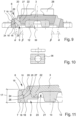
- the design of the first damping means 6 as an intermediate layer between the frame 7 and the ribbed plate 3 is also schematically shown in the Fig. 7 as well as the Fig. 9 and the Fig. 11 particularly vividly.
- the Fig. 3 to 6 show a further damping means 8.
- the further damping means 8 is arranged below the ribbed plate 3 for limiting deflection in a rail bearing device 1 according to the Fig. 1 Accordingly, the further damping means 8 is arranged in the Fig. 1 and the Fig. 2 not visible, since this is ultimately arranged below the ribbed plate 3.
- the relevant arrangement is shown schematically by the use of dashed lines in Fig. 8 and results from a corresponding bottom view of the ribbed plate 3, as shown schematically in the perspective view according to Fig. 15 is shown.
- the further damping means 8 in the installed or fitted and/or mounted state is at least substantially completely covered on the upper side by the ribbed plate 3 and/or enclosed by the ribbed plate 3.
- the ribbed plate 3 can have a recess 21.
- the further damping means 8 can at least substantially cover the surface on the underside 5 of the ribbed plate 3 in the region of the recess 21 and/or completely abut the inner wall of the recess 21, as can be seen from the schematic perspective view of the Fig. 15 - but also from the Fig. 7 - emerges.
- the rail support device 1 can be arranged on a base 37.
- the frame 7 can lie at least substantially directly on the base 37.
- the ribbed plate 3 is spaced apart from the base 37 in the installed state, as can also be seen schematically in the Fig. 7 and 9 becomes apparent.
- the further damping means 8 is provided for resting on the base 37 in the unloaded state, wherein a distance can be provided between the further damping means 8 and the underside 5 of the ribbed plate 3 to limit deflection.
- the frame 7 can be connected to the base 37 via frame fastening means 35.
- frame fastening means 35 For this purpose, corresponding screws or the like can be used for the fixed arrangement.
- a firm connection is achieved by means of a corresponding toothing, which can be provided both on the frame fastening means 35 and complementarily on the frame 7.
- the toothed plate 36 used in this connection is also shown schematically in the Fig. 10 shown in more detail.
- the frame 7 may have a recess 9 for arranging the first damping means 6 and the ribbed plate 3, as shown schematically in Fig. 9
- the recess 9 serves to accommodate the first damping means 6, wherein the first damping means 6 rests circumferentially on the inner wall 10 (namely the inner longitudinal side 24 of the frame 7) of the recess 9, preferably being firmly connected thereto, in particular by a material fit, preferably vulcanized thereto.
- the rail support device 1 is used to reduce structure-borne noise.
- Fig. 7 It is shown that the additional damping means 8 is adjacent to, and in particular bears against, the underside 5 of the ribbed plate 3.
- the additional damping means 8 can be connected to the underside 5 of the ribbed plate 3, in particular by means of a material bond, preferably via vulcanization.
- the further damping means 8 shown can comprise or consist of natural rubber as its material.
- an elastomer can also be provided as the material, in particular a synthetic rubber.
- the first damping means 6 can also comprise a natural rubber or a rubber-elastic material or an elastomer, in particular a synthetic rubber, as material.
- both the first and the further damping means 6, 8 are made of natural rubber. In further embodiments, however, the material of the first damping means 6 may differ from the material of the further damping means 8.
- the further damping means 8 shown has a Shore A hardness of 50. In further embodiments, the Shore A hardness of the further damping means 8 can be between 45 and 60.
- the Shore hardness of the first damping agent 6 can also be between 45 and 60 (Shore A).
- the first damping means 6 can have the same hardness or a different hardness compared to the further damping means 8.
- a distance 38 between the base 37 or the surface formed by the underside 18 of the frame 7 spanned plane and the underside 13 of the further damping means 8 are between 1.5 and 2.5 mm.
- the deflection limitation which results when the ribbed plate 3 is loaded by deflection of the material of the further damping means 8, can in particular be 2 mm +/- 20%.
- the further damping means 8 has a plurality of projections 12.
- the projections 12 are designed as knobs.
- the projections 12 protrude from a base surface 11 facing the underside 5 of the ribbed plate 3.
- the base surface 11 is shown in more detail in Fig. 4 According to the Fig. 4 to 6
- the projections 12 are formed as solid bodies.
- the projections 12 are at least substantially structurally identical to one another.
- different shapes of the projections 12 may be provided.
- the projections 12 are firmly connected to the base surface 11, in particular formed in one piece therewith.
- projections 12 preferably between 5 and 10 are provided.
- the projections 12 can extend over at least 50% of the surface of the base area 11, as can be seen schematically from the Fig. 3 emerges.
- the Fig. 4 shows that the projections 12 have an at least substantially conical or truncated cone shape. Not shown in detail is the fact that the projections 12 can also have at least substantially a cylindrical shape.
- the conical shape of the projections tapers conically from the base surface 11 to the underside 13 of the further damping means 8.
- the corresponding taper angle ⁇ can be between 5° and 25°, preferably between 12° and 18°.
- the Fig. 3 shows that a plurality of projections 12, in the illustrated embodiment three projections 12, are provided in two spaced-apart rows.
- the projections 12 arranged in the rows are at least substantially equally spaced from one another and each adjoin the outer edge of the damping means 8, as is also the case with the Fig. 15
- Two further projections 12 are formed according to the Fig. 3 and in Fig. 15 illustrated embodiment in the front areas of the further damping means 8.
- the material thickness 14 of the base surface 11 of the further damping means 8 can correspond between 5% and 20%, in particular between 10% and 15%, of the maximum height 15 of the projections 12, as is also shown schematically in the Fig. 4 shows.
- the rail support device 1 can have a maximum installation height 33, as shown in Fig. 1 shown, of at least 40 mm and in particular between 50 and 60 mm. Since the upper side 4 of the ribbed plate 3 can run obliquely to the underside 18 of the frame 7 or obliquely to the base 37, a minimum installation height 34 can also be provided.
- the minimum installation height 34 can be in a range of 5 to 15 mm from the maximum installation height 33 in the Fig. 1 illustrated embodiment and can in particular be between 40 and 50 mm.
- the angle of inclination created by the inclination of the upper side 4 to the base 37 or to the underside 18 of the frame 7 can be between 0.5° and 3° and in particular 1.4° +/- 20%.
- the Fig. 7 and 9 show that the first damping means 6 extends with a support section 16 over the height 17 of the frame 7.
- the first damping means 6 extends to the underside 18 of the frame 7 and at the same time extends beyond the top side of the frame 7 or protrudes from the top side 19 of the frame 7, as the Fig. 7 clarified.
- the support section 16, as it is in Fig. 11 shown, can be supported on the upper side 19 of the frame 7 and/or at least partially lie directly against the upper side 19 of the frame 7.
- Fig. 11 shows that an arrangement section 20 of the first damping means 6 is provided which is adjacent to the support section 16 and is spaced from the underside of the support section 16 and has a receptacle 23 for Arrangement of the ribbed plate 3.
- the arrangement section 20 can protrude from the upper side of the support section 16, as is the Fig. 11 also clarified.
- the underside 13 of the further damping means 8 can protrude from the underside of the arrangement section 8, as also from Fig. 11 becomes apparent.
- the ribbed plate 3 can have a circumferential support region 22 on the edge side, wherein the support region 22 is arranged in the receptacle 23 of the arrangement section 20 of the first damping means 6, in particular wherein the support region 22 of the ribbed plate 3 encloses the recess 21 of the ribbed plate 3, as is also shown schematically in the Fig. 11 shows.
- the inner longitudinal edge or longitudinal side 24 of the frame 7 facing the first damping means 6 and/or the outer longitudinal side 25 of the first damping means 6 facing the inner longitudinal side 24 of the frame 7 can lie directly against one another and/or at an angle ⁇ , as shown in Fig. 9 shown, from 40° to 85° and in particular from 70° to 80°, to the underside 18 of the frame 7.
- Fig. 9 also illustrates that the inner longitudinal side 26 of the first damping means 6 and/or the outer longitudinal side 27 of the ribbed plate 3 facing the first damping means 6 extend at an angle ⁇ of 40° to 85°, in particular of 70° to 80°, to the underside 18 of the frame 7.
- the angles ⁇ and ⁇ can be formed at least substantially equal to one another.
- the angle ⁇ is facing away from the ribbed plate 3 and the angle ⁇ is also facing away from the ribbed plate 3. Due to this angular formation, the inner longitudinal side 24 of the frame, the outer longitudinal side 25 of the first damping means 6, the inner longitudinal side 26 of the first damping means 6 and/or the outer longitudinal side 27 of the ribbed plate 3 can run at least substantially parallel to one another, as can be seen schematically from the Fig. 9 is evident.
- the frame 7, the first damping means 6, the ribbed plate 3 and the further damping means 8 are firmly connected to one another, in particular the metal parts formed by the frame 7 and the ribbed plate 3 are connected by vulcanization of the first and further damping means 6, 8.
- the elliptical cross-sectional shape (seen in plan view) of the ribbed plate 3 and/or the recess 9 and/or the first and/or further damping means 6, 8 can be particularly clearly Fig. 2
- the longitudinal axis L of the ellipse of the ribbed plate 3, the recess 9 and/or the damping means 6, 8 can be arranged at least substantially at right angles to the longitudinal axis G of the rail 2.
- the rail support device 1 serves for the sound-damping support and fastening of a rail 2.
- the rail support device 1 can have a ribbed plate 3 for arranging the rail 2, and a first damping means 6 on an upper side 4 of the ribbed plate 3.
- the first damping means 6 can preferably be designed as an elastomer bearing and/or comprise a natural rubber as the material.
- the first damping means 6 can be arranged between the ribbed plate 3 and the frame 7. In this embodiment, it can also be provided that the first damping means 6 extends with a support section 16 over the height 17 of the frame 7 to the underside 18 of the frame 7 for resting on the substrate 37, as can be seen from Fig. 7 schematically.
- the first damping means 6 is supported on a base 37 and is arranged at least substantially directly on the base 37.
Landscapes
- Engineering & Computer Science (AREA)
- Mechanical Engineering (AREA)
- Architecture (AREA)
- Civil Engineering (AREA)
- Structural Engineering (AREA)
- Railway Tracks (AREA)
- Vibration Prevention Devices (AREA)
Claims (12)
- Dispositif de support de rail (1) pour le support et la fixation insonorisés d'un rail (2), comprenant une plaque nervurée (3) pour disposer le rail (2) sur une face supérieure (4) de la plaque nervurée (3), un premier moyen d'amortissement (6), de préférence un support en élastomère, et un cadre (7), le premier moyen d'amortissement (6) étant disposé entre la plaque nervurée (3) et le cadre (7),un autre moyen d'amortissement (8) étant prévu en dessous de la plaque nervurée (3) pour limiter la compression,un renfoncement (21) étant prévu sur la face inférieure (5) de la plaque nervurée (3) pour recevoir l'autre moyen d'amortissement (8),le premier moyen d'amortissement (6) s'étendant avec une section d'appui (16) sur la hauteur (17) du cadre (7),une section de disposition (20) du premier moyen d'amortissement (6) adjacente à la section d'appui (16) étant prévue, laquelle est espacée de la face inférieure de la section d'appui (16) et présente un logement (23) pour la disposition de la plaque à nervures (3),caractérisé en ce quela plaque nervurée (3) présente sur le bord une zone d'appui (22) périphérique, la zone d'appui (22) étant disposée dans le logement (23) de la section de disposition (20) du premier moyen d'amortissement (6) et la zone d'appui (22) de la plaque nervurée (3) entourant le renfoncement (21) de la plaque nervurée (3).
- Dispositif de support de rail selon la revendication 1, caractérisé en ce que l'autre moyen d'amortissement (8) est adjacent à la face inférieure (5) de la plaque nervurée (3), en particulier est en appui sur celle-ci, et/ou est relié à celle-ci, de préférence est relié par liaison de matière, de manière particulièrement préférée est vulcanisé, ou en ce que l'autre moyen d'amortissement (8) est prévu pour reposer sur le support (37) et est espacé de la face inférieure (5) de la plaque nervurée (3).
- Dispositif de support de rail selon l'une des revendications précédentes, caractérisé en ce que le premier moyen d'amortissement (6) et/ou l'autre moyen d'amortissement (8) présente et/ou est constitué comme matériau d'un élastomère, en particulier d'un caoutchouc synthétique , et/ou d'un matériau élastique, de préférence élastique comme du caoutchouc, de préférence du caoutchouc naturel (NR)
- Dispositif de support de rail selon l'une des revendications précédentes, caractérisé en ce que le premier moyen d'amortissement (6) présente au moins sensiblement le même matériau ou un matériau différent par rapport au matériau de l'autre moyen d'amortissement (8) et/ou en est constitué et/ou en ce que le premier moyen d'amortissement (6) présente au moins sensiblement la même dureté ou une dureté différente par rapport à la dureté de l'autre moyen d'amortissement (8) et/ou en ce que l'autre moyen d'amortissement (8) présente une dureté Shore-A comprise entre 40 et 80, de préférence entre 45 et 60, plus préférentiellement de 50 +/- 20%.
- Dispositif de support de rail selon l'une des revendications précédentes, caractérisé en ce que l'autre moyen d'amortissement (8) présente une pluralité de saillies (12), en particulier sous forme de picots, en particulier dans lequel les saillies (12) font saillie par rapport à une surface de base (11) tournée vers la face inférieure (5) de la plaque nervurée (3) et/ou en particulier dans lequel les saillies (12) sont réalisées au moins en partie, de préférence entièrement, sous forme de corps plein et/ou en particulier dans lequel les saillies (12) sont reliées de manière fixe à la surface de base (11) et/ou sont réalisées d'une seule pièce avec la surface de base (11).
- Dispositif de support de rail selon l'une quelconque des revendications précédentes, caractérisé en ce qu'il est prévu entre 2 et 30, plus préférentiellement entre 3 et 20, plus préférentiellement entre 4 et 10, saillies (12) et/ou en ce que les saillies (12) s'étendent sur au moins 10%, de préférence entre 10% et 90%, plus préférentiellement entre 20% et 80% de la surface de la base (11).
- Dispositif de support de rail selon l'une des revendications précédentes, caractérisé en ce que les saillies (12) présentent une forme au moins sensiblement cylindrique et/ou au moins sensiblement conique, de préférence tronconique, en particulier dans lequel les saillies (12) se rétrécissent en cône à partir de la surface de base (11) vers la face inférieure (13) de l'autre moyen d'amortissement (8).
- Dispositif de support de rail selon l'une des revendications précédentes, caractérisé en ce que le dispositif de support de rail (1) présente une hauteur maximale de montage, en particulier de la face inférieure (18) du cadre (7) à la face supérieure (4) de la plaque nervurée (3), d'au moins 40 mm, en particulier comprise entre 40 et 70 mm, plus préférentiellement entre 50 et 60 mm
- Dispositif de support de rail selon l'une des revendications précédentes, caractérisé en ce que le premier moyen d'amortissement (6) s'étend avec une section d'appui (16) jusqu'à la face inférieure (18) du cadre (7) et fait de préférence saillie par rapport au cadre (7) sur la face supérieure, tournée vers le rail (2), en particulier la section d'appui (16) s'appuyant sur la face supérieure (19) du cadre (7) et/ou s'appuyant au moins par endroits directement sur la face supérieure (19) du cadre (7).
- Dispositif de support de rail selon l'une des revendications précédentes, caractérisé en ce que la section de disposition (20) est en saillie sur le dessus par rapport à la section d'appui (16) et/ou en ce que la face inférieure (13) de l'autre moyen d'amortissement (8) est en saillie par rapport à la face inférieure de la section de disposition (20).
- Dispositif de support de rail selon l'une des revendications précédentes, caractérisé en ce que le cadre (7) présente un évidement (9) pour l'agencement du premier moyen d'amortissement (6) et de la plaque nervurée (3), en particulier dans lequel l'évidement (9) est conçu pour recevoir le premier moyen d'amortissement (6) et/ou en particulier dans lequel le premier moyen d'amortissement (6) s'applique de manière périphérique contre la paroi intérieure (10) de l'évidement (9) et/ou contre le côté longitudinal intérieur (24) du cadre (7), de préférence est relié solidement à celui-ci, en particulier par liaison de matière, de préférence par vulcanisation.
- Dispositif de support de rail selon l'une des revendications précédentes, caractérisé en ce que la plaque nervurée (3) et/ou l'évidement (9) et/ou le premier et/ou l'autre moyen d'amortissement (6, 8) présentent en section transversale une forme ovale, en particulier la forme d'une ellipse, en particulier l'axe longitudinal (L) de l'ellipse de la plaque nervurée (3), de l'évidement (9) et/ou du moyen d'amortissement (6, 8) étant disposé au moins sensiblement à angle droit par rapport à l'axe longitudinal (G) du rail (2).
Applications Claiming Priority (1)
| Application Number | Priority Date | Filing Date | Title |
|---|---|---|---|
| DE102022003578.2A DE102022003578A1 (de) | 2022-09-27 | 2022-09-27 | Schienenlagerungseinrichtung zur schalldämpfenden Lagerung einer Schiene |
Publications (3)
| Publication Number | Publication Date |
|---|---|
| EP4345210A1 EP4345210A1 (fr) | 2024-04-03 |
| EP4345210C0 EP4345210C0 (fr) | 2025-05-07 |
| EP4345210B1 true EP4345210B1 (fr) | 2025-05-07 |
Family
ID=88287541
Family Applications (1)
| Application Number | Title | Priority Date | Filing Date |
|---|---|---|---|
| EP23199582.0A Active EP4345210B1 (fr) | 2022-09-27 | 2023-09-26 | Dispositif de support de rails pour le support insonorisant d'un rail |
Country Status (2)
| Country | Link |
|---|---|
| EP (1) | EP4345210B1 (fr) |
| DE (1) | DE102022003578A1 (fr) |
Family Cites Families (10)
| Publication number | Priority date | Publication date | Assignee | Title |
|---|---|---|---|---|
| DE2832989A1 (de) | 1978-07-27 | 1980-02-07 | Clouth Gummiwerke Ag | Schalldaemmende schienenlagerung |
| DE2828714A1 (de) | 1978-06-30 | 1980-01-10 | Clouth Gummiwerke Ag | Einrichtung zur schalldaemmenden lagerung schwerer bauteile |
| DE2933541A1 (de) * | 1979-08-18 | 1981-03-26 | Clouth Gummiwerke AG, 50733 Köln | Schalldaemmende schienenlagerung |
| DE3608115A1 (de) * | 1986-03-12 | 1987-09-17 | Clouth Gummiwerke Ag | Koerperschalldaemmendes schienenlager |
| DE3937086A1 (de) * | 1989-11-07 | 1991-05-08 | Clouth Gummiwerke Ag | Einrichtung zum lagern von schienen fuer schienenfahrzeuge |
| DE4328347C2 (de) * | 1993-08-24 | 1997-06-26 | Heinz Fischer | Schienenlager |
| DE19924891C1 (de) * | 1999-06-01 | 2000-10-12 | Draebing Kg Wegu | Schalldämmendes Schienenlager |
| AT506434B1 (de) * | 2008-02-01 | 2010-10-15 | Semperit Ag Holding | Dämpfungselement |
| CA2973158C (fr) * | 2016-07-12 | 2025-12-09 | L.B. Foster Company | Mecanisme de fixation directe |
| DE102020132029A1 (de) * | 2020-12-02 | 2022-06-02 | Vossloh Fastening Systems Gmbh | Elastische zwischenplatte und anordnung zur befestigung einer schiene für ein schienenfahrzeug |
-
2022
- 2022-09-27 DE DE102022003578.2A patent/DE102022003578A1/de active Granted
-
2023
- 2023-09-26 EP EP23199582.0A patent/EP4345210B1/fr active Active
Also Published As
| Publication number | Publication date |
|---|---|
| EP4345210C0 (fr) | 2025-05-07 |
| DE102022003578A1 (de) | 2024-03-28 |
| EP4345210A1 (fr) | 2024-04-03 |
Similar Documents
| Publication | Publication Date | Title |
|---|---|---|
| EP1491483B1 (fr) | Dispositif de montage pour guides d' ascenseur | |
| EP2022902B1 (fr) | Dispositif de liaison d'angle | |
| CH652457A5 (de) | Vorrichtung und verfahren zur verbindung zweier teile. | |
| DE202009014430U1 (de) | Unterlegplatte für die Befestigung einer Schiene auf einem festen Untergrund und Befestigung einer Schiene | |
| EP3472387B1 (fr) | Élément élastique pour un point de fixation pour un rail de véhicules ferroviaires | |
| EP0666938B1 (fr) | Support pour une partie de superstructure de voie ferree | |
| DE69821599T2 (de) | Fitting zur Verstärkung einer Rohrverbindung | |
| DE3223752C1 (de) | Gummielastisches Lager,insbesondere Motorlager fuer Kraftfahrzeuge oder dergleichen | |
| EP1165968A1 (fr) | Support reglable en hauteur situe entre deux plaques paralleles | |
| EP4345210B1 (fr) | Dispositif de support de rails pour le support insonorisant d'un rail | |
| DE10311196A1 (de) | Aufhängung, insbesondere für eine Abgasanlage eines Kraftfahrzeuges | |
| DE60009330T2 (de) | Vorrichtung und verfahren zur befestigung eines flachelements an einem fahrzeug | |
| EP0774400B1 (fr) | Plancher pour véhicules | |
| EP2363529B1 (fr) | Système de fixation d'un rail | |
| EP4500050A1 (fr) | Manchon de découplage de vibrations et dispositif de fixation doté de manchon de découplage de vibrations | |
| EP0953681A1 (fr) | Semelle pour rail de voie ferrée | |
| DE102009017806A1 (de) | Befestigungselement | |
| DE3242915A1 (de) | Elastische schienenunterlage fuer schienenfahrzeuge | |
| EP1921216B1 (fr) | Elément insonorisant, dispositif sanitaire avec un tel élément et procédé de montage | |
| DE102005024441B4 (de) | Herzstückblock | |
| DE202018103587U1 (de) | Befestigungsvorrichtung für Aufzugsführungsschienen mit elastischem Element | |
| DE69704046T2 (de) | Hydraulisches, schwingungsdämpfendes Lager | |
| DE202005009888U1 (de) | Unterflurinstallationsbauteil | |
| EP2542717B1 (fr) | Boulon-crochet pour fixation de rails sur des traverses creuses | |
| DE102023003797A1 (de) | Schienenlager |
Legal Events
| Date | Code | Title | Description |
|---|---|---|---|
| PUAI | Public reference made under article 153(3) epc to a published international application that has entered the european phase |
Free format text: ORIGINAL CODE: 0009012 |
|
| STAA | Information on the status of an ep patent application or granted ep patent |
Free format text: STATUS: THE APPLICATION HAS BEEN PUBLISHED |
|
| AK | Designated contracting states |
Kind code of ref document: A1 Designated state(s): AL AT BE BG CH CY CZ DE DK EE ES FI FR GB GR HR HU IE IS IT LI LT LU LV MC ME MK MT NL NO PL PT RO RS SE SI SK SM TR |
|
| STAA | Information on the status of an ep patent application or granted ep patent |
Free format text: STATUS: REQUEST FOR EXAMINATION WAS MADE |
|
| RAP1 | Party data changed (applicant data changed or rights of an application transferred) |
Owner name: ORTWEIN, SVEN |
|
| RIN1 | Information on inventor provided before grant (corrected) |
Inventor name: ORTWEIN, SVEN |
|
| 17P | Request for examination filed |
Effective date: 20240424 |
|
| RBV | Designated contracting states (corrected) |
Designated state(s): AL AT BE BG CH CY CZ DE DK EE ES FI FR GB GR HR HU IE IS IT LI LT LU LV MC ME MK MT NL NO PL PT RO RS SE SI SK SM TR |
|
| STAA | Information on the status of an ep patent application or granted ep patent |
Free format text: STATUS: EXAMINATION IS IN PROGRESS |
|
| 17Q | First examination report despatched |
Effective date: 20241010 |
|
| GRAP | Despatch of communication of intention to grant a patent |
Free format text: ORIGINAL CODE: EPIDOSNIGR1 |
|
| STAA | Information on the status of an ep patent application or granted ep patent |
Free format text: STATUS: GRANT OF PATENT IS INTENDED |
|
| GRAS | Grant fee paid |
Free format text: ORIGINAL CODE: EPIDOSNIGR3 |
|
| GRAA | (expected) grant |
Free format text: ORIGINAL CODE: 0009210 |
|
| STAA | Information on the status of an ep patent application or granted ep patent |
Free format text: STATUS: THE PATENT HAS BEEN GRANTED |
|
| INTG | Intention to grant announced |
Effective date: 20250317 |
|
| AK | Designated contracting states |
Kind code of ref document: B1 Designated state(s): AL AT BE BG CH CY CZ DE DK EE ES FI FR GB GR HR HU IE IS IT LI LT LU LV MC ME MK MT NL NO PL PT RO RS SE SI SK SM TR |
|
| REG | Reference to a national code |
Ref country code: GB Ref legal event code: FG4D Free format text: NOT ENGLISH |
|
| REG | Reference to a national code |
Ref country code: CH Ref legal event code: EP |
|
| REG | Reference to a national code |
Ref country code: DE Ref legal event code: R096 Ref document number: 502023000956 Country of ref document: DE |
|
| REG | Reference to a national code |
Ref country code: IE Ref legal event code: FG4D Free format text: LANGUAGE OF EP DOCUMENT: GERMAN |
|
| U01 | Request for unitary effect filed |
Effective date: 20250507 |
|
| U07 | Unitary effect registered |
Designated state(s): AT BE BG DE DK EE FI FR IT LT LU LV MT NL PT RO SE SI Effective date: 20250515 |
|
| PG25 | Lapsed in a contracting state [announced via postgrant information from national office to epo] |
Ref country code: ES Free format text: LAPSE BECAUSE OF FAILURE TO SUBMIT A TRANSLATION OF THE DESCRIPTION OR TO PAY THE FEE WITHIN THE PRESCRIBED TIME-LIMIT Effective date: 20250507 |
|
| PG25 | Lapsed in a contracting state [announced via postgrant information from national office to epo] |
Ref country code: NO Free format text: LAPSE BECAUSE OF FAILURE TO SUBMIT A TRANSLATION OF THE DESCRIPTION OR TO PAY THE FEE WITHIN THE PRESCRIBED TIME-LIMIT Effective date: 20250807 Ref country code: GR Free format text: LAPSE BECAUSE OF FAILURE TO SUBMIT A TRANSLATION OF THE DESCRIPTION OR TO PAY THE FEE WITHIN THE PRESCRIBED TIME-LIMIT Effective date: 20250808 |
|
| PG25 | Lapsed in a contracting state [announced via postgrant information from national office to epo] |
Ref country code: PL Free format text: LAPSE BECAUSE OF FAILURE TO SUBMIT A TRANSLATION OF THE DESCRIPTION OR TO PAY THE FEE WITHIN THE PRESCRIBED TIME-LIMIT Effective date: 20250507 |
|
| PG25 | Lapsed in a contracting state [announced via postgrant information from national office to epo] |
Ref country code: HR Free format text: LAPSE BECAUSE OF FAILURE TO SUBMIT A TRANSLATION OF THE DESCRIPTION OR TO PAY THE FEE WITHIN THE PRESCRIBED TIME-LIMIT Effective date: 20250507 |
|
| PG25 | Lapsed in a contracting state [announced via postgrant information from national office to epo] |
Ref country code: RS Free format text: LAPSE BECAUSE OF FAILURE TO SUBMIT A TRANSLATION OF THE DESCRIPTION OR TO PAY THE FEE WITHIN THE PRESCRIBED TIME-LIMIT Effective date: 20250807 |
|
| PG25 | Lapsed in a contracting state [announced via postgrant information from national office to epo] |
Ref country code: IS Free format text: LAPSE BECAUSE OF FAILURE TO SUBMIT A TRANSLATION OF THE DESCRIPTION OR TO PAY THE FEE WITHIN THE PRESCRIBED TIME-LIMIT Effective date: 20250907 |
|
| U20 | Renewal fee for the european patent with unitary effect paid |
Year of fee payment: 3 Effective date: 20250923 |
|
| PG25 | Lapsed in a contracting state [announced via postgrant information from national office to epo] |
Ref country code: SM Free format text: LAPSE BECAUSE OF FAILURE TO SUBMIT A TRANSLATION OF THE DESCRIPTION OR TO PAY THE FEE WITHIN THE PRESCRIBED TIME-LIMIT Effective date: 20250507 |
|
| PG25 | Lapsed in a contracting state [announced via postgrant information from national office to epo] |
Ref country code: CZ Free format text: LAPSE BECAUSE OF FAILURE TO SUBMIT A TRANSLATION OF THE DESCRIPTION OR TO PAY THE FEE WITHIN THE PRESCRIBED TIME-LIMIT Effective date: 20250507 |
|
| PG25 | Lapsed in a contracting state [announced via postgrant information from national office to epo] |
Ref country code: SK Free format text: LAPSE BECAUSE OF FAILURE TO SUBMIT A TRANSLATION OF THE DESCRIPTION OR TO PAY THE FEE WITHIN THE PRESCRIBED TIME-LIMIT Effective date: 20250507 |
|
| PLBE | No opposition filed within time limit |
Free format text: ORIGINAL CODE: 0009261 |
|
| STAA | Information on the status of an ep patent application or granted ep patent |
Free format text: STATUS: NO OPPOSITION FILED WITHIN TIME LIMIT |
|
| REG | Reference to a national code |
Ref country code: CH Ref legal event code: L10 Free format text: ST27 STATUS EVENT CODE: U-0-0-L10-L00 (AS PROVIDED BY THE NATIONAL OFFICE) Effective date: 20260318 |
|
| 26N | No opposition filed |
Effective date: 20260210 |