EP4345346A1 - Proportionalventil - Google Patents
Proportionalventil Download PDFInfo
- Publication number
- EP4345346A1 EP4345346A1 EP23168927.4A EP23168927A EP4345346A1 EP 4345346 A1 EP4345346 A1 EP 4345346A1 EP 23168927 A EP23168927 A EP 23168927A EP 4345346 A1 EP4345346 A1 EP 4345346A1
- Authority
- EP
- European Patent Office
- Prior art keywords
- connection passageway
- proportional valve
- connection
- fluid
- passageway
- Prior art date
- Legal status (The legal status is an assumption and is not a legal conclusion. Google has not performed a legal analysis and makes no representation as to the accuracy of the status listed.)
- Granted
Links
Images


Classifications
-
- F—MECHANICAL ENGINEERING; LIGHTING; HEATING; WEAPONS; BLASTING
- F16—ENGINEERING ELEMENTS AND UNITS; GENERAL MEASURES FOR PRODUCING AND MAINTAINING EFFECTIVE FUNCTIONING OF MACHINES OR INSTALLATIONS; THERMAL INSULATION IN GENERAL
- F16K—VALVES; TAPS; COCKS; ACTUATING-FLOATS; DEVICES FOR VENTING OR AERATING
- F16K11/00—Multiple-way valves, e.g. mixing valves; Pipe fittings incorporating such valves
- F16K11/02—Multiple-way valves, e.g. mixing valves; Pipe fittings incorporating such valves with all movable sealing faces moving as one unit
- F16K11/06—Multiple-way valves, e.g. mixing valves; Pipe fittings incorporating such valves with all movable sealing faces moving as one unit comprising only sliding valves, i.e. sliding closure elements
- F16K11/072—Multiple-way valves, e.g. mixing valves; Pipe fittings incorporating such valves with all movable sealing faces moving as one unit comprising only sliding valves, i.e. sliding closure elements with pivoted closure members
- F16K11/074—Multiple-way valves, e.g. mixing valves; Pipe fittings incorporating such valves with all movable sealing faces moving as one unit comprising only sliding valves, i.e. sliding closure elements with pivoted closure members with flat sealing faces
- F16K11/0743—Multiple-way valves, e.g. mixing valves; Pipe fittings incorporating such valves with all movable sealing faces moving as one unit comprising only sliding valves, i.e. sliding closure elements with pivoted closure members with flat sealing faces with both the supply and the discharge passages being on one side of the closure plates
-
- F—MECHANICAL ENGINEERING; LIGHTING; HEATING; WEAPONS; BLASTING
- F16—ENGINEERING ELEMENTS AND UNITS; GENERAL MEASURES FOR PRODUCING AND MAINTAINING EFFECTIVE FUNCTIONING OF MACHINES OR INSTALLATIONS; THERMAL INSULATION IN GENERAL
- F16K—VALVES; TAPS; COCKS; ACTUATING-FLOATS; DEVICES FOR VENTING OR AERATING
- F16K27/00—Construction of housing; Use of materials therefor
- F16K27/04—Construction of housing; Use of materials therefor of sliding valves
- F16K27/044—Construction of housing; Use of materials therefor of sliding valves slide valves with flat obturating members
- F16K27/045—Construction of housing; Use of materials therefor of sliding valves slide valves with flat obturating members with pivotal obturating members
-
- F—MECHANICAL ENGINEERING; LIGHTING; HEATING; WEAPONS; BLASTING
- F16—ENGINEERING ELEMENTS AND UNITS; GENERAL MEASURES FOR PRODUCING AND MAINTAINING EFFECTIVE FUNCTIONING OF MACHINES OR INSTALLATIONS; THERMAL INSULATION IN GENERAL
- F16K—VALVES; TAPS; COCKS; ACTUATING-FLOATS; DEVICES FOR VENTING OR AERATING
- F16K27/00—Construction of housing; Use of materials therefor
- F16K27/04—Construction of housing; Use of materials therefor of sliding valves
- F16K27/048—Electromagnetically actuated valves
-
- F—MECHANICAL ENGINEERING; LIGHTING; HEATING; WEAPONS; BLASTING
- F16—ENGINEERING ELEMENTS AND UNITS; GENERAL MEASURES FOR PRODUCING AND MAINTAINING EFFECTIVE FUNCTIONING OF MACHINES OR INSTALLATIONS; THERMAL INSULATION IN GENERAL
- F16K—VALVES; TAPS; COCKS; ACTUATING-FLOATS; DEVICES FOR VENTING OR AERATING
- F16K3/00—Gate valves or sliding valves, i.e. cut-off apparatus with closing members having a sliding movement along the seat for opening and closing
- F16K3/02—Gate valves or sliding valves, i.e. cut-off apparatus with closing members having a sliding movement along the seat for opening and closing with flat sealing faces; Packings therefor
- F16K3/04—Gate valves or sliding valves, i.e. cut-off apparatus with closing members having a sliding movement along the seat for opening and closing with flat sealing faces; Packings therefor with pivoted closure members
-
- F—MECHANICAL ENGINEERING; LIGHTING; HEATING; WEAPONS; BLASTING
- F16—ENGINEERING ELEMENTS AND UNITS; GENERAL MEASURES FOR PRODUCING AND MAINTAINING EFFECTIVE FUNCTIONING OF MACHINES OR INSTALLATIONS; THERMAL INSULATION IN GENERAL
- F16K—VALVES; TAPS; COCKS; ACTUATING-FLOATS; DEVICES FOR VENTING OR AERATING
- F16K31/00—Actuating devices; Operating means; Releasing devices
- F16K31/02—Actuating devices; Operating means; Releasing devices electric; magnetic
- F16K31/04—Actuating devices; Operating means; Releasing devices electric; magnetic using a motor
- F16K31/041—Actuating devices; Operating means; Releasing devices electric; magnetic using a motor for rotating valves
Definitions
- the present disclosure relates to a proportional valve, more particularly to a proportional valve which controls a fluid flow in a casing via a flow splitter and an adjusting rotor thereof.
- a control valve in order to adjust the fluid flow in a fluid flow system, a control valve will be set to prevent excessive fluid flow therein.
- control valves such as a manually controlled throttle valve, an electrically controlled servo valve or an electrically controlled proportional valve.
- the throttle valve needs to be manually controlled, which is inconvenient in operation than the electric controlled valves.
- the electrically controlled valves although the servo valve has high fluid flow control accuracy, it consumes a lot of energy and is expensive.
- the proportional valve is inexpensive to be set up and also accurately controls of fluid flow. Therefore, in general, the proportional valve is used for controlling the fluid flow.
- the conventional proportional valve generally controls the valve trim via a spring in the casing thereof.
- the spring will have a problem of elastic fatigue, which reduces the accuracy of the proportional valve in controlling the fluid flow. Therefore, how to extend the lifespan of the proportional valve and maintain the high-precision control of the fluid flow after the proportional valve is used for many times is an important issue to be solved.
- the present disclosure provides a proportional valve so as to control a fluid flow in a casing via a flow splitter and an adjusting rotor thereof, thereby extending the lifespan of the proportional valve and enabling the proportional valve to maintain high-precision control of fluid flow after the proportional valve is used for many times.
- a proportional valve including a casing and a valve trim.
- the casing has at least one fluid inlet, a fluid outlet, at least one first connection passageway, at least one second connection passageway and an accommodating space.
- the at least one first connection passageway is in fluid communication with the fluid inlet, and the at least one second connection passageway is in fluid communication with the fluid outlet.
- the accommodating space is in fluid communication with the at least one first connection passageway and the at least one second connection passageway.
- the valve trim is located in the accommodating space of the casing.
- the valve trim includes a flow splitter and an adjusting rotor.
- the flow splitter has at least one third connection passageway and at least one fourth connection passageway.
- the at least one third connection passageway is in fluid communication with the at least one first connection passageway, and the at least one fourth connection passageway is in fluid communication with the at least one second connection passageway.
- the adjusting rotor has a channel and at least one blocking portion.
- the at least one blocking portion preferebly corresponds to the at least one third connection passageway.
- the adjusting rotor is rotatably disposed on the flow splitter so that the channel can provide for a fluid communication between the at least one third connection passageway and the at least one fourth connection passageway, and that the at least one blocking portion can block at least a part of the at least one third connection passageway to adjust an overlapping area between the channel and the at least one third connection passageway.
- the proportional valve adjusts the fluid flow via the flow splitter and the adjusting rotor thereof.
- the blocking portion of the adjusting rotor does not block the at least one third connection passageway, the at least one fluid inlet, the at least one first connection passageway, the at least one third connection passageway, the at least one fourth connection passageway, the at least one second connection passageway and the fluid outlet can form a fluid passage, such that the fluid can flow smoothly.
- the blocking portion of the adjusting rotor blocks the two third connection passageways, the blocking portion blocks the fluid communication between the third connection passageway and the channel, so that the fluid cannot flow through.
- the proportional valve as described above does not use the elastic force of the spring to control the opening degree of the valve trim, but controls the opening degree of the valve trim via the rotation angle of the flow splitter and the adjusting rotor. Therefore, the proportional valve as described above does not have the problems of spring elastic fatigue and reduced control accuracy, thereby greatly improving the lifespan of the proportional valve, and enabling the proportional valve to maintain high accuracy of fluid flow control after the proportional valve is used for many times.
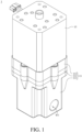
- FIG. 1 is a perspective view of a proportional valve in accordance with an embodiment of the disclosure
- FIG. 2 is an exploded view of the proportional valve in FIG. 1
- FIG. 3 is another exploded view of the proportional valve in FIG. 1 .
- the proportional valve 1 includes a casing 11 and a valve trim 12.
- the casing 11 includes a connecting seat 111, an accommodating seat 112 and a cover 113.
- the connecting seat 111 has two fluid inlets W1 and a fluid outlet W2.
- the shapes of the connecting seat 111 and the accommodating seat 112 are, for example, cup-shaped, and the accommodating seat 112 is slightly smaller than the connecting seat 111 in size.
- the accommodating seat 112 is stacked on the connecting seat 111, and a part of the accommodating seat 112 is surrounded by the connecting seat 111.
- the accommodating seat 112 has an accommodating space S.
- Each of two first connection passageways O1 and a second connection passageway O2 passes through the connecting seat 111 and the accommodating seat 112.
- the two first connection passageways O1 are respectively in fluid communication with the two fluid inlets W1.
- the second connection passageway O2 is in fluid communication with the fluid outlet W2.
- the accommodating space S is in fluid communication with the two first connection passageways O1 and the second connection passageway O2.
- the cover 113 covers the accommodating seat 112.
- the valve trim 12 is located in the accommodating space S of the casing 11.
- the valve trim 12 has a flow splitter 121 and an adjusting rotor 122.
- the flow splitter 121 has two third connection passageways O3 and a fourth connection passageway O4.
- Each of the third connection passageways O3 is, for example, in a form of plural through holes.
- the two third connection passageways O3 are in fluid communication with the two first connection passageways O1.
- the fourth connection passageway O4 is in fluid communication with the second connection passageway O2.
- the adjusting rotor 122 has a channel T and a blocking portion B.
- the channel T is in fluid communication with the two third connection passageways O3 and the fourth connection passageway O4.
- the blocking portion B corresponds to the two third connection passageways O3.
- the adjusting rotor 122 is rotatably disposed on the flow splitter 121 so that the blocking portion B blocks a part of the two third connection passageways O3 to adjust an overlapping area between the channel T and the two third connection passageways O3, or specifically, an overlapping area between the channel T and the through holes. Accordingly, fluid is able to flow into the casing 11 via the two fluid inlets W1 and then flow out from the casing 11 sequentially via the two first connection passageways O1, the two third connection passageways O3, the channel T, the fourth connection passageway O4, the second connection passageway O2 and the fluid outlet W2.
- the blocking portion B of the adjusting rotor 122 blocks part of the through holes of the two third connection passageways 03fluid, thereby controlling the flow amount of the fluid.
- the proportional valve 1 further includes an axial thrust bearing 16.
- the axial thrust bearing 16 is located in the accommodating space S of the casing 11 and stacked on a side of an adapter 13 away from the adjusting rotor 122.
- the axial thrust bearing 16 can bear the axial force applied on the proportional valve 1, so as to reduce the friction between the components of the proportional valve 1 during operation of the proportional valve 1.
- the proportional valve 1 further includes a shaft seal 17.
- the shaft seal 17 is located in the accommodating space S of the casing 11.
- the shaft seal 17 is sleeved on a shaft 14 and stacked on the side of the axial thrust bearing 16 away from the adjusting rotor 122. Accordingly, the fluid at the shaft 14 can be prevented from leaking out of the casing 11 by the arrangement of the shaft seal 17.
- the proportional valve 1 further includes a first seal 18.
- the first seal 18 is clamped between the cover 113 and the accommodating seat 112 and surrounds the accommodating space S. Accordingly, the first seal 18 can improve the sealing effect of the casing 11 and prevent the fluid from leaking out of the accommodating space S.
- the proportional valve 1 further includes a second seal 19 and a third seal 20.
- the second seal 19 is clamped between the connecting seat 111 and the accommodating seat 112 and surrounds the two first connection passageways O1 and the second connection passageway O2.
- the third seal 20 is clamped between the accommodating seat 112 and the flow splitter 121 and surrounds the two first connection passageways O1 and the second connection passageway O2. Accordingly, the second seal 19 and the third seal 20 can improve the sealing effect of the casing 11 and prevent the fluid from leaking out of the two first connection passageways O1 and the second connection passageway O2.
- FIG. 3 is another exploded view of the proportional valve in FIG. 1
- FIG. 4 is a partial and exploded view of the proportional valve in FIG. 1 .
- the proportional valve 1 further includes the adapter 13, the shaft 14 and a driver 15.
- the adapter 13 has three first engagement portions C1, and the three first engagement portions C1 are parts of the adapter 13 protruded outwardly.
- the adjusting rotor 122 has three second engagement portions C2, and the three second engagement portions C2 are parts of the adjusting rotor 122 recessed inwardly.
- the three first engagement portions C1 and the three second engagement portions C2 are matched in structure by one is a convex structure and the other one is a concave structure, and the three second engagement portions C2 are engaged with the three first engagement portions C1.
- the driver 15 includes an output shaft 151.
- the driver 15 is, for example, a motor.
- the output shaft 151 of the driver 15 is connected to the shaft 14, and the shaft 14 is connected to the adapter 13, so that the output shaft 151 of the driver 15 drives the adapter 13 to rotate via the shaft 14. Accordingly, with the engagement between the first engagement portions C1 of the adapter 13 and the second engagement portions C2 of the adjusting rotor 122 and the rotation of the adapter 13 driven by the driver 15, the adjusting rotor 122 can control the flow by blocking or not blocking the third connection passageways O3 of the flow splitter 121.
- the cover 113 of the proportional valve 1 further has two first limiting structures L1, and the two first limiting structures L1 are parts of the cover 113 recessed inwardly.
- the adapter 13 has two second limiting structures L2, and the two second limiting structures L2 are parts of the adapter 13 protruded outwardly.
- the two first limiting structures L1 are larger than the two second limiting structures L2 in size.
- the two second limiting structures L2 can be placed into the two first limiting structures L1, and the two second limiting structures L2 are rotatable relative to the two first limiting structures L1. Accordingly, the rotation range of the two second limiting structures L2 is limited within the two first limiting structures L1, so the rotation angle of the adapter 13 is also limited within the range of the two first limiting structures L1.
- FIG. 5 is a partial and cross-sectional view of the proportional valve in FIG. 1 when a valve trim thereof is in an open state
- FIG. 6 is a partial perspective view of the proportional valve in FIG. 5
- FIG. 7 is a bottom view of a flow splitter and an adjusting rotor of the proportional valve in FIG. 5 .
- the second limiting structures L2 of the adapter 13 are located on a side of the first limiting structures L1 of the cover 113, so that the blocking portion B of the adjusting rotor 122 does not block the two second third connection passageways O3 of the flow splitter 121. Therefore, the valve trim 12 of the proportional valve 1 is in the open state.
- the two fluid inlets W1, the two first connection passageways 01, the two third connection passageways O3, the fourth connection passageway O4, the second connection passageway O2 and the fluid outlet W2 can form a fluid passage in which fluid can smoothly flow.
- the fluid is able to flow into the casing 11 via the two fluid inlets W1 along the direction D, then flow into the channel T via the two first connection passageways O1 and the two third connection passageways O3 along the direction E, and then flow toward the fourth connection passageway O4 in the channel T along the direction F, then pass through the fourth connection passageway O4 along the direction G, and finally flow out of the casing 11 via the fluid outlet W2 along the direction H.
- FIG. 8 is a partial cross-sectional view of the proportional valve in FIG. 1 when a valve trim thereof is in a closed state
- FIG. 9 is a partial perspective view of the proportional valve in FIG. 8
- FIG. 10 is a bottom view of the flow splitter and the adjusting rotor of the proportional valve in FIG. 8 .
- the output shaft 151 of the driver 15 is connected to the shaft 14 for transmitting the driving force of the driver 15 to the adapter 13, so that the second limiting structures L2 of the adapter 13 rotate about an axis J by an angle, for example, 90 degrees, along the direction I within the limiting range of the first limiting structures L1 of the cover 113.
- the adapter 13 can drive the adjusting rotor 122 to rotate, so that the blocking portion B of the adjusting rotor 122 is rotated from the open state of the valve trim 12 of the proportional valve 1 to the closed state of the valve trim 12 of the proportional valve 1.
- the rotated blocking portion B blocks the two third connection passageways O3 of the flow splitter 121, and the blocking portion B blocks the fluid communication between the third connection passageways O3 and the channel T, so that after the fluid flows through the two fluid inlets W1 along the direction D and flows through the two first connection passageways O1 along the direction E, the fluid is blocked at the two third connection passageways O3 and cannot continue to flow.
- the proportional valve 1 can adjust the fluid flow via the adjusting rotor 122 and the flow splitter 121.
- the blocking portion B of the adjusting rotor 122 when the blocking portion B of the adjusting rotor 122 does not block the third connection passageways O3, the third connection passageways O3, the channel T and the fourth connection passageway O4 form a fluid passage, so that the fluid can flow there through.
- the blocking portion B of the adjusting rotor 122 blocks the third connection passageways O3, the blocking portion B blocks the fluid communication between the third connection passageway O3, the channel T and the fourth connection passageway O4, so that the fluid cannot flow there through.
- the two third connection passageways O3 are in a form of plural through holes, and several of the through holes is blocked by the adjusting rotor 122 for adjusting the flow amount there through.
- the present disclosure is not limited thereto.
- the two third connection passageways may be in a form of single through hole, and part of the through hole is blocked by the adjusting rotor 122 for adjusting the flow amount there through.
- the two fluid inlets W1 are respectively located on two opposite sides of the fluid outlet W2, but the present disclosure is not limited thereto. In some other embodiments, the two fluid inlets may be located on adjacent sides of the fluid outlet.
- each of the quantities of the fluid inlets W1, the first connection passageways O1, the third connection passageways O3 and the blocking portions B is two, but the present disclosure is not limited thereto. In some other embodiments, each of the quantities of the fluid inlets, the first connection passageways, the third connection passageways and the blocking portions may be one or more than two.
- each of the quantities of the fluid outlet W2, the second connection passageway O2 and the fourth connection passageway O4 is one, but the present disclosure is not limited thereto. In some other embodiments, each of the quantities of the fluid outlet, the second connection passageway and the fourth connection passageway may be more than one.
- the three first engagement portions C1 are parts of the adapter 13 protruded outwardly, and the three second engagement portions C2 are parts of the adjusting rotor 122 recessed inwardly, but the present disclosure is not limited thereto. In some other embodiments, the three first engagement portions may be parts of the adapter recessed inwardly, and the three second engagement portions may be parts of the adjusting rotor 122 protruded outwardly.
- each of the quantities of the first engagement portions C1 and the second engagement portions C2 is three, but the present disclosure is not limited thereto. In some other embodiments, each of the quantities of the first engagement portions and the second engagement portions may be one, two or more than three.
- each of the quantities of the first limiting structures L1 and the second limiting structures L2 is two, but the present disclosure is not limited thereto. In some other embodiments, each of the quantities of the first limiting structures and the second limiting structures may be one or more than two.
- the proportional valve adjusts the fluid flow via the flow splitter and the adjusting rotor thereof.
- the blocking portion of the adjusting rotor does not block the at least one third connection passageway, the at least one fluid inlet, the at least one first connection passageway, the at least one third connection passageway, the at least one fourth connection passageway, the at least one second connection passageway and the fluid outlet can form a fluid passage, such that the fluid can flow smoothly.
- the blocking portion of the adjusting rotor blocks the two third connection passageways, the blocking portion blocks the fluid communication between the third connection passageway and the channel, so that the fluid cannot flow through.
- the proportional valve as described above does not use the elastic force of the spring to control the opening degree of the valve trim, but controls the opening degree of the valve trim via the rotation angle of the flow splitter and the adjusting rotor. Therefore, the proportional valve as described above does not have the problems of spring elastic fatigue and reduced control accuracy, thereby greatly improving the lifespan of the proportional valve, and enabling the proportional valve to maintain high accuracy of fluid flow control after the proportional valve is used for many times.
Landscapes
- Engineering & Computer Science (AREA)
- General Engineering & Computer Science (AREA)
- Mechanical Engineering (AREA)
- Physics & Mathematics (AREA)
- Electromagnetism (AREA)
- Multiple-Way Valves (AREA)
- Fluid-Driven Valves (AREA)
- Magnetically Actuated Valves (AREA)
Applications Claiming Priority (1)
| Application Number | Priority Date | Filing Date | Title |
|---|---|---|---|
| TW111210566U TWM638533U (zh) | 2022-09-28 | 2022-09-28 | 比例閥 |
Publications (3)
| Publication Number | Publication Date |
|---|---|
| EP4345346A1 true EP4345346A1 (de) | 2024-04-03 |
| EP4345346C0 EP4345346C0 (de) | 2025-10-01 |
| EP4345346B1 EP4345346B1 (de) | 2025-10-01 |
Family
ID=85920402
Family Applications (1)
| Application Number | Title | Priority Date | Filing Date |
|---|---|---|---|
| EP23168927.4A Active EP4345346B1 (de) | 2022-09-28 | 2023-04-20 | Proportionalventil |
Country Status (4)
| Country | Link |
|---|---|
| US (1) | US12529430B2 (de) |
| EP (1) | EP4345346B1 (de) |
| CN (2) | CN117780959A (de) |
| TW (1) | TWM638533U (de) |
Families Citing this family (3)
| Publication number | Priority date | Publication date | Assignee | Title |
|---|---|---|---|---|
| JP7585948B2 (ja) * | 2021-04-21 | 2024-11-19 | 株式会社デンソー | バルブ装置 |
| CN120712427A (zh) * | 2024-01-18 | 2025-09-26 | 广东德昌电机有限公司 | 多通道阀门以及热管理系统 |
| WO2025205358A1 (ja) * | 2024-03-26 | 2025-10-02 | 株式会社デンソー | バルブ装置 |
Citations (6)
| Publication number | Priority date | Publication date | Assignee | Title |
|---|---|---|---|---|
| EP0063627A1 (de) * | 1981-04-28 | 1982-11-03 | Rosenthal Technik AG | Mischbatterie |
| US20030145889A1 (en) * | 2000-03-07 | 2003-08-07 | Francesco Knapp | Delivery control device for the supply to hydraulic apparatuses |
| DE4139815B4 (de) * | 1991-12-03 | 2005-11-24 | Grohe Water Technology Ag & Co. Kg | Umschaltventil |
| US20110120574A1 (en) * | 2009-05-20 | 2011-05-26 | Qiyue Chen | Intelligent thermostatic water outflowing device |
| US20160289931A1 (en) * | 2015-04-01 | 2016-10-06 | Hain Yo Enterprises Co., Ltd. | Fine ceramic valve for faucets |
| US20170108127A1 (en) * | 2015-10-14 | 2017-04-20 | Hain Yo Enterprises Co., Ltd. | Ceramic control valve for switching between multiple water sources |
Family Cites Families (46)
| Publication number | Priority date | Publication date | Assignee | Title |
|---|---|---|---|---|
| US3756275A (en) * | 1972-01-26 | 1973-09-04 | Wilkes Pool Corp | Adapter for a valve and tank assembly |
| US4383234A (en) * | 1981-10-14 | 1983-05-10 | The Singer Company | Magnetic latch valve |
| US5398717A (en) * | 1994-04-15 | 1995-03-21 | Kohler Co. | Fluid valve |
| US5741005A (en) * | 1996-03-15 | 1998-04-21 | Fleck Controls, Inc. | Rotary disk control valve for a water conditioning system |
| AUPO902797A0 (en) * | 1997-09-05 | 1997-10-02 | Cortronix Pty Ltd | A rotary blood pump with hydrodynamically suspended impeller |
| IT1314504B1 (it) * | 2000-03-02 | 2002-12-18 | Cozzani Mario S R L | Valvola per il controllo di flussi di grande sezione, in particolareper compressori o simili. |
| KR100426709B1 (ko) * | 2000-06-05 | 2004-04-14 | 가부시키가이샤 후지킨 | 오리피스 내장밸브 |
| DE10046679A1 (de) * | 2000-09-21 | 2002-04-11 | Hansgrohe Ag | Kartusche für eine Sanitärarmatur |
| JP4244703B2 (ja) * | 2003-05-26 | 2009-03-25 | パナソニック株式会社 | 冷却装置 |
| WO2005088210A1 (en) * | 2004-03-08 | 2005-09-22 | Sumitomo Heavy Industries, Ltd. | Wearless valve for cryorefrigerator |
| US20070068583A1 (en) * | 2005-09-27 | 2007-03-29 | Johnson Dwight N | Motor-driven hydraulic valve cartridge |
| JP2009532131A (ja) * | 2006-03-31 | 2009-09-10 | オーキス メディカル コーポレイション | 回転血液ポンプ |
| GB0618837D0 (en) * | 2006-09-25 | 2006-11-01 | Wavefront Energy & Environment | Rapid opening valve for use in boreholes |
| ES2334317B1 (es) * | 2008-09-05 | 2010-10-15 | Valvules I Racords Canovelles, S.A. | "dispositivo para la distribucion controlada de liquidos". |
| EP2187104B1 (de) * | 2008-11-18 | 2011-12-21 | Sauer-Danfoss ApS | Flüssigkeitsverteilungsventil |
| US8074678B2 (en) * | 2009-05-27 | 2011-12-13 | Emerson Electric Co. | Reversible flow valve assembly |
| AT511185B1 (de) * | 2011-03-02 | 2013-10-15 | Argos Zyklotron Betr S Gesmbh | Ventil und verwendung des ventils |
| US9765683B2 (en) * | 2012-01-18 | 2017-09-19 | International Engine Intellectual Property Company, Llc. | Modular water pump |
| US8857469B2 (en) * | 2012-10-11 | 2014-10-14 | Geann Industrial Co., Ltd. | Water valve suitable for use with a bathtub |
| DE202012012980U1 (de) * | 2012-11-07 | 2014-06-18 | Mack & Schneider Gmbh | Ventileinrichtung |
| DE202012012978U1 (de) * | 2012-11-07 | 2014-06-16 | Mack & Schneider Gmbh | Scheibenventil |
| DE202012012981U1 (de) * | 2012-11-07 | 2014-06-18 | Mack & Schneider Gmbh | Scheibenventil |
| JP5686827B2 (ja) * | 2013-01-23 | 2015-03-18 | 株式会社鷺宮製作所 | 遠心ポンプ |
| JP5830492B2 (ja) * | 2013-05-24 | 2015-12-09 | 株式会社日本自動車部品総合研究所 | 高圧ポンプ |
| CN104235070A (zh) * | 2013-06-13 | 2014-12-24 | 德昌电机(深圳)有限公司 | 泵壳及具有该泵壳的泵 |
| EP3071277B1 (de) * | 2013-11-20 | 2018-03-28 | Fluid Automation Systems S.A. | Exspirationsventil zur steuerung eines flusses |
| SG11201606138WA (en) * | 2014-02-04 | 2016-08-30 | Carrier Corp | Hard interface dynamic seals |
| DE102015210241A1 (de) * | 2014-06-05 | 2015-12-17 | Schaeffler Technologies AG & Co. KG | Drehventil mit einem isolierenden Verteilungskörper |
| EP3167211B1 (de) * | 2014-07-10 | 2018-01-03 | Fluid Automation Systems S.A. | Ventil mit verdoppelter öffnung und variablen durchfluss |
| JP6166301B2 (ja) * | 2014-07-22 | 2017-07-19 | 株式会社鷺宮製作所 | 遠心ポンプ |
| GB2530524A (en) * | 2014-09-24 | 2016-03-30 | Kohler Mira Ltd | Fluid Control Valves |
| DE102014221180A1 (de) * | 2014-10-17 | 2016-04-21 | Mack & Schneider Gmbh | Ventileinrichtung |
| SE1500180A1 (sv) * | 2015-04-14 | 2016-10-04 | Staccato Tech Ab | Valve Seat |
| US10344877B2 (en) * | 2015-12-01 | 2019-07-09 | Tesla Motors, Inc. | Multi-port valve with multiple operation modes |
| EP3486536B1 (de) * | 2016-07-12 | 2021-08-25 | Zhejiang Sanhua Intelligent Controls Co., Ltd. | Durchflussregler |
| SG10201605723YA (en) * | 2016-07-13 | 2018-02-27 | Delta Electronics Intl Singapore Pte Ltd | Integrated Fluidic Module |
| DE102018127147A1 (de) * | 2017-11-06 | 2019-05-09 | Aisin Seiki Kabushiki Kaisha | Strömungswegumschaltventil und Reinigungsvorrichtung |
| JP2019183773A (ja) * | 2018-04-13 | 2019-10-24 | アイシン精機株式会社 | 電動ポンプ |
| EP3569904B1 (de) * | 2018-05-18 | 2020-11-04 | Fas Medic S.A. | Ventilanordnung |
| GB201808925D0 (en) * | 2018-05-31 | 2018-07-18 | Johnson Electric Sa | Multi-channel disc valve assembly |
| EP3667087B1 (de) * | 2018-12-13 | 2022-12-07 | Grundfos Holding A/S | Pumpenanordnung |
| EP3667092B1 (de) * | 2018-12-13 | 2021-08-18 | Grundfos Holding A/S | Pumpenanordnung |
| US20200362973A1 (en) * | 2019-05-14 | 2020-11-19 | Tecan Trading Ag | Non-sticking rotary valve |
| US10914390B2 (en) * | 2019-06-06 | 2021-02-09 | Robert Bosch Llc | Fluid valve assembly including valve body with seal retention features |
| US11994221B2 (en) * | 2021-06-01 | 2024-05-28 | Chia-Po Chang | Water control valve |
| US11572957B2 (en) * | 2021-06-08 | 2023-02-07 | Robert Bosch Gmbh | Rotary disc valve |
-
2022
- 2022-09-28 TW TW111210566U patent/TWM638533U/zh unknown
- 2022-11-03 US US17/980,483 patent/US12529430B2/en active Active
- 2022-11-11 CN CN202211412895.0A patent/CN117780959A/zh active Pending
- 2022-11-11 CN CN202223005603.XU patent/CN218863306U/zh active Active
-
2023
- 2023-04-20 EP EP23168927.4A patent/EP4345346B1/de active Active
Patent Citations (6)
| Publication number | Priority date | Publication date | Assignee | Title |
|---|---|---|---|---|
| EP0063627A1 (de) * | 1981-04-28 | 1982-11-03 | Rosenthal Technik AG | Mischbatterie |
| DE4139815B4 (de) * | 1991-12-03 | 2005-11-24 | Grohe Water Technology Ag & Co. Kg | Umschaltventil |
| US20030145889A1 (en) * | 2000-03-07 | 2003-08-07 | Francesco Knapp | Delivery control device for the supply to hydraulic apparatuses |
| US20110120574A1 (en) * | 2009-05-20 | 2011-05-26 | Qiyue Chen | Intelligent thermostatic water outflowing device |
| US20160289931A1 (en) * | 2015-04-01 | 2016-10-06 | Hain Yo Enterprises Co., Ltd. | Fine ceramic valve for faucets |
| US20170108127A1 (en) * | 2015-10-14 | 2017-04-20 | Hain Yo Enterprises Co., Ltd. | Ceramic control valve for switching between multiple water sources |
Also Published As
| Publication number | Publication date |
|---|---|
| US12529430B2 (en) | 2026-01-20 |
| TWM638533U (zh) | 2023-03-11 |
| CN117780959A (zh) | 2024-03-29 |
| EP4345346C0 (de) | 2025-10-01 |
| US20240102561A1 (en) | 2024-03-28 |
| EP4345346B1 (de) | 2025-10-01 |
| CN218863306U (zh) | 2023-04-14 |
Similar Documents
| Publication | Publication Date | Title |
|---|---|---|
| EP4345346A1 (de) | Proportionalventil | |
| KR102252705B1 (ko) | 밸브 장치 | |
| US12359740B2 (en) | Valve device | |
| US11454330B1 (en) | Multi-level rotary plug valve | |
| US20150075453A1 (en) | Rotary valve | |
| US20240001731A1 (en) | Multi-Port Rotary Valve | |
| US20190162314A1 (en) | Valve device | |
| US12523306B2 (en) | Valve device | |
| US11255449B2 (en) | Valve device | |
| US9976654B2 (en) | Valve device | |
| US12135095B2 (en) | Valve device | |
| US12078252B2 (en) | Multi-port rotary valve | |
| US12276343B2 (en) | Multi-port rotary valve | |
| US20240003429A1 (en) | Valve device | |
| JP2020051547A (ja) | バルブ装置 | |
| CN114909485B (zh) | 阀 | |
| CN120777380A (zh) | 旋转盘阀 | |
| US12345348B2 (en) | Valve device | |
| US12338906B2 (en) | Valve device | |
| US10788143B2 (en) | Cam actuated coolant control valve | |
| CN116964364A (zh) | 阀装置 | |
| CN223191053U (zh) | 一种阀装置 | |
| US20250314314A1 (en) | Rotary Disc Valve | |
| CN100363670C (zh) | 步进电机驱动阀 | |
| CN119084590A (zh) | 蝶阀及飞行器 |
Legal Events
| Date | Code | Title | Description |
|---|---|---|---|
| PUAI | Public reference made under article 153(3) epc to a published international application that has entered the european phase |
Free format text: ORIGINAL CODE: 0009012 |
|
| STAA | Information on the status of an ep patent application or granted ep patent |
Free format text: STATUS: THE APPLICATION HAS BEEN PUBLISHED |
|
| AK | Designated contracting states |
Kind code of ref document: A1 Designated state(s): AL AT BE BG CH CY CZ DE DK EE ES FI FR GB GR HR HU IE IS IT LI LT LU LV MC ME MK MT NL NO PL PT RO RS SE SI SK SM TR |
|
| STAA | Information on the status of an ep patent application or granted ep patent |
Free format text: STATUS: REQUEST FOR EXAMINATION WAS MADE |
|
| 17P | Request for examination filed |
Effective date: 20240716 |
|
| RBV | Designated contracting states (corrected) |
Designated state(s): AL AT BE BG CH CY CZ DE DK EE ES FI FR GB GR HR HU IE IS IT LI LT LU LV MC ME MK MT NL NO PL PT RO RS SE SI SK SM TR |
|
| GRAP | Despatch of communication of intention to grant a patent |
Free format text: ORIGINAL CODE: EPIDOSNIGR1 |
|
| STAA | Information on the status of an ep patent application or granted ep patent |
Free format text: STATUS: GRANT OF PATENT IS INTENDED |
|
| RIC1 | Information provided on ipc code assigned before grant |
Ipc: F16K 3/04 20060101ALI20250528BHEP Ipc: F16K 27/04 20060101ALI20250528BHEP Ipc: F16K 11/074 20060101AFI20250528BHEP |
|
| INTG | Intention to grant announced |
Effective date: 20250618 |
|
| GRAS | Grant fee paid |
Free format text: ORIGINAL CODE: EPIDOSNIGR3 |
|
| GRAA | (expected) grant |
Free format text: ORIGINAL CODE: 0009210 |
|
| STAA | Information on the status of an ep patent application or granted ep patent |
Free format text: STATUS: THE PATENT HAS BEEN GRANTED |
|
| AK | Designated contracting states |
Kind code of ref document: B1 Designated state(s): AL AT BE BG CH CY CZ DE DK EE ES FI FR GB GR HR HU IE IS IT LI LT LU LV MC ME MK MT NL NO PL PT RO RS SE SI SK SM TR |
|
| REG | Reference to a national code |
Ref country code: GB Ref legal event code: FG4D Ref country code: CH Ref legal event code: F10 Free format text: ST27 STATUS EVENT CODE: U-0-0-F10-F00 (AS PROVIDED BY THE NATIONAL OFFICE) Effective date: 20251001 |
|
| REG | Reference to a national code |
Ref country code: DE Ref legal event code: R096 Ref document number: 602023007039 Country of ref document: DE |
|
| REG | Reference to a national code |
Ref country code: IE Ref legal event code: FG4D |
|
| U01 | Request for unitary effect filed |
Effective date: 20251008 |
|
| U07 | Unitary effect registered |
Designated state(s): AT BE BG DE DK EE FI FR IT LT LU LV MT NL PT RO SE SI Effective date: 20251015 |
|
| PG25 | Lapsed in a contracting state [announced via postgrant information from national office to epo] |
Ref country code: ES Free format text: LAPSE BECAUSE OF FAILURE TO SUBMIT A TRANSLATION OF THE DESCRIPTION OR TO PAY THE FEE WITHIN THE PRESCRIBED TIME-LIMIT Effective date: 20251001 |
|
| PG25 | Lapsed in a contracting state [announced via postgrant information from national office to epo] |
Ref country code: NO Free format text: LAPSE BECAUSE OF FAILURE TO SUBMIT A TRANSLATION OF THE DESCRIPTION OR TO PAY THE FEE WITHIN THE PRESCRIBED TIME-LIMIT Effective date: 20260101 |
|
| PG25 | Lapsed in a contracting state [announced via postgrant information from national office to epo] |
Ref country code: HR Free format text: LAPSE BECAUSE OF FAILURE TO SUBMIT A TRANSLATION OF THE DESCRIPTION OR TO PAY THE FEE WITHIN THE PRESCRIBED TIME-LIMIT Effective date: 20251001 |
|
| U20 | Renewal fee for the european patent with unitary effect paid |
Year of fee payment: 4 Effective date: 20260312 |
|
| PG25 | Lapsed in a contracting state [announced via postgrant information from national office to epo] |
Ref country code: RS Free format text: LAPSE BECAUSE OF FAILURE TO SUBMIT A TRANSLATION OF THE DESCRIPTION OR TO PAY THE FEE WITHIN THE PRESCRIBED TIME-LIMIT Effective date: 20260101 |
|
| PG25 | Lapsed in a contracting state [announced via postgrant information from national office to epo] |
Ref country code: IS Free format text: LAPSE BECAUSE OF FAILURE TO SUBMIT A TRANSLATION OF THE DESCRIPTION OR TO PAY THE FEE WITHIN THE PRESCRIBED TIME-LIMIT Effective date: 20260201 |