EP4346051A1 - Convertisseur de puissance cc-ca électronique intelligent à sources d'énergie multiples - Google Patents
Convertisseur de puissance cc-ca électronique intelligent à sources d'énergie multiples Download PDFInfo
- Publication number
- EP4346051A1 EP4346051A1 EP23386012.1A EP23386012A EP4346051A1 EP 4346051 A1 EP4346051 A1 EP 4346051A1 EP 23386012 A EP23386012 A EP 23386012A EP 4346051 A1 EP4346051 A1 EP 4346051A1
- Authority
- EP
- European Patent Office
- Prior art keywords
- power electronic
- power
- converter
- local
- electronic converter
- Prior art date
- Legal status (The legal status is an assumption and is not a legal conclusion. Google has not performed a legal analysis and makes no representation as to the accuracy of the status listed.)
- Pending
Links
Images
Classifications
-
- H—ELECTRICITY
- H02—GENERATION; CONVERSION OR DISTRIBUTION OF ELECTRIC POWER
- H02M—APPARATUS FOR CONVERSION BETWEEN AC AND AC, BETWEEN AC AND DC, OR BETWEEN DC AND DC, AND FOR USE WITH MAINS OR SIMILAR POWER SUPPLY SYSTEMS; CONVERSION OF DC OR AC INPUT POWER INTO SURGE OUTPUT POWER; CONTROL OR REGULATION THEREOF
- H02M7/00—Conversion of AC power input into DC power output; Conversion of DC power input into AC power output
-
- H—ELECTRICITY
- H02—GENERATION; CONVERSION OR DISTRIBUTION OF ELECTRIC POWER
- H02J—ELECTRIC POWER NETWORKS; CIRCUIT ARRANGEMENTS OR SYSTEMS FOR SUPPLYING OR DISTRIBUTING ELECTRIC POWER; SYSTEMS FOR STORING ELECTRIC ENERGY
- H02J3/00—Circuit arrangements for AC mains or AC distribution networks
- H02J3/38—Arrangements for feeding a single network from two or more generators or sources in parallel; Arrangements for feeding already energised networks from additional generators or sources in parallel
- H02J3/381—Dispersed generators
-
- H—ELECTRICITY
- H01—ELECTRIC ELEMENTS
- H01G—CAPACITORS; CAPACITORS, RECTIFIERS, DETECTORS, SWITCHING DEVICES, LIGHT-SENSITIVE OR TEMPERATURE-SENSITIVE DEVICES OF THE ELECTROLYTIC TYPE
- H01G11/00—Hybrid capacitors, i.e. capacitors having different positive and negative electrodes; Electric double-layer [EDL] capacitors; Processes for the manufacture thereof or of parts thereof
- H01G11/08—Structural combinations, e.g. assembly or connection, of hybrid or EDL capacitors with other electric components, at least one hybrid or EDL capacitor being the main component
-
- H—ELECTRICITY
- H02—GENERATION; CONVERSION OR DISTRIBUTION OF ELECTRIC POWER
- H02J—ELECTRIC POWER NETWORKS; CIRCUIT ARRANGEMENTS OR SYSTEMS FOR SUPPLYING OR DISTRIBUTING ELECTRIC POWER; SYSTEMS FOR STORING ELECTRIC ENERGY
- H02J3/00—Circuit arrangements for AC mains or AC distribution networks
- H02J3/28—Arrangements for balancing of the load in networks by storage of energy
- H02J3/32—Arrangements for balancing of the load in networks by storage of energy using batteries or super capacitors with converting means
- H02J3/322—Arrangements for balancing of the load in networks by storage of energy using batteries or super capacitors with converting means the battery being on-board an electric or hybrid vehicle, e.g. vehicle to grid arrangements [V2G], power aggregation, use of the battery for network load balancing, coordinated or cooperative battery charging
-
- Y—GENERAL TAGGING OF NEW TECHNOLOGICAL DEVELOPMENTS; GENERAL TAGGING OF CROSS-SECTIONAL TECHNOLOGIES SPANNING OVER SEVERAL SECTIONS OF THE IPC; TECHNICAL SUBJECTS COVERED BY FORMER USPC CROSS-REFERENCE ART COLLECTIONS [XRACs] AND DIGESTS
- Y02—TECHNOLOGIES OR APPLICATIONS FOR MITIGATION OR ADAPTATION AGAINST CLIMATE CHANGE
- Y02E—REDUCTION OF GREENHOUSE GAS [GHG] EMISSIONS, RELATED TO ENERGY GENERATION, TRANSMISSION OR DISTRIBUTION
- Y02E10/00—Energy generation through renewable energy sources
- Y02E10/50—Photovoltaic [PV] energy
- Y02E10/56—Power conversion systems, e.g. maximum power point trackers
Definitions
- the invention refers to a direct current to alternating current (DC/AC) power electronic converter with multiple DC energy sources and an AC output, whose power electronic circuit is of transformerless multiple-port converter topology (Multi-Port Converter, MPC) interconnecting a hybrid energy storage system, a photovoltaic (PV) array, an AC local electrical load and the electric grid.
- DC/AC direct current to alternating current
- MPC transformerless multiple-port converter topology
- DC/AC power electronic converters are required to interface Renewable Energy Sources (RES) and energy storage systems with the electric grid.
- RES Renewable Energy Sources
- power electronic converters have been developed for PV systems with the ability to support the local distribution network voltage and frequency, which remains limited due to the absence of energy storage.
- the effectiveness of voltage regulation in distribution systems to which high-power RES systems are connected has been investigated through the interconnection of separate energy storage systems.
- the energy storage system can be based either on batteries that have the advantage of high energy density, or supercapacitors that have the advantage of higher power density, or hybrid devices that combine the advantages of these two types of energy storage.
- hybrid energy storage in PV systems has been performed by combining separate individual direct current to direct current (DC/DC) power electronic converters for each energy storage unit, resulting in increased complexity and cost.
- DC/DC direct current to direct current
- the multiple-input power converters of MPC topology offer a solution, but their application has been limited to energy storage integration devices in PV systems using only batteries and not hybrid storage systems.
- the currently available on the market hybrid PV inverters have only batteries as an energy storage unit and do not offer grid support functions. Also, inverters with the ability to connect only batteries and without the ability to connect supercapacitors and PV arrays and grid-support capability are currently available on the market.
- the survey of commercially available power electronic converters and related scientific literature highlights the need to develop the smart power electronic converter (1) of the present invention, which compared to the DC/AC power converters developed at the research and industrial level has the following combined advantages: (a) interconnects a PV array, hybrid energy storage system, local electrical load and the electrical network to provide integrated services to them and (b) has integrated energy management subsystems, communication with the required entities of the electric power system (e.g. load aggregators and electricity provider) and forecasting algorithms for the served local AC load and the integrated PV power generation.
- the required entities of the electric power system e.g. load aggregators and electricity provider
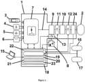
- the internal arrangement of the smart power electronic converter (1) of the present invention and its interconnection with the electrical network (2) is shown in Figure 1 . It contains four DC inputs for connecting an electric vehicle battery (3), a supercapacitor array (4), a battery array (5) and a PV array (6).
- One input (4) is reserved for the connection of supercapacitors as they are characterized by high power density (1-100 kW/kg), low thermal losses and long life that make them suitable for providing auxiliary services to electrical networks, such as support of the frequency and voltage (during normal disturbances and major disturbances) and short-period power supply to the local residential electric system (8).
- the four DC inputs (3), (4), (5) and (6) of the smart power electronic converter of the present invention are connected to the unique power electronic circuit (7) based on MPC transformerless topology, which does not use a separate power circuit in each of its DC power sources, in order to minimize the manufacturing cost and size and maximize the efficiency of the smart power electronic converter (1) of the present invention.
- the power electronic circuit (7) of the smart power electronic converter (1) of the present invention is connected to the electrical network (2) and the AC electrical load of the local electrical installation (8) through the electrical filters (9) and (10) of Figure 1 , respectively. It uses three automatic switches (11), (12) and (13) whose operating states (open/closed) determine if the local AC load (8) is electrified from the electrical network (2) or the smart electronic converter (1).
- the AC output (14) of the power electronic circuit (7) of the smart power electronic converter (1) of the present invention can be either single-phase or three-phase.
- the smart power electronic converter (1) of the present invention has a communication subsystem (20) with a local computer (15) for its parameterization by the user and supervision of its operation. It also allows the user to select the desired function without requiring modification of the hardware. Moreover, it has the ability to send signals and receive command-signals from the local network operator and/or the electric load aggregator (ELA) (16). In order to optimally charge the battery of the electric vehicle, it has the ability to communicate with the provider of electric mobility services (PEMS), the electric mobility transactions provider (EMTP) and the electricity provider (17).
- PEMS electric mobility services
- EMTP electric mobility transactions provider
- the smart power electronic converter (1) of the present invention has an automatic operation mode selection according to the connected storage units. For example, it has recognition of the connection of an electric vehicle and the ability to calculate the optimal charging and discharging times of its battery while simultaneously providing auxiliary services to the electric grid.
- the control unit (18) of the power electronic circuit (7) of the smart power electronic converter (1) of the present invention controls the DC inputs (3), (4), (5) and (6) of the converter in a unified manner in real time and calculates the optimal operating times of the interconnected residential AC load (8) and charging and discharging of the connected energy storage units (3) and (5), taking into account the values of the following parameters:
- the values of parameters 1 and 2 are obtained from the electrical network/system operator through a communication subsystem capable of sending signals and receiving command-signals (19).
- the values of parameters 3 and 4 are calculated by the optimization subsystem (21) of the smart power electronic converter of the present invention.
- the values of parameters 5 and 6 are entered by the user through the communication subsystem (20) with a local computer (15).
- the optimization subsystem (21) of the smart power electronic converter of the present invention calculates the minimum operating cost of the local system, satisfying all technical and operational constraints (e.g. maximum-minimum stored energy and power exchanged with the electric grid, etc.) and ensuring at the same time the maximization of the lifetime of the batteries (of the electric vehicle and the separate battery bank).
- the optimal charge-discharge trajectories of the electric vehicle battery, the battery bank and the power consumption of the flexible residential AC loads are obtained.
- Optimal operation scheduling is repeated at regular intervals to limit prediction errors and disturbances as much as possible using updated data from the DC inputs (3), (4), (5) and (6) and the communication subsystems (19) and (20).
- the use of conventional batteries gives the smart power electronic converter (1) of the present invention the additional capability of the optimal management of the energy it exchanges with the electrical network (2) depending on the load of the electrical network or the electricity price (e.g. variable or bi-zonal tariff).
- the electric vehicle connection (3) ensures the same characteristics as the previous case with the additional limitations resulting from the preferences of the electric vehicle user.
- the PV array connection (6) combined with the hybrid energy storage system consisting of units (3), (4) and (5), converts the local system (3), (4), (5), (6), (8) to a flexible producer-consumer of electricity.
- the real-time control subsystem of the smart power converter (22) implements the optimal charge-discharge trajectories of the electric vehicle battery (3) and the separate battery bank (5) as obtained by the optimization subsystem (21) by appropriately controlling the power electronic circuit (7) of the smart power electronic converter (1).
- the current state of charge of the storage units is estimated using measurements and after being compared to its optimal value then the power electronic circuit (7) imposes the necessary output power of the energy storage units to converge to the optimal trajectories.
- the power produced by the PV array (6) is maximized by controlling the power electronic circuit (7) of the smart power electronic converter (1) of the present invention by the Maximum Power Point Tracking (MPPT) unit (23) of the control unit (18) of the smart power inverter (1) so that the power produced by the PV array is continuously maximized, even in partially shading conditions that are often met in buildings.
- MPPT Maximum Power Point Tracking
- the smart power electronic converter of the present invention (1) has an electronic measuring device (24) of the instantaneous voltage and instantaneous current at the point of connection to the electrical network (2) on the basis of which the active and reactive power are calculated by the optimization subsystem (22) of the control unit (18).
- the optimization subsystem (22) of the control unit (18) Through the application of voltage-frequency droop control by the optimization subsystem (22) of the control unit (18), the voltage and frequency of the electrical network is supported.
- the energy of the supercapacitors is used for primary frequency support while the energy of the battery pack and the battery of the electric vehicle are used for secondary frequency support.
- the supercapacitors are fully charged during periods of normal frequency values and inject the necessary amount of energy for primary regulation during periods of under-frequency. In periods of over-frequency the frequency is supported by the battery array and the electric vehicle.
- the measurements of the electronic device (24) are also used by the control unit (18) to detect large voltage drops (transient or not).
- transient under-voltage phenomena the capability of uninterrupted operation is activated where the inverter provides the maximum possible reactive power to the electric grid and disconnects from it only when the voltage dip violates the limits imposed by the grid operator.
- non-transient phenomena e.g. detection of a power outage from the electrical network
- the switch (11) of Figure 1 is commanded to open and the control unit (18) of the smart power electronic converter controls its operation so that it supplies the residential AC load with constant voltage and frequency.
- the smart power electronic converter of the present invention was analyzed theoretically and its operation was confirmed through laboratory experiments. It has been shown that the smart power electronic converter (1) can interconnect a hybrid energy storage system consisting of modules (3), (4) and (5), a PV array (6), a local electrical AC load (8) and the electric grid (2), turning the local electrical system (3), (4), (5), (6), (8) into a flexible producer-consumer of electricity and providing voltage and frequency support services to the electric grid (2).
Landscapes
- Engineering & Computer Science (AREA)
- Power Engineering (AREA)
- Microelectronics & Electronic Packaging (AREA)
- Supply And Distribution Of Alternating Current (AREA)
- Direct Current Feeding And Distribution (AREA)
Applications Claiming Priority (1)
| Application Number | Priority Date | Filing Date | Title |
|---|---|---|---|
| GR20220100557A GR1010381B (el) | 2022-07-13 | 2022-07-13 | Εξυπνος ηλεκτρονικος μετατροπεας ισχυος συνεχους τασης σε εναλλασσομενη πολλαπλων πηγων ενεργειας |
Publications (1)
| Publication Number | Publication Date |
|---|---|
| EP4346051A1 true EP4346051A1 (fr) | 2024-04-03 |
Family
ID=85511203
Family Applications (1)
| Application Number | Title | Priority Date | Filing Date |
|---|---|---|---|
| EP23386012.1A Pending EP4346051A1 (fr) | 2022-07-13 | 2023-02-09 | Convertisseur de puissance cc-ca électronique intelligent à sources d'énergie multiples |
Country Status (2)
| Country | Link |
|---|---|
| EP (1) | EP4346051A1 (fr) |
| GR (1) | GR1010381B (fr) |
Families Citing this family (1)
| Publication number | Priority date | Publication date | Assignee | Title |
|---|---|---|---|---|
| CN116031920B (zh) * | 2023-02-14 | 2025-07-25 | 安徽大学 | 一种多端口电力电子设备的分层能量协调控制策略 |
Citations (4)
| Publication number | Priority date | Publication date | Assignee | Title |
|---|---|---|---|---|
| WO2005046033A2 (fr) * | 2003-10-29 | 2005-05-19 | The Board Of Trustees Of The University Of Illinois | Convertisseur de puissance cc-cc a entrees multiples |
| CN203761117U (zh) * | 2014-02-18 | 2014-08-06 | 西安理工大学 | 一种带软开关的多端口非隔离双向直流变换拓扑电路 |
| CN110350814A (zh) * | 2019-07-26 | 2019-10-18 | 浙江大学 | 一种控制三相多端口变流器中各个直流端口功率的矢量控制方法 |
| WO2021133718A1 (fr) * | 2019-12-23 | 2021-07-01 | Marquette University | Convertisseur de puissance multiport |
Family Cites Families (1)
| Publication number | Priority date | Publication date | Assignee | Title |
|---|---|---|---|---|
| US7772716B2 (en) * | 2007-03-27 | 2010-08-10 | Newdoll Enterprises Llc | Distributed maximum power point tracking system, structure and process |
-
2022
- 2022-07-13 GR GR20220100557A patent/GR1010381B/el active IP Right Grant
-
2023
- 2023-02-09 EP EP23386012.1A patent/EP4346051A1/fr active Pending
Patent Citations (4)
| Publication number | Priority date | Publication date | Assignee | Title |
|---|---|---|---|---|
| WO2005046033A2 (fr) * | 2003-10-29 | 2005-05-19 | The Board Of Trustees Of The University Of Illinois | Convertisseur de puissance cc-cc a entrees multiples |
| CN203761117U (zh) * | 2014-02-18 | 2014-08-06 | 西安理工大学 | 一种带软开关的多端口非隔离双向直流变换拓扑电路 |
| CN110350814A (zh) * | 2019-07-26 | 2019-10-18 | 浙江大学 | 一种控制三相多端口变流器中各个直流端口功率的矢量控制方法 |
| WO2021133718A1 (fr) * | 2019-12-23 | 2021-07-01 | Marquette University | Convertisseur de puissance multiport |
Non-Patent Citations (5)
| Title |
|---|
| ELMAKAWI ABDELSALAM M ET AL: "Non-isolated Multi-Port Inverter Topologies for Renewable Energy Applications: A review", 2019 1ST GLOBAL POWER, ENERGY AND COMMUNICATION CONFERENCE (GPECOM), IEEE, 12 June 2019 (2019-06-12), pages 321 - 330, XP033584683, DOI: 10.1109/GPECOM.2019.8778512 * |
| GANGASHETTY PREETI A ET AL: "Multi-port Converter Topology for Simultaneous Power Conversion of Buck/Boost and Inversion operation", 2022 3RD INTERNATIONAL CONFERENCE FOR EMERGING TECHNOLOGY (INCET), IEEE, 27 May 2022 (2022-05-27), pages 1 - 6, XP034149660, DOI: 10.1109/INCET54531.2022.9823992 * |
| N/A ?: "Erzeuger, Speicher und Verbraucher im Haushalt optimal vernetzt und gesteuert", 12 August 2021 (2021-08-12), Moosburg, Bavaria, pages 1 - 4, XP093118229, Retrieved from the Internet <URL:https://oxomi.com/portals/api/v1/documents/download?portal=3000812&user=&roles=&accessToken=&catalog=10339302> [retrieved on 20240111] * |
| RITURAJ GAUTAM ET AL: "A Comprehensive Review on Off-Grid and Hybrid Charging Systems for Electric Vehicles", IEEE OPEN JOURNAL OF THE INDUSTRIAL ELECTRONICS SOCIETY, IEEE, vol. 3, 19 April 2022 (2022-04-19), pages 203 - 222, XP011907164, DOI: 10.1109/OJIES.2022.3167948 * |
| TIAN QINGXIN ET AL: "Topology Synthesis of a Family of Integrated Three-Port Converters for Renewable Energy System Applications", IEEE TRANSACTIONS ON INDUSTRIAL ELECTRONICS, IEEE SERVICE CENTER, PISCATAWAY, NJ, USA, vol. 68, no. 7, 20 May 2020 (2020-05-20), pages 5833 - 5846, XP011845038, ISSN: 0278-0046, [retrieved on 20210323], DOI: 10.1109/TIE.2020.2994864 * |
Also Published As
| Publication number | Publication date |
|---|---|
| GR1010381B (el) | 2023-01-17 |
Similar Documents
| Publication | Publication Date | Title |
|---|---|---|
| US10756546B2 (en) | Methods of advanced grid and microgrid support functionalities through hybrid fuel cell systems | |
| AU2020242485B2 (en) | EV charger with adaptable charging protocol | |
| CN102104257B (zh) | 公寓楼的储能系统、集成电力管理系统及系统控制方法 | |
| Rahman et al. | Coordinated control of three-phase AC and DC type EV–ESSs for efficient hybrid microgrid operations | |
| US20170098950A1 (en) | Energy Systems and Energy Supply Methods | |
| CN103683272B (zh) | 一种独立直流微电网系统及其能量平衡控制方法 | |
| CN114465291A (zh) | 基于能源云互联的大型分布式柔性风光储充放市电交直流混用系统及控制系统 | |
| CN102420428A (zh) | 一种用于对微网能量进行管理的方法及系统 | |
| US20220263311A1 (en) | System and Method for Managing Power | |
| Kumar et al. | A review on microgrids with distributed energy resources | |
| CN111628516A (zh) | 低压台区负荷调节系统及调节方法 | |
| Onar et al. | Modeling, controls, and applications of community energy storage systems with used EV/PHEV batteries | |
| Shavolkin et al. | Improvement of the multifunctional converter of the photoelectric system with a storage battery for a local object with connection to a grid | |
| EP4346051A1 (fr) | Convertisseur de puissance cc-ca électronique intelligent à sources d'énergie multiples | |
| Falvo et al. | A flexible customer power device for energy management in a real smart micro-grid | |
| Zhao et al. | The hierarchical energy management control for residential energy harvesting system | |
| Kester et al. | A smart MV/LV-station that improves power quality, reliability and substation load profile | |
| Setiawan et al. | A 5.4 kWp microgrid laboratory development for higher education and industrial workshop | |
| CN206302165U (zh) | 分布式能源的协同控制装置及系统 | |
| Zheng et al. | Photovoltaic Energy Distribution Method Based on Multi-voltage Level DC Distribution Network | |
| CN114825342A (zh) | 一种多类型风光储互补发电系统及控制方法 | |
| CN108134455A (zh) | 一种微电网储能系统的监控方法 | |
| Korõtko et al. | Analysis and development of protection and control functions for Li-Ion based prosumers provided by low voltage part of distribution substation | |
| Bondarenko et al. | ENERGY UNIT KIT FOR PHOTOVOLTAIC CLUSTER. | |
| Hokmabad et al. | Single Cell Energy Router Justification for Three Phase Near Zero Energy Buildings |
Legal Events
| Date | Code | Title | Description |
|---|---|---|---|
| PUAI | Public reference made under article 153(3) epc to a published international application that has entered the european phase |
Free format text: ORIGINAL CODE: 0009012 |
|
| STAA | Information on the status of an ep patent application or granted ep patent |
Free format text: STATUS: THE APPLICATION HAS BEEN PUBLISHED |
|
| PUAB | Information related to the publication of an a document modified or deleted |
Free format text: ORIGINAL CODE: 0009199EPPU |
|
| PUAI | Public reference made under article 153(3) epc to a published international application that has entered the european phase |
Free format text: ORIGINAL CODE: 0009012 |
|
| AK | Designated contracting states |
Kind code of ref document: A1 Designated state(s): AL AT BE BG CH CY CZ DE DK EE ES FI FR GB GR HR HU IE IS IT LI LT LU LV MC ME MK MT NL NO PL PT RO RS SE SI SK SM TR |
|
| STAA | Information on the status of an ep patent application or granted ep patent |
Free format text: STATUS: REQUEST FOR EXAMINATION WAS MADE |
|
| 17P | Request for examination filed |
Effective date: 20230602 |
|
| STAA | Information on the status of an ep patent application or granted ep patent |
Free format text: STATUS: EXAMINATION IS IN PROGRESS |