EP4365436B1 - Machine à pistons multiples avec au moins trois volumes de déplacement commutables et une première soupape de commande centrale - Google Patents
Machine à pistons multiples avec au moins trois volumes de déplacement commutables et une première soupape de commande centrale Download PDFInfo
- Publication number
- EP4365436B1 EP4365436B1 EP22205722.6A EP22205722A EP4365436B1 EP 4365436 B1 EP4365436 B1 EP 4365436B1 EP 22205722 A EP22205722 A EP 22205722A EP 4365436 B1 EP4365436 B1 EP 4365436B1
- Authority
- EP
- European Patent Office
- Prior art keywords
- fluid chamber
- control
- control valve
- piston machine
- rotation
- Prior art date
- Legal status (The legal status is an assumption and is not a legal conclusion. Google has not performed a legal analysis and makes no representation as to the accuracy of the status listed.)
- Active
Links
Images


Classifications
-
- F—MECHANICAL ENGINEERING; LIGHTING; HEATING; WEAPONS; BLASTING
- F03—MACHINES OR ENGINES FOR LIQUIDS; WIND, SPRING, OR WEIGHT MOTORS; PRODUCING MECHANICAL POWER OR A REACTIVE PROPULSIVE THRUST, NOT OTHERWISE PROVIDED FOR
- F03C—POSITIVE-DISPLACEMENT ENGINES DRIVEN BY LIQUIDS
- F03C1/00—Reciprocating-piston liquid engines
- F03C1/02—Reciprocating-piston liquid engines with multiple-cylinders, characterised by the number or arrangement of cylinders
- F03C1/04—Reciprocating-piston liquid engines with multiple-cylinders, characterised by the number or arrangement of cylinders with cylinders in star or fan arrangement
- F03C1/0447—Controlling
- F03C1/045—Controlling by using a valve in a system with several pump or motor chambers, wherein the flow path through the chambers can be changed, e.g. series-parallel
-
- F—MECHANICAL ENGINEERING; LIGHTING; HEATING; WEAPONS; BLASTING
- F03—MACHINES OR ENGINES FOR LIQUIDS; WIND, SPRING, OR WEIGHT MOTORS; PRODUCING MECHANICAL POWER OR A REACTIVE PROPULSIVE THRUST, NOT OTHERWISE PROVIDED FOR
- F03C—POSITIVE-DISPLACEMENT ENGINES DRIVEN BY LIQUIDS
- F03C1/00—Reciprocating-piston liquid engines
- F03C1/02—Reciprocating-piston liquid engines with multiple-cylinders, characterised by the number or arrangement of cylinders
- F03C1/04—Reciprocating-piston liquid engines with multiple-cylinders, characterised by the number or arrangement of cylinders with cylinders in star or fan arrangement
- F03C1/0403—Details, component parts specially adapted of such engines
- F03C1/0409—Cams
-
- F—MECHANICAL ENGINEERING; LIGHTING; HEATING; WEAPONS; BLASTING
- F03—MACHINES OR ENGINES FOR LIQUIDS; WIND, SPRING, OR WEIGHT MOTORS; PRODUCING MECHANICAL POWER OR A REACTIVE PROPULSIVE THRUST, NOT OTHERWISE PROVIDED FOR
- F03C—POSITIVE-DISPLACEMENT ENGINES DRIVEN BY LIQUIDS
- F03C1/00—Reciprocating-piston liquid engines
- F03C1/22—Reciprocating-piston liquid engines with movable cylinders or cylinder
- F03C1/24—Reciprocating-piston liquid engines with movable cylinders or cylinder in which the liquid exclusively displaces one or more pistons reciprocating in rotary cylinders
- F03C1/2407—Reciprocating-piston liquid engines with movable cylinders or cylinder in which the liquid exclusively displaces one or more pistons reciprocating in rotary cylinders having cylinders in star or fan arrangement, the connection of the pistons with an actuated element being at the outer ends of the cylinders
-
- F—MECHANICAL ENGINEERING; LIGHTING; HEATING; WEAPONS; BLASTING
- F03—MACHINES OR ENGINES FOR LIQUIDS; WIND, SPRING, OR WEIGHT MOTORS; PRODUCING MECHANICAL POWER OR A REACTIVE PROPULSIVE THRUST, NOT OTHERWISE PROVIDED FOR
- F03C—POSITIVE-DISPLACEMENT ENGINES DRIVEN BY LIQUIDS
- F03C1/00—Reciprocating-piston liquid engines
- F03C1/22—Reciprocating-piston liquid engines with movable cylinders or cylinder
- F03C1/24—Reciprocating-piston liquid engines with movable cylinders or cylinder in which the liquid exclusively displaces one or more pistons reciprocating in rotary cylinders
- F03C1/247—Reciprocating-piston liquid engines with movable cylinders or cylinder in which the liquid exclusively displaces one or more pistons reciprocating in rotary cylinders with cylinders in star- or fan-arrangement, the connection of the pistons with an actuated element being at the outer ends of the cylinders
-
- F—MECHANICAL ENGINEERING; LIGHTING; HEATING; WEAPONS; BLASTING
- F04—POSITIVE - DISPLACEMENT MACHINES FOR LIQUIDS; PUMPS FOR LIQUIDS OR ELASTIC FLUIDS
- F04B—POSITIVE-DISPLACEMENT MACHINES FOR LIQUIDS; PUMPS
- F04B1/00—Multi-cylinder machines or pumps characterised by number or arrangement of cylinders
- F04B1/04—Multi-cylinder machines or pumps characterised by number or arrangement of cylinders having cylinders in star- or fan-arrangement
- F04B1/0404—Details or component parts
- F04B1/0413—Cams
-
- F—MECHANICAL ENGINEERING; LIGHTING; HEATING; WEAPONS; BLASTING
- F04—POSITIVE - DISPLACEMENT MACHINES FOR LIQUIDS; PUMPS FOR LIQUIDS OR ELASTIC FLUIDS
- F04B—POSITIVE-DISPLACEMENT MACHINES FOR LIQUIDS; PUMPS
- F04B1/00—Multi-cylinder machines or pumps characterised by number or arrangement of cylinders
- F04B1/04—Multi-cylinder machines or pumps characterised by number or arrangement of cylinders having cylinders in star- or fan-arrangement
- F04B1/06—Control
- F04B1/063—Control by using a valve in a system with several pumping chambers wherein the flow-path through the chambers can be changed, e.g. between series and parallel flow
-
- F—MECHANICAL ENGINEERING; LIGHTING; HEATING; WEAPONS; BLASTING
- F04—POSITIVE - DISPLACEMENT MACHINES FOR LIQUIDS; PUMPS FOR LIQUIDS OR ELASTIC FLUIDS
- F04B—POSITIVE-DISPLACEMENT MACHINES FOR LIQUIDS; PUMPS
- F04B1/00—Multi-cylinder machines or pumps characterised by number or arrangement of cylinders
- F04B1/04—Multi-cylinder machines or pumps characterised by number or arrangement of cylinders having cylinders in star- or fan-arrangement
- F04B1/10—Multi-cylinder machines or pumps characterised by number or arrangement of cylinders having cylinders in star- or fan-arrangement the cylinders being movable, e.g. rotary
- F04B1/107—Multi-cylinder machines or pumps characterised by number or arrangement of cylinders having cylinders in star- or fan-arrangement the cylinders being movable, e.g. rotary with actuating or actuated elements at the outer ends of the cylinders
- F04B1/1071—Multi-cylinder machines or pumps characterised by number or arrangement of cylinders having cylinders in star- or fan-arrangement the cylinders being movable, e.g. rotary with actuating or actuated elements at the outer ends of the cylinders with rotary cylinder blocks
Definitions
- the invention concerns a multi piston machine according to the preamble of claim 1.
- a corresponding multi piston machine is known from US 6 050 173 A , which is configured as a radial piston motor.
- This multi piston machine has two switchable displacements. In a first switching position all pistons are connected either to the first or the second working port in each rotational position of the rotor. In a second switching position there is in internal short circuit connection between a first group of pistons which are not connected to the first or second working port. The remaining pistons form a second group of pistons which are connected either to the first or the second working port.
- US 4 807 519 A shows another radial piston motor with two switchable displacements. To avoid pressure variations within the short-circuited pistons there is a connection to a pilot pressure. Furthermore, the control valve is located within the distributor.
- US 5 836 231 A shows a radial piston motor with switchable displacement volumes, wherein a first and a second control valve is used to switch the displacement volumes, wherein two or more displacement volumes are possible.
- the aim of the invention is to provide a multi piston machine with at least three switchable non-zero displacement volumes.
- the multi piston machine should have a high energy efficiency. It should be compact in size so that it can be integrated into a wheel of a vehicle. The torque ripple should be low.
- the manufacturing of the multi piston machine should be easy and cost effective.
- the multi piston machine is switchable between at least three non-zero displacement volumes by means of a first and a second control valve, wherein the first and the second control valve are connected to the first and the second working port respectively, wherein the first to fourth fluid chambers are annular with respect to the axis of rotation, being arranged distributed along the axis of rotation, wherein the first control valve is arranged radially inside the first to fourth fluid chambers, wherein the first control valve is fluidically connected to the second and the third fluid chamber, wherein second control valve is arranged radially outside the first to fourth fluid chambers, wherein the second control valve is fluidically connected to the first and the fourth fluid chamber, wherein the first fluid chamber is located closer to the second control surface than the second to fourth fluid chambers.
- the first and the fourth fluid chamber are each connected to the same number of second control openings.
- the second and the third fluid chamber are each connected to the same number of second control openings.
- the first control openings are located equally distributed along the first circle, wherein most preferably, they are identical to each other.
- the second control openings are located, at least nearly, equally distributed along the second circle, wherein most preferably, they are, at least nearly, identical to each other. It is possible the reduce pressure peaks by slightly offsetting the second control openings from the ideal location or by providing somewhat different sized second control openings.
- the first and the second circle have the same diameter.
- the first control valve is permanently connected to the second and the third fluid chamber.
- the first control surface is rotationally symmetrical with respect to the axis of rotation.
- the first control surface is flat and perpendicular to the axis of rotation.
- the multi piston machine is configured as a radial piston motor, i.e., the pistons move radially with respect to the axis of rotation.
- the cam surface is provided by a separate cam ring or a separate second casing part which surrounds the the rotor.
- the displacement volume of the multi piston machine is the volume of pressure fluid which is fed through the multi piston machine during one revolution of the rotor.
- the maximum displacement volume is equal to the sum of the displacement volumes of each individual piston.
- the pressure fluid is a liquid, wherein most preferably, the pressure fluid is hydraulic oil.
- the first fluid chamber is located closer to the second control surface than the fifth to seventh fluid chambers explained below.
- the casing comprises a distributor and a first casing part, wherein the distributor has an outer circumferential surface which is rotationally symmetrical with respect to the axis of rotation, wherein the second control openings are located at the distributor, wherein the named outer circumferential surface delimits the first and the fourth fluid chamber in sections, wherein the second and the third fluid chamber are located completely inside the distributor.
- the corresponding distributor has a small length measured along the axis of rotation. This is especially relevant when the sixth and the seventh fluid chamber explained below are present.
- all second control openings are located at the distributor.
- a spool of the first control valve is received in the distributor in a linear moveable manner, wherein the second and the third fluid chamber are delimited by the named spool and the distributor, such that the second and the third fluid chamber are each part of an orifice which is adjustable by movement of the named spool.
- the corresponding distributor is very compact in size.
- spool valves have annular grooves which are part of orifices which are adjustable by movement of the spool. Some of these annular grooves are used to provide the second and the third fluid chamber. Therefore, no further space is required to provide the second and the third fluid chamber.
- the outer circumferential surface delimits an annular fifth fluid chamber in sections, wherein the first and the second control valve are fluidically connected via the fifth fluid chamber.
- the fifth annular fluid chamber is preferably used to provide a free-wheeling switching position of the first and the second control valve in which the first and the second working port are short-circuited via the fifth fluid chamber.
- the first, the fourth and the fifth fluid chamber are arranged in a row along the axis of rotation in the named order.
- the distance between the fifth fluid chamber and the first control valve, namely the fifth annular groove is very short. It is easy to provide a corresponding fluid connection within the space limited distributor.
- the outer circumferential surface delimits an annular sixth fluid chamber in sections, wherein the sixth fluid chamber is fluidically connected to the first and the second control valve and the first working port.
- the named fluid connections are permanent.
- the main purpose of the sixth fluid chamber is to provide a fluid connection between the central first control valve and the first working port. This leads to an increased length of the distributor along the axis of rotation. This increase in length is preferably compensated by the configuration according to claims 2 and/or 3.
- the sixth fluid chamber is located between the first and the fourth fluid chamber.
- the distance between the sixth fluid chamber and the first control valve, namely the first annular groove, is very short. It is easy to provide a corresponding fluid connection within the space limited distributor.
- the outer circumferential surface delimits an annular seventh fluid chamber in sections, wherein the seventh fluid chamber is fluidically connected to the first and the second control valve and the second working port.
- the named fluid connections are permanent.
- the main purpose of the seventh fluid chamber is to provide a fluid connection between the central first control valve and the second working port. This leads to an increased length of the distributor along the axis of rotation. This increase in length is preferably compensated by the configuration according to claims 2 and/or 3.
- the seventh fluid chamber is located between the fourth and the fifth fluid chamber.
- the distance between the seventh fluid chamber and the first control valve, namely the fourth annular groove is very short. It is easy to provide a corresponding fluid connection within the space limited distributor.
- each fluid connection between a second control opening and a corresponding first to fourth fluid chamber comprises a straight section which is parallel to the axis of rotation.
- the corresponding fluid connections have a low flow resistance and are easy to manufacture. On the other hand, they are located very close to each other, wherein the resulting problems are solved by the features of claim 1.
- Fig. 1 shows a perspective view of an inventive multi piston machine 10.
- the multi piston machine 10 has a casing 60 comprising a first, a second, a third and a fourth casing part 61; 62; 63; 64, which together enclose all components of the multi piston machine 10 in a fluid tight manner.
- the first, the second and the third casing part 61; 62; 63 are fixed to each other.
- the second casing part 62 has a first flange 65, which can by connected to a frame of a vehicle for example.
- the fourth casing part 64 is rotatable about an axis of rotation 13 with respect to the remaining casing 61; 62; 63. It has a second flange 66, which can be connected to a wheel of the named vehicle for example.
- the cup shaped first casing part 61 holds the distributor (no. 30 in Fig. 3 ) and the second control valve 42.
- the first and the second working port 11; 12 and the first and the second control port 43; 44 are located at the first casing part 61.
- the second casing part 62 surrounds the rotor (no. 70 in Fig. 2 ) in a ring-shaped manner.
- the inner circumferential surface of the second casing part 62 extents along the axis of rotation 13 with a constant cross section, wherein it forms the cam surface (no. 21 in Fig. 4 ).
- the third casing part 63 surrounds a disc brake, which is known from EP 2 841 763 B1 for example.
- the fourth casing part 64 is fixed to the rotor (no. 70 in Fig. 2 ), via a splined shaft which is formed by the fourth casing part 64.
- the named shaft is supported by the third casing part 63 via roller bearings.
- Fig. 2 shows a perspective view of the rotor 70.
- the rotor 70 at hand has eighteen pistons 1.1 - 1.18.
- the reference numerals 1.1 - 1.18 are assigned in numerical order around the rotor 70.
- the pistons 1.1 - 1.18 are movable radially with respect to axis of rotation 13, such that the axis of movement intersects axis of rotation 13 at 90°. It should be noted that the invention is not restricted to this angle.
- the axis of movement of the pistons 1.1 - 1.18 could also be parallel to the axis of rotation 13 for example.
- All pistons 1.1 - 1.18 are shown in their most inward position. During operation the pistons 1.1 - 1.18 stick out of the rotor 70 such that they contact the cam surface (no. 21 in Fig. 4 ) with a roller 74. The roller 74 is held rotatably in the remaining piston 1.1 - 1.18 via a hydrostatic bearing such that it can rotate with low friction despite the high forces acting on the pistons 1.1 - 1.18. All pistons 1.1 - 1.18 are configured identically.
- the rotor 70 has a planar first control surface 71, which is perpendicular to the axis of rotation 13. On the first control surface 71 there is a first control opening 2.1 - 2.18 for each piston 1.1 - 1.18 respectively.
- the numbering (number after the point) of first openings 2.1 - 2.18 is identical to the numbering of the pistons 1.1 - 1.18.
- This means first control opening 2.1 is connected to the cylinder (no. 73 in Fig. 4 ) of piston 1.1.
- the first control openings 2.1 - 2.18 are equally distributed along a first circle 72 whose center is defined by the axis of rotation 13. All first control openings 2.1 - 2.18 are identical to each other, wherein they are circular.
- the rotor 70 has a splined bore 75 via which it is connected to the fourth casing part (no. 64 in Fig. 1 ) in a rotationally fixed manner.
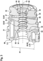
- Fig. 3 shows a perspective sectional view of the distributor 30.
- the section plane contains the axis of rotation 13.
- the distributor 30 is a one-piece part providing the second control surface 80 and the first to seventh fluid chamber 31 - 37.
- the planar second control surface 80 is perpendicular to the axis of rotation 13. It has fourteen second control openings 3.1 - 3.14 which are nearly equally distributed along a second circle 81 in numerical order.
- the center of the second circle 81 is defined by the axis of rotation 13, wherein its diameter is equal to the diameter of the first circle (no. 72 in Fig. 2 ).
- the second control openings 3.1 - 3.14 are nearly identical to each other, wherein they are formed like an oblong hole which extends in radial direction.
- the distributer 30 has an outer circumferential surface 39 which rotationally symmetric with respect to the axis of rotation 13 and which is adapted to the first casing part (no. 61 in Fig. 1 ) in a fluid tight manner.
- the outer circumferential surface 39 delimits the first, the sixth, the fourth, the seventh and the fifth annular fluid chamber 31; 36; 34; 37; 35 in sections each.
- each first control opening overlaps each second control opening 3.1 - 3.14 in at least in one rotational position of the rotor.
- the first, the sixth, the fourth, the seventh and the fifth annular fluid chamber 31; 36; 34; 37; 35 are for formed by annular grooves at the outer circumferential surface 39 of the distributor 30, which are arranged in a row along the axis rotation 13 in the named order.
- first to fourth fluid chamber 31 - 34 with the second control openings 3.1 - 3.14 will be explained with reference to Fig. 4 below.
- These permanent connections are formed by channels inside the distributor 30, which were made during the casting of the blank distributor.
- Each of these connections has a straight section 82 which is parallel to the axis rotation 13. At the leftmost side of the distributor these straight sections 82 are very close to each other such that no further channel can pass between two neighboring straight sections 82. Therefore, the first fluid chamber 31 which is closest to the second control surface 80 is fluidically connected to the second control valve which is located outside of the distributor.
- the sixth fluid chamber is located next to the first fluid chamber 31 at the outer circumferential surface 39 of the distributor 30. At this location the straight section 83 is no longer present.
- the corresponding space can be used for a channel 84 connecting the first control valve (at no. 90) and the sixth fluid chamber 36.
- the fifth fluid chamber 35 provides a fluid connection between the first and the second control valve, which is marked in Fig. 5 with no. 35.
- the bore 90 is cylindrical with respect to the axis of rotation 13.
- the bore 90 has a first, a second, a third, a fourth and a fifth annular groove 91; 92; 93; 94; 95 which are located in a row along the axis of rotation 13 in the named order.
- the first annular groove 91 is permanently connected to the sixth fluid chamber 36 which is permanently connected to the first working port. In Fig. 5 the location of the sixth fluid chamber is marked with no. 36.
- the second annular groove 92 delimits the second fluid chamber 32 in part. It has two purposes. Firstly it is part of an orifice, which is adjustable by a movement of the spool of the first control valve. Secondly as part of the second fluid chamber 32 it provides a connection 85 to at least one associated second control opening 3.1 - 3.14, wherein according to Fig. 4 three such connections are provided.
- the third annular groove 93 delimits the third fluid chamber 33 in part. It has two purposes. Firstly it as part of an orifice, which is adjustable by a movement of the spool of the first control valve. Secondly as part of the third fluid chamber 33 it provides a connection 86 to at least one associated second control opening 3.1 - 3.14, wherein according to Fig. 4 three such connections are provided.
- the fourth annular groove 94 is permanently connected to the seventh annular fluid chamber 37, which is permanently connected the second working port.
- the location of the seventh fluid chamber is marked with no. 37.
- the fifth annular groove 95 is permanently connected to the fifth fluid chamber 35, which provides a connection to the second control valve.
- Fig. 4 shows a schematic diagram comprising the pistons 1.1 - 1.18, the first and second control openings 2.1 - 2-18; 3.1 - 3.14 and the first to fourth fluid chamber 31; 32; 33; 34.
- some of the reference numerals 1.1 - 1.18; 2.1 - 2.18; 3.1 - 3.14 were missed out. In all three cases there is a consecutive numbering, which ascends from left to right in Fig. 4 .
- the pistons 1.1 - 1.18 are equally distributed around the axis of rotation (no. 13 in Fig. 2 ), wherein they are shown in an unfolded way in Fig. 4 .
- the cam surface 21, the rotor 70 and the distributor 30 are shown correspondingly.
- the the two dash-dot lines 15 refer to the same circumferential position with respect to the axis of rotation (no. 13 in Fig. 2 , namely the center of piston 1.18.
- the cam surface 21 on the inner circumference of the second casing part (no. 62 in Fig. 1 ) has seven lobes, wherein it is basically sinus shaped.
- the fluid pressures in the cylinders 73 urges the moveable pistons 1.1 - 1.18 against the cam surface 21 such that they follow the cam surface 21 when the rotor 70 rotates. In consequence during one rotation of the rotor 70 each piston 1.1 - 1.18 executes seven strokes.
- the distributor 30 has fourteen second control control openings 3.1 - 3.14, i.e., two for each lobe of the cam surface 21.
- the rotational position of the distributor 30 relative to the cam surface 21 is fixed by a notch 38 in the distributor 30 which engages with a cylindrical pin fixed in the first casing part (no. 61 in Fig. 1 ), such that each dead center (maximum or minimum) of the cam surface 21 is located between two neighboring second control openings 3.1 - 3.14.
- the rotor 70 has eighteen pistons 1.1 - 1.18 which are accommodated in a respective cylinder 73 of the rotor 70 so that they can move linearly.
- Each piston 1.1 - 1.18 contacts the cam surface 21 via a roller (no. 74 in Fig. 2 ) which is not shown in Fig. 4 .
- Each cylinder 73 has as a respective first control opening 2.1 - 2.18, wherein each first control opening 2.1 - 2.18 overlaps each second control opening 3.1 - 3.14 during one rotation of the rotor 70.
- first and second group of second control openings A; B wherein neighboring second control openings 3.1 - 3.14 belong to a different first or second group A; B.
- the first fluid chamber 31 is permanently connected to four second control openings 3.2; 3.4; 3.10. 3.12 belonging to the first group A.
- the second fluid chamber 32 is permanently connected to three second control openings 3.6; 3.8; 3.14 belonging to the first group A.
- the third fluid chamber 33 is permanently connected to three second control openings 3.1; 3.7; 3.9 belonging to the second group B.
- the fourth fluid chamber 34 is permanently connected to four second control openings 3.3; 3.5; 3.11; 3.13 belonging to second group B.
- Fig. 4 is a preferred embodiment wherein other configurations are possible.
- the configuration according to Fig. 4 gives a good compromise between a low number of pistons 1.1 - 1.18 and a low torque ripple.
- Fig. 5 shows a schematic comprising the first and the second control valve 41; 42, the first to seventh fluid chamber 31 - 37 and the first and the second working port 11; 12.
- the first and the second control valve 41; 42 and the first and the second auxiliary valve 45; 56 are preferably configured as spool valves respectively.
- the first control valve 41; has a first and a second position 51; 52, wherein the second control valve 42 has a third and a fourth position 53; 54.
- the first and third positions 51; 53 are active such that all second control openings belonging to group A are connected to the first port 11, wherein all second control openings belonging to group B are connected to the second working port 12.
- first control valve 41 connects the first working port 11 with the second fluid chamber 32 and the second working port 12 with the third fluid chamber 33.
- the second control valve 42 connects the first working port 11 with the first fluid chamber 31 and the second working port 12 with the fourth fluid chamber 34.
- the fifth fluid chamber 35 is not used in this switching position, in which the multi piston machine works with the maximum displacement volume.
- the second to maximum displacement volume is an active, when the first control valve 41 is in the second position 52, wherein the second control valve 42 is in the third position 53. Then the first working port 11 is only connected to the first fluid chamber 31, wherein the second working port 12 is only connected to the fourth fluid chamber 34 wherein both connections are provided by the second control valve 42.
- the first control valve 41 provides a direct connection between the second and the third fluid chamber 32; 33 via its first short circuit connection 55. Consequently, the second control openings 3.1; 3.6; 3.7; 3.8; 3.9; 3.14 are connected to each other. In this state eight of the fourteen second control openings contribute to the net displacement volume so that the net displacement volume is 8/14 of the maximum displacement volume.
- the third to maximum displacement volume is an active, when the first control valve 41 is in the first position 51, wherein the second control valve 42 is in the fourth position 54. Then the first working port 11 is only connected to the second fluid chamber 32, wherein the second working port 12 is only connected to the third fluid chamber 33 wherein both connections are provided by the first control valve 41.
- the second control valve 42 provides a direct connection between the first and the fourth fluid chamber 31; 34 via its second short circuit connection 56. Consequently, the second control openings 3.2; 3.3; 3.4;3.5; 3.10; 3.11; 3.12; 3.13 are connected to each other. In this state six of the fourteen second control openings contribute to the net displacement volume so that the net displacement volume is 6/14 of the maximum displacement volume.
- first control valve 41 When first control valve 41 is switch into its second position 52 and the second control valve 42 is switched into its fourth position 54 the multi piston machine is in a free-wheeling state. There is a direct connection between the first and the second working 11; 12 ports via the fifth fluid chamber 35. Furthermore, the first to fourth fluid chamber 31 - 34 are short circuited to each other. When the multi piston machine drives an associated wheel of a vehicle, the wheel can be turned with low resistance, wherein fluid pressure at the first or second working port 11; 12 does not drive the vehicle.
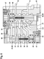
- Fig. 6 show a partial section of the multi piston machine showing the first and the second control valve 41; 42.
- the spool 48 of the first control valve 41 is accommodated in the central bore 90 of the distributor 30 in a linearly moveable manner. It is urged into the shown first position (no. 51 in Fig. 4 ) by a spring 47.
- the first control port is permanently connected to the chamber marked with no. 43. The corresponding pressure acts on the spool 48 and on the first auxiliary valve 45.
- the spool 49 of the second control valve 42 is accommodated in the first casing part 61 in a linearly movable manner, i.e., outside the distributor 30. It is urged into the shown third position (no. 53 in Fig. 4 ) by a spring 47.
- the second control port is permanently connected to the chamber marked with no. 44. The corresponding pressure acts on the spool 49 and on the second auxiliary valve 46.
- the spools 48 and 49 including the auxiliary valves 45; 46 are configured identical to each other.
Landscapes
- Engineering & Computer Science (AREA)
- Chemical & Material Sciences (AREA)
- Combustion & Propulsion (AREA)
- Mechanical Engineering (AREA)
- General Engineering & Computer Science (AREA)
- Hydraulic Motors (AREA)
Claims (10)
- Machine à pistons multiples (10) comportant un rotor (70), qui est situé à l'intérieur d'un carter (60) et qui est rotatif autour d'un axe de rotation (13), le carter (60) comportant un premier et un second orifice de travail (11 ; 12), un premier nombre de pistons (1.1 - 1.18) étant reçus dans le rotor (70) d'une manière linéairement mobile, les pistons (1.1 - 1.18) pouvant entrer en contact avec une surface de came (21) du carter (60), qui comprend un deuxième nombre de lobes (22), de sorte que le nombre de courses d'un seul piston (1.1 - 1.18) au cours d'un tour du rotor (70) soit égal au deuxième nombre, chaque piston (1.1 - 1.18) comportant une première ouverture de commande (2.1 - 2.18) associée au niveau d'une première surface de commande (71) du rotor (70), les premières ouvertures de commande (2.1 - 2.18) étant situées le long d'un premier cercle (72) dont le centre est défini par l'axe de rotation (13), le carter (60) comportant une seconde surface de commande (80) qui vient en butée contre la première surface de commande (71), la seconde surface de commande (80) comportant un troisième nombre de secondes ouvertures de commande (3.1 - 3.14), qui sont situées le long d'un second cercle (81), dont le centre est défini par l'axe de rotation (13), chaque première ouverture de commande (2.1 - 2.18) pouvant chevaucher chacune des secondes ouvertures (3.1 - 3.14) dans au moins une position de rotation du rotor (70) respectivement, une première, une deuxième, une troisième et une quatrième chambres de fluide (31 ; 32 ; 33 ; 34) étant présentes, chaque seconde ouverture de commande (3.1 - 3.14) étant reliée de façon permanente à une seule des première à quatrième chambres de fluide (31 ; 32 ; 33 ; 34),
caractérisée en ce que la machine à pistons multiples (10) peut être commutée entre au moins trois volumes de déplacement non nuls au moyen d'une première et d'une seconde soupape de commande (41 ; 42), la première et la seconde soupape de commande (41 ; 42) étant reliées respectivement au premier et au second orifice de travail (11 ; 12) respectivement, les première à quatrième chambres de fluide (31 - 34) étant annulaires par rapport à l'axe de rotation (13), étant réparties le long de l'axe de rotation (13), la première soupape de commande (41) étant disposée radialement à l'intérieur des première à quatrième chambres de fluide (31 - 34), la première soupape de commande (41) étant en communication fluidique avec la deuxième et la troisième chambre de fluide (32 ; 33), la seconde soupape de commande (42) étant disposée radialement à l'extérieur de la première à la quatrième chambre de fluide (31 - 34), la seconde soupape de commande (42) étant en communication fluidique avec la première et la quatrième chambre de fluide (31 ; 34), la première chambre (31) étant située plus près de la seconde surface de commande (80) que la deuxième à la quatrième chambre de fluide (32 - 34). - Machine à pistons multiples (10) selon la revendication 1,
le carter comprenant (60) un distributeur (30) et une première partie de carter (61), le distributeur (30) présentant une surface circonférentielle extérieure (39) qui est rotativement symétrique par rapport à l'axe de rotation (13), les secondes ouvertures de commande (3.1 - 3.14) étant situées au niveau du distributeur (30), la surface circonférentielle extérieure (39) délimitant la première et la quatrième chambre de fluide (31 ; 34) en sections, la deuxième et la troisième chambre de fluide (32 ; 33) étant situées entièrement à l'intérieur du distributeur (30). - Machine à pistons multiples (10) selon l'une quelconque des revendications précédentes,
un tiroir (48) de la première soupape de commande (41) étant reçu dans le distributeur (30) d'une manière mobile linéaire, la deuxième et la troisième chambre de fluide (32 ; 33) étant délimitées par ledit tiroir (48) et le distributeur (30), de sorte que la deuxième et la troisième chambre de fluide (32 ; 33) fassent chacune partie d'un orifice qui est réglable par le mouvement dudit tiroir (48). - Machine à pistons multiples (10) selon la revendication 2 ou 3,
la surface circonférentielle extérieure (39) délimitant une cinquième chambre de fluide (35) annulaire en sections, la première et la seconde soupape de commande (41 ; 42) étant en communication fluidique par l'intermédiaire de la cinquième chambre de fluide (35). - Machine à pistons multiples (10) selon la revendication 4,
la première, la quatrième et la cinquième chambre de fluide (31 ; 32 ; 35) étant disposées en rangée le long de l'axe de rotation (13) dans l'ordre indiqué. - Machine à pistons multiples (10) selon l'une quelconque des revendications 2 à 5,
la surface circonférentielle extérieure (39) délimitant une sixième chambre de fluide (36) annulaire en sections, la sixième chambre de fluide (36) étant en communication fluidique avec la première et la seconde soupape de commande (41 ; 42) et le premier orifice de travail. - Machine à pistons multiples (10) selon la revendication 6, se rapportant à la revendication 5,
la sixième chambre de fluide (36) étant située entre la première et la quatrième chambre de fluide (31 ; 34). - Machine à pistons multiples (10) selon l'une quelconque des revendications 2 à 7,
la surface circonférentielle extérieure (39) délimitant une septième chambre de fluide (37) annulaire en sections, la septième chambre de fluide (37) étant en communication fluidique avec la première et la seconde soupape de commande (41 ; 42) et le second orifice de travail (12). - Machine à pistons multiples (10) selon la revendication 8, se rapportant à la revendication 5,
la septième chambre de fluide (36) étant située entre la quatrième et la cinquième chambre de fluide (34 ; 35). - Machine à pistons multiples (10) selon l'une quelconque des revendications précédentes,
chaque communication fluidique entre une seconde ouverture de commande (3.1 - 3.14) et une première à quatrième chambre de fluide (31 - 34) correspondante comprenant une section droite (82) qui est parallèle à l'axe de rotation (13).
Priority Applications (1)
| Application Number | Priority Date | Filing Date | Title |
|---|---|---|---|
| EP22205722.6A EP4365436B1 (fr) | 2022-11-07 | 2022-11-07 | Machine à pistons multiples avec au moins trois volumes de déplacement commutables et une première soupape de commande centrale |
Applications Claiming Priority (1)
| Application Number | Priority Date | Filing Date | Title |
|---|---|---|---|
| EP22205722.6A EP4365436B1 (fr) | 2022-11-07 | 2022-11-07 | Machine à pistons multiples avec au moins trois volumes de déplacement commutables et une première soupape de commande centrale |
Publications (2)
| Publication Number | Publication Date |
|---|---|
| EP4365436A1 EP4365436A1 (fr) | 2024-05-08 |
| EP4365436B1 true EP4365436B1 (fr) | 2025-05-07 |
Family
ID=84329534
Family Applications (1)
| Application Number | Title | Priority Date | Filing Date |
|---|---|---|---|
| EP22205722.6A Active EP4365436B1 (fr) | 2022-11-07 | 2022-11-07 | Machine à pistons multiples avec au moins trois volumes de déplacement commutables et une première soupape de commande centrale |
Country Status (1)
| Country | Link |
|---|---|
| EP (1) | EP4365436B1 (fr) |
Family Cites Families (5)
| Publication number | Priority date | Publication date | Assignee | Title |
|---|---|---|---|---|
| DE3706460A1 (de) | 1986-10-31 | 1988-09-08 | Rexroth Mannesmann Gmbh | Kolbenmaschine mit umschaltbarem hubraum |
| FI104014B1 (fi) | 1994-05-18 | 1999-10-29 | Valmet Voimansiirto Oy | Radiaalimäntähydraulimoottori ja menetelmä radiaalihydraulimoottorin säätämiseksi |
| JP3127842B2 (ja) | 1996-11-01 | 2001-01-29 | ダイキン工業株式会社 | カムモータ装置 |
| FR2940671B1 (fr) * | 2008-12-31 | 2011-04-22 | Poclain Hydraulics Ind | Circuit de transmission hydraulique |
| EP4102051A1 (fr) * | 2021-06-07 | 2022-12-14 | Robert Bosch GmbH | Machine à pistons multiples comportant au moins trois volumes de déplacement commutables |
-
2022
- 2022-11-07 EP EP22205722.6A patent/EP4365436B1/fr active Active
Also Published As
| Publication number | Publication date |
|---|---|
| EP4365436A1 (fr) | 2024-05-08 |
Similar Documents
| Publication | Publication Date | Title |
|---|---|---|
| EP4102052A1 (fr) | Machine à pistons multiples comportant au moins trois volumes de déplacement commutables | |
| US7273004B2 (en) | Reciprocating machine | |
| US3961562A (en) | Multiple pump assembly | |
| US4807519A (en) | Piston machine with changeable displacement | |
| EP2250068B1 (fr) | Contrôleur de fluide doté de multiples débitmètres | |
| CN114635824B (zh) | 凸轮凸角结构的静液压径向柱塞单元 | |
| KR100506125B1 (ko) | 캠모터 장치 | |
| US5090295A (en) | Radial piston engine | |
| US4532854A (en) | Selectively operative multi-displacement pump or motor | |
| US4297086A (en) | Fluid motor-pump unit | |
| US20190153865A1 (en) | Cam Profile for a Hydrostatic Radial Piston Machine, and Hydrostatic Radial Piston Machine | |
| EP0288854B1 (fr) | Machine hydraulique rotative | |
| JP4468177B2 (ja) | 液圧ポンプまたは液圧モーター | |
| EP4365436B1 (fr) | Machine à pistons multiples avec au moins trois volumes de déplacement commutables et une première soupape de commande centrale | |
| US3587401A (en) | Hydraulic radial motor | |
| EP4345284B1 (fr) | Machine à pistons multiples avec relation constante entre le volume de fluide et l'angle de rotation dans chaque position de rotation | |
| EP3608535B1 (fr) | Machine à piston radial hydrostatique | |
| US10690109B2 (en) | Distribution device for a hydraulic machine and a hydraulic machine fitted with such a device | |
| US4494915A (en) | Hydrostatic steering unit with cylindrical slide member within clindrical valve sleeve | |
| GB2043001A (en) | Hydrostatic steering device | |
| US11598332B2 (en) | Hydraulic orbital machine and method for adjusting an orbital machine | |
| US8079298B2 (en) | Compact hydraulic mechanism with radial pistons | |
| EP3885571B1 (fr) | Moteur hydraulique à bobine intégrée en série/parallèle | |
| JP3675995B2 (ja) | カムモータ装置 | |
| EP2389513B1 (fr) | Ensemble de deplacement pour un dispositif hydraulique |
Legal Events
| Date | Code | Title | Description |
|---|---|---|---|
| PUAI | Public reference made under article 153(3) epc to a published international application that has entered the european phase |
Free format text: ORIGINAL CODE: 0009012 |
|
| STAA | Information on the status of an ep patent application or granted ep patent |
Free format text: STATUS: THE APPLICATION HAS BEEN PUBLISHED |
|
| AK | Designated contracting states |
Kind code of ref document: A1 Designated state(s): AL AT BE BG CH CY CZ DE DK EE ES FI FR GB GR HR HU IE IS IT LI LT LU LV MC ME MK MT NL NO PL PT RO RS SE SI SK SM TR |
|
| STAA | Information on the status of an ep patent application or granted ep patent |
Free format text: STATUS: REQUEST FOR EXAMINATION WAS MADE |
|
| 17P | Request for examination filed |
Effective date: 20241108 |
|
| RBV | Designated contracting states (corrected) |
Designated state(s): AL AT BE BG CH CY CZ DE DK EE ES FI FR GB GR HR HU IE IS IT LI LT LU LV MC ME MK MT NL NO PL PT RO RS SE SI SK SM TR |
|
| GRAP | Despatch of communication of intention to grant a patent |
Free format text: ORIGINAL CODE: EPIDOSNIGR1 |
|
| STAA | Information on the status of an ep patent application or granted ep patent |
Free format text: STATUS: GRANT OF PATENT IS INTENDED |
|
| RIC1 | Information provided on ipc code assigned before grant |
Ipc: F04B 1/0413 20200101ALN20250129BHEP Ipc: F04B 1/1071 20200101ALN20250129BHEP Ipc: F04B 1/063 20200101ALN20250129BHEP Ipc: F03C 1/30 20060101ALI20250129BHEP Ipc: F03C 1/247 20060101ALI20250129BHEP Ipc: F03C 1/24 20060101ALI20250129BHEP Ipc: F03C 1/40 20060101AFI20250129BHEP |
|
| GRAS | Grant fee paid |
Free format text: ORIGINAL CODE: EPIDOSNIGR3 |
|
| INTG | Intention to grant announced |
Effective date: 20250220 |
|
| GRAA | (expected) grant |
Free format text: ORIGINAL CODE: 0009210 |
|
| STAA | Information on the status of an ep patent application or granted ep patent |
Free format text: STATUS: THE PATENT HAS BEEN GRANTED |
|
| AK | Designated contracting states |
Kind code of ref document: B1 Designated state(s): AL AT BE BG CH CY CZ DE DK EE ES FI FR GB GR HR HU IE IS IT LI LT LU LV MC ME MK MT NL NO PL PT RO RS SE SI SK SM TR |
|
| REG | Reference to a national code |
Ref country code: GB Ref legal event code: FG4D |
|
| REG | Reference to a national code |
Ref country code: CH Ref legal event code: EP |
|
| REG | Reference to a national code |
Ref country code: DE Ref legal event code: R096 Ref document number: 602022014192 Country of ref document: DE |
|
| REG | Reference to a national code |
Ref country code: IE Ref legal event code: FG4D |
|
| REG | Reference to a national code |
Ref country code: NL Ref legal event code: MP Effective date: 20250507 |
|
| PG25 | Lapsed in a contracting state [announced via postgrant information from national office to epo] |
Ref country code: PT Free format text: LAPSE BECAUSE OF FAILURE TO SUBMIT A TRANSLATION OF THE DESCRIPTION OR TO PAY THE FEE WITHIN THE PRESCRIBED TIME-LIMIT Effective date: 20250908 Ref country code: ES Free format text: LAPSE BECAUSE OF FAILURE TO SUBMIT A TRANSLATION OF THE DESCRIPTION OR TO PAY THE FEE WITHIN THE PRESCRIBED TIME-LIMIT Effective date: 20250507 Ref country code: FI Free format text: LAPSE BECAUSE OF FAILURE TO SUBMIT A TRANSLATION OF THE DESCRIPTION OR TO PAY THE FEE WITHIN THE PRESCRIBED TIME-LIMIT Effective date: 20250507 |
|
| REG | Reference to a national code |
Ref country code: LT Ref legal event code: MG9D |
|
| PG25 | Lapsed in a contracting state [announced via postgrant information from national office to epo] |
Ref country code: NO Free format text: LAPSE BECAUSE OF FAILURE TO SUBMIT A TRANSLATION OF THE DESCRIPTION OR TO PAY THE FEE WITHIN THE PRESCRIBED TIME-LIMIT Effective date: 20250807 Ref country code: GR Free format text: LAPSE BECAUSE OF FAILURE TO SUBMIT A TRANSLATION OF THE DESCRIPTION OR TO PAY THE FEE WITHIN THE PRESCRIBED TIME-LIMIT Effective date: 20250808 |
|
| PG25 | Lapsed in a contracting state [announced via postgrant information from national office to epo] |
Ref country code: PL Free format text: LAPSE BECAUSE OF FAILURE TO SUBMIT A TRANSLATION OF THE DESCRIPTION OR TO PAY THE FEE WITHIN THE PRESCRIBED TIME-LIMIT Effective date: 20250507 Ref country code: NL Free format text: LAPSE BECAUSE OF FAILURE TO SUBMIT A TRANSLATION OF THE DESCRIPTION OR TO PAY THE FEE WITHIN THE PRESCRIBED TIME-LIMIT Effective date: 20250507 |
|
| REG | Reference to a national code |
Ref country code: AT Ref legal event code: MK05 Ref document number: 1792709 Country of ref document: AT Kind code of ref document: T Effective date: 20250507 |
|
| PG25 | Lapsed in a contracting state [announced via postgrant information from national office to epo] |
Ref country code: BG Free format text: LAPSE BECAUSE OF FAILURE TO SUBMIT A TRANSLATION OF THE DESCRIPTION OR TO PAY THE FEE WITHIN THE PRESCRIBED TIME-LIMIT Effective date: 20250507 |
|
| PG25 | Lapsed in a contracting state [announced via postgrant information from national office to epo] |
Ref country code: HR Free format text: LAPSE BECAUSE OF FAILURE TO SUBMIT A TRANSLATION OF THE DESCRIPTION OR TO PAY THE FEE WITHIN THE PRESCRIBED TIME-LIMIT Effective date: 20250507 |
|
| PG25 | Lapsed in a contracting state [announced via postgrant information from national office to epo] |
Ref country code: AT Free format text: LAPSE BECAUSE OF FAILURE TO SUBMIT A TRANSLATION OF THE DESCRIPTION OR TO PAY THE FEE WITHIN THE PRESCRIBED TIME-LIMIT Effective date: 20250507 |
|
| PG25 | Lapsed in a contracting state [announced via postgrant information from national office to epo] |
Ref country code: RS Free format text: LAPSE BECAUSE OF FAILURE TO SUBMIT A TRANSLATION OF THE DESCRIPTION OR TO PAY THE FEE WITHIN THE PRESCRIBED TIME-LIMIT Effective date: 20250807 |
|
| PG25 | Lapsed in a contracting state [announced via postgrant information from national office to epo] |
Ref country code: IS Free format text: LAPSE BECAUSE OF FAILURE TO SUBMIT A TRANSLATION OF THE DESCRIPTION OR TO PAY THE FEE WITHIN THE PRESCRIBED TIME-LIMIT Effective date: 20250907 |
|
| PG25 | Lapsed in a contracting state [announced via postgrant information from national office to epo] |
Ref country code: LV Free format text: LAPSE BECAUSE OF FAILURE TO SUBMIT A TRANSLATION OF THE DESCRIPTION OR TO PAY THE FEE WITHIN THE PRESCRIBED TIME-LIMIT Effective date: 20250507 |
|
| PG25 | Lapsed in a contracting state [announced via postgrant information from national office to epo] |
Ref country code: DK Free format text: LAPSE BECAUSE OF FAILURE TO SUBMIT A TRANSLATION OF THE DESCRIPTION OR TO PAY THE FEE WITHIN THE PRESCRIBED TIME-LIMIT Effective date: 20250507 Ref country code: SM Free format text: LAPSE BECAUSE OF FAILURE TO SUBMIT A TRANSLATION OF THE DESCRIPTION OR TO PAY THE FEE WITHIN THE PRESCRIBED TIME-LIMIT Effective date: 20250507 |
|
| PGFP | Annual fee paid to national office [announced via postgrant information from national office to epo] |
Ref country code: FR Payment date: 20251125 Year of fee payment: 4 |
|
| PG25 | Lapsed in a contracting state [announced via postgrant information from national office to epo] |
Ref country code: CZ Free format text: LAPSE BECAUSE OF FAILURE TO SUBMIT A TRANSLATION OF THE DESCRIPTION OR TO PAY THE FEE WITHIN THE PRESCRIBED TIME-LIMIT Effective date: 20250507 |
|
| PG25 | Lapsed in a contracting state [announced via postgrant information from national office to epo] |
Ref country code: EE Free format text: LAPSE BECAUSE OF FAILURE TO SUBMIT A TRANSLATION OF THE DESCRIPTION OR TO PAY THE FEE WITHIN THE PRESCRIBED TIME-LIMIT Effective date: 20250507 |
|
| PG25 | Lapsed in a contracting state [announced via postgrant information from national office to epo] |
Ref country code: SK Free format text: LAPSE BECAUSE OF FAILURE TO SUBMIT A TRANSLATION OF THE DESCRIPTION OR TO PAY THE FEE WITHIN THE PRESCRIBED TIME-LIMIT Effective date: 20250507 |
|
| PG25 | Lapsed in a contracting state [announced via postgrant information from national office to epo] |
Ref country code: IT Free format text: LAPSE BECAUSE OF FAILURE TO SUBMIT A TRANSLATION OF THE DESCRIPTION OR TO PAY THE FEE WITHIN THE PRESCRIBED TIME-LIMIT Effective date: 20250507 |
|
| REG | Reference to a national code |
Ref country code: DE Ref legal event code: R097 Ref document number: 602022014192 Country of ref document: DE |
|
| PG25 | Lapsed in a contracting state [announced via postgrant information from national office to epo] |
Ref country code: RO Free format text: LAPSE BECAUSE OF FAILURE TO SUBMIT A TRANSLATION OF THE DESCRIPTION OR TO PAY THE FEE WITHIN THE PRESCRIBED TIME-LIMIT Effective date: 20250507 |
|
| PLBE | No opposition filed within time limit |
Free format text: ORIGINAL CODE: 0009261 |
|
| STAA | Information on the status of an ep patent application or granted ep patent |
Free format text: STATUS: NO OPPOSITION FILED WITHIN TIME LIMIT |
|
| REG | Reference to a national code |
Ref country code: CH Ref legal event code: L10 Free format text: ST27 STATUS EVENT CODE: U-0-0-L10-L00 (AS PROVIDED BY THE NATIONAL OFFICE) Effective date: 20260318 |
|
| PGFP | Annual fee paid to national office [announced via postgrant information from national office to epo] |
Ref country code: DE Payment date: 20260126 Year of fee payment: 4 |
|
| 26N | No opposition filed |
Effective date: 20260210 |