EP4370820B1 - Verstärkter druckbehälter - Google Patents
Verstärkter druckbehälter Download PDFInfo
- Publication number
- EP4370820B1 EP4370820B1 EP22741775.5A EP22741775A EP4370820B1 EP 4370820 B1 EP4370820 B1 EP 4370820B1 EP 22741775 A EP22741775 A EP 22741775A EP 4370820 B1 EP4370820 B1 EP 4370820B1
- Authority
- EP
- European Patent Office
- Prior art keywords
- dome
- longitudinal end
- pressure vessel
- liner
- shaped longitudinal
- Prior art date
- Legal status (The legal status is an assumption and is not a legal conclusion. Google has not performed a legal analysis and makes no representation as to the accuracy of the status listed.)
- Active
Links
Images


Classifications
-
- F—MECHANICAL ENGINEERING; LIGHTING; HEATING; WEAPONS; BLASTING
- F17—STORING OR DISTRIBUTING GASES OR LIQUIDS
- F17C—VESSELS FOR CONTAINING OR STORING COMPRESSED, LIQUEFIED OR SOLIDIFIED GASES; FIXED-CAPACITY GAS-HOLDERS; FILLING VESSELS WITH, OR DISCHARGING FROM VESSELS, COMPRESSED, LIQUEFIED, OR SOLIDIFIED GASES
- F17C1/00—Pressure vessels, e.g. gas cylinder, gas tank, replaceable cartridge
- F17C1/16—Pressure vessels, e.g. gas cylinder, gas tank, replaceable cartridge constructed of plastics materials
-
- F—MECHANICAL ENGINEERING; LIGHTING; HEATING; WEAPONS; BLASTING
- F17—STORING OR DISTRIBUTING GASES OR LIQUIDS
- F17C—VESSELS FOR CONTAINING OR STORING COMPRESSED, LIQUEFIED OR SOLIDIFIED GASES; FIXED-CAPACITY GAS-HOLDERS; FILLING VESSELS WITH, OR DISCHARGING FROM VESSELS, COMPRESSED, LIQUEFIED, OR SOLIDIFIED GASES
- F17C13/00—Details of vessels or of the filling or discharging of vessels
- F17C13/002—Details of vessels or of the filling or discharging of vessels for vessels under pressure
-
- F—MECHANICAL ENGINEERING; LIGHTING; HEATING; WEAPONS; BLASTING
- F17—STORING OR DISTRIBUTING GASES OR LIQUIDS
- F17C—VESSELS FOR CONTAINING OR STORING COMPRESSED, LIQUEFIED OR SOLIDIFIED GASES; FIXED-CAPACITY GAS-HOLDERS; FILLING VESSELS WITH, OR DISCHARGING FROM VESSELS, COMPRESSED, LIQUEFIED, OR SOLIDIFIED GASES
- F17C2201/00—Vessel construction, in particular geometry, arrangement or size
- F17C2201/01—Shape
- F17C2201/0104—Shape cylindrical
- F17C2201/0109—Shape cylindrical with exteriorly curved end-piece
-
- F—MECHANICAL ENGINEERING; LIGHTING; HEATING; WEAPONS; BLASTING
- F17—STORING OR DISTRIBUTING GASES OR LIQUIDS
- F17C—VESSELS FOR CONTAINING OR STORING COMPRESSED, LIQUEFIED OR SOLIDIFIED GASES; FIXED-CAPACITY GAS-HOLDERS; FILLING VESSELS WITH, OR DISCHARGING FROM VESSELS, COMPRESSED, LIQUEFIED, OR SOLIDIFIED GASES
- F17C2201/00—Vessel construction, in particular geometry, arrangement or size
- F17C2201/01—Shape
- F17C2201/0104—Shape cylindrical
- F17C2201/0123—Shape cylindrical with variable thickness or diameter
-
- F—MECHANICAL ENGINEERING; LIGHTING; HEATING; WEAPONS; BLASTING
- F17—STORING OR DISTRIBUTING GASES OR LIQUIDS
- F17C—VESSELS FOR CONTAINING OR STORING COMPRESSED, LIQUEFIED OR SOLIDIFIED GASES; FIXED-CAPACITY GAS-HOLDERS; FILLING VESSELS WITH, OR DISCHARGING FROM VESSELS, COMPRESSED, LIQUEFIED, OR SOLIDIFIED GASES
- F17C2201/00—Vessel construction, in particular geometry, arrangement or size
- F17C2201/05—Size
- F17C2201/056—Small (<1 m3)
-
- F—MECHANICAL ENGINEERING; LIGHTING; HEATING; WEAPONS; BLASTING
- F17—STORING OR DISTRIBUTING GASES OR LIQUIDS
- F17C—VESSELS FOR CONTAINING OR STORING COMPRESSED, LIQUEFIED OR SOLIDIFIED GASES; FIXED-CAPACITY GAS-HOLDERS; FILLING VESSELS WITH, OR DISCHARGING FROM VESSELS, COMPRESSED, LIQUEFIED, OR SOLIDIFIED GASES
- F17C2201/00—Vessel construction, in particular geometry, arrangement or size
- F17C2201/05—Size
- F17C2201/058—Size portable (<30 l)
-
- F—MECHANICAL ENGINEERING; LIGHTING; HEATING; WEAPONS; BLASTING
- F17—STORING OR DISTRIBUTING GASES OR LIQUIDS
- F17C—VESSELS FOR CONTAINING OR STORING COMPRESSED, LIQUEFIED OR SOLIDIFIED GASES; FIXED-CAPACITY GAS-HOLDERS; FILLING VESSELS WITH, OR DISCHARGING FROM VESSELS, COMPRESSED, LIQUEFIED, OR SOLIDIFIED GASES
- F17C2203/00—Vessel construction, in particular walls or details thereof
- F17C2203/06—Materials for walls or layers thereof; Properties or structures of walls or their materials
- F17C2203/0602—Wall structures; Special features thereof
- F17C2203/0604—Liners
-
- F—MECHANICAL ENGINEERING; LIGHTING; HEATING; WEAPONS; BLASTING
- F17—STORING OR DISTRIBUTING GASES OR LIQUIDS
- F17C—VESSELS FOR CONTAINING OR STORING COMPRESSED, LIQUEFIED OR SOLIDIFIED GASES; FIXED-CAPACITY GAS-HOLDERS; FILLING VESSELS WITH, OR DISCHARGING FROM VESSELS, COMPRESSED, LIQUEFIED, OR SOLIDIFIED GASES
- F17C2203/00—Vessel construction, in particular walls or details thereof
- F17C2203/06—Materials for walls or layers thereof; Properties or structures of walls or their materials
- F17C2203/0602—Wall structures; Special features thereof
- F17C2203/0612—Wall structures
- F17C2203/0614—Single wall
- F17C2203/0621—Single wall with three layers
-
- F—MECHANICAL ENGINEERING; LIGHTING; HEATING; WEAPONS; BLASTING
- F17—STORING OR DISTRIBUTING GASES OR LIQUIDS
- F17C—VESSELS FOR CONTAINING OR STORING COMPRESSED, LIQUEFIED OR SOLIDIFIED GASES; FIXED-CAPACITY GAS-HOLDERS; FILLING VESSELS WITH, OR DISCHARGING FROM VESSELS, COMPRESSED, LIQUEFIED, OR SOLIDIFIED GASES
- F17C2203/00—Vessel construction, in particular walls or details thereof
- F17C2203/06—Materials for walls or layers thereof; Properties or structures of walls or their materials
- F17C2203/0634—Materials for walls or layers thereof
- F17C2203/0636—Metals
- F17C2203/0639—Steels
- F17C2203/0643—Stainless steels
-
- F—MECHANICAL ENGINEERING; LIGHTING; HEATING; WEAPONS; BLASTING
- F17—STORING OR DISTRIBUTING GASES OR LIQUIDS
- F17C—VESSELS FOR CONTAINING OR STORING COMPRESSED, LIQUEFIED OR SOLIDIFIED GASES; FIXED-CAPACITY GAS-HOLDERS; FILLING VESSELS WITH, OR DISCHARGING FROM VESSELS, COMPRESSED, LIQUEFIED, OR SOLIDIFIED GASES
- F17C2203/00—Vessel construction, in particular walls or details thereof
- F17C2203/06—Materials for walls or layers thereof; Properties or structures of walls or their materials
- F17C2203/0634—Materials for walls or layers thereof
- F17C2203/0636—Metals
- F17C2203/0646—Aluminium
-
- F—MECHANICAL ENGINEERING; LIGHTING; HEATING; WEAPONS; BLASTING
- F17—STORING OR DISTRIBUTING GASES OR LIQUIDS
- F17C—VESSELS FOR CONTAINING OR STORING COMPRESSED, LIQUEFIED OR SOLIDIFIED GASES; FIXED-CAPACITY GAS-HOLDERS; FILLING VESSELS WITH, OR DISCHARGING FROM VESSELS, COMPRESSED, LIQUEFIED, OR SOLIDIFIED GASES
- F17C2203/00—Vessel construction, in particular walls or details thereof
- F17C2203/06—Materials for walls or layers thereof; Properties or structures of walls or their materials
- F17C2203/0634—Materials for walls or layers thereof
- F17C2203/0658—Synthetics
- F17C2203/066—Plastics
-
- F—MECHANICAL ENGINEERING; LIGHTING; HEATING; WEAPONS; BLASTING
- F17—STORING OR DISTRIBUTING GASES OR LIQUIDS
- F17C—VESSELS FOR CONTAINING OR STORING COMPRESSED, LIQUEFIED OR SOLIDIFIED GASES; FIXED-CAPACITY GAS-HOLDERS; FILLING VESSELS WITH, OR DISCHARGING FROM VESSELS, COMPRESSED, LIQUEFIED, OR SOLIDIFIED GASES
- F17C2203/00—Vessel construction, in particular walls or details thereof
- F17C2203/06—Materials for walls or layers thereof; Properties or structures of walls or their materials
- F17C2203/0634—Materials for walls or layers thereof
- F17C2203/0658—Synthetics
- F17C2203/0663—Synthetics in form of fibers or filaments
- F17C2203/0665—Synthetics in form of fibers or filaments radially wound
-
- F—MECHANICAL ENGINEERING; LIGHTING; HEATING; WEAPONS; BLASTING
- F17—STORING OR DISTRIBUTING GASES OR LIQUIDS
- F17C—VESSELS FOR CONTAINING OR STORING COMPRESSED, LIQUEFIED OR SOLIDIFIED GASES; FIXED-CAPACITY GAS-HOLDERS; FILLING VESSELS WITH, OR DISCHARGING FROM VESSELS, COMPRESSED, LIQUEFIED, OR SOLIDIFIED GASES
- F17C2203/00—Vessel construction, in particular walls or details thereof
- F17C2203/06—Materials for walls or layers thereof; Properties or structures of walls or their materials
- F17C2203/0634—Materials for walls or layers thereof
- F17C2203/0658—Synthetics
- F17C2203/0663—Synthetics in form of fibers or filaments
- F17C2203/0673—Polymers
-
- F—MECHANICAL ENGINEERING; LIGHTING; HEATING; WEAPONS; BLASTING
- F17—STORING OR DISTRIBUTING GASES OR LIQUIDS
- F17C—VESSELS FOR CONTAINING OR STORING COMPRESSED, LIQUEFIED OR SOLIDIFIED GASES; FIXED-CAPACITY GAS-HOLDERS; FILLING VESSELS WITH, OR DISCHARGING FROM VESSELS, COMPRESSED, LIQUEFIED, OR SOLIDIFIED GASES
- F17C2205/00—Vessel construction, in particular mounting arrangements, attachments or identifications means
- F17C2205/03—Fluid connections, filters, valves, closure means or other attachments
- F17C2205/0302—Fittings, valves, filters, or components in connection with the gas storage device
- F17C2205/0305—Bosses, e.g. boss collars
-
- F—MECHANICAL ENGINEERING; LIGHTING; HEATING; WEAPONS; BLASTING
- F17—STORING OR DISTRIBUTING GASES OR LIQUIDS
- F17C—VESSELS FOR CONTAINING OR STORING COMPRESSED, LIQUEFIED OR SOLIDIFIED GASES; FIXED-CAPACITY GAS-HOLDERS; FILLING VESSELS WITH, OR DISCHARGING FROM VESSELS, COMPRESSED, LIQUEFIED, OR SOLIDIFIED GASES
- F17C2209/00—Vessel construction, in particular methods of manufacturing
- F17C2209/21—Shaping processes
- F17C2209/2154—Winding
-
- F—MECHANICAL ENGINEERING; LIGHTING; HEATING; WEAPONS; BLASTING
- F17—STORING OR DISTRIBUTING GASES OR LIQUIDS
- F17C—VESSELS FOR CONTAINING OR STORING COMPRESSED, LIQUEFIED OR SOLIDIFIED GASES; FIXED-CAPACITY GAS-HOLDERS; FILLING VESSELS WITH, OR DISCHARGING FROM VESSELS, COMPRESSED, LIQUEFIED, OR SOLIDIFIED GASES
- F17C2221/00—Handled fluid, in particular type of fluid
- F17C2221/01—Pure fluids
- F17C2221/012—Hydrogen
-
- F—MECHANICAL ENGINEERING; LIGHTING; HEATING; WEAPONS; BLASTING
- F17—STORING OR DISTRIBUTING GASES OR LIQUIDS
- F17C—VESSELS FOR CONTAINING OR STORING COMPRESSED, LIQUEFIED OR SOLIDIFIED GASES; FIXED-CAPACITY GAS-HOLDERS; FILLING VESSELS WITH, OR DISCHARGING FROM VESSELS, COMPRESSED, LIQUEFIED, OR SOLIDIFIED GASES
- F17C2223/00—Handled fluid before transfer, i.e. state of fluid when stored in the vessel or before transfer from the vessel
- F17C2223/01—Handled fluid before transfer, i.e. state of fluid when stored in the vessel or before transfer from the vessel characterised by the phase
- F17C2223/0107—Single phase
- F17C2223/0123—Single phase gaseous, e.g. CNG, GNC
-
- F—MECHANICAL ENGINEERING; LIGHTING; HEATING; WEAPONS; BLASTING
- F17—STORING OR DISTRIBUTING GASES OR LIQUIDS
- F17C—VESSELS FOR CONTAINING OR STORING COMPRESSED, LIQUEFIED OR SOLIDIFIED GASES; FIXED-CAPACITY GAS-HOLDERS; FILLING VESSELS WITH, OR DISCHARGING FROM VESSELS, COMPRESSED, LIQUEFIED, OR SOLIDIFIED GASES
- F17C2260/00—Purposes of gas storage and gas handling
- F17C2260/01—Improving mechanical properties or manufacturing
- F17C2260/011—Improving strength
-
- F—MECHANICAL ENGINEERING; LIGHTING; HEATING; WEAPONS; BLASTING
- F17—STORING OR DISTRIBUTING GASES OR LIQUIDS
- F17C—VESSELS FOR CONTAINING OR STORING COMPRESSED, LIQUEFIED OR SOLIDIFIED GASES; FIXED-CAPACITY GAS-HOLDERS; FILLING VESSELS WITH, OR DISCHARGING FROM VESSELS, COMPRESSED, LIQUEFIED, OR SOLIDIFIED GASES
- F17C2260/00—Purposes of gas storage and gas handling
- F17C2260/01—Improving mechanical properties or manufacturing
- F17C2260/012—Reducing weight
-
- F—MECHANICAL ENGINEERING; LIGHTING; HEATING; WEAPONS; BLASTING
- F17—STORING OR DISTRIBUTING GASES OR LIQUIDS
- F17C—VESSELS FOR CONTAINING OR STORING COMPRESSED, LIQUEFIED OR SOLIDIFIED GASES; FIXED-CAPACITY GAS-HOLDERS; FILLING VESSELS WITH, OR DISCHARGING FROM VESSELS, COMPRESSED, LIQUEFIED, OR SOLIDIFIED GASES
- F17C2260/00—Purposes of gas storage and gas handling
- F17C2260/01—Improving mechanical properties or manufacturing
- F17C2260/013—Reducing manufacturing time or effort
-
- F—MECHANICAL ENGINEERING; LIGHTING; HEATING; WEAPONS; BLASTING
- F17—STORING OR DISTRIBUTING GASES OR LIQUIDS
- F17C—VESSELS FOR CONTAINING OR STORING COMPRESSED, LIQUEFIED OR SOLIDIFIED GASES; FIXED-CAPACITY GAS-HOLDERS; FILLING VESSELS WITH, OR DISCHARGING FROM VESSELS, COMPRESSED, LIQUEFIED, OR SOLIDIFIED GASES
- F17C2260/00—Purposes of gas storage and gas handling
- F17C2260/04—Reducing risks and environmental impact
- F17C2260/042—Reducing risk of explosion
-
- F—MECHANICAL ENGINEERING; LIGHTING; HEATING; WEAPONS; BLASTING
- F17—STORING OR DISTRIBUTING GASES OR LIQUIDS
- F17C—VESSELS FOR CONTAINING OR STORING COMPRESSED, LIQUEFIED OR SOLIDIFIED GASES; FIXED-CAPACITY GAS-HOLDERS; FILLING VESSELS WITH, OR DISCHARGING FROM VESSELS, COMPRESSED, LIQUEFIED, OR SOLIDIFIED GASES
- F17C2270/00—Applications
- F17C2270/01—Applications for fluid transport or storage
- F17C2270/0165—Applications for fluid transport or storage on the road
- F17C2270/0168—Applications for fluid transport or storage on the road by vehicles
- F17C2270/0178—Cars
-
- F—MECHANICAL ENGINEERING; LIGHTING; HEATING; WEAPONS; BLASTING
- F17—STORING OR DISTRIBUTING GASES OR LIQUIDS
- F17C—VESSELS FOR CONTAINING OR STORING COMPRESSED, LIQUEFIED OR SOLIDIFIED GASES; FIXED-CAPACITY GAS-HOLDERS; FILLING VESSELS WITH, OR DISCHARGING FROM VESSELS, COMPRESSED, LIQUEFIED, OR SOLIDIFIED GASES
- F17C2270/00—Applications
- F17C2270/01—Applications for fluid transport or storage
- F17C2270/0165—Applications for fluid transport or storage on the road
- F17C2270/0184—Fuel cells
-
- Y—GENERAL TAGGING OF NEW TECHNOLOGICAL DEVELOPMENTS; GENERAL TAGGING OF CROSS-SECTIONAL TECHNOLOGIES SPANNING OVER SEVERAL SECTIONS OF THE IPC; TECHNICAL SUBJECTS COVERED BY FORMER USPC CROSS-REFERENCE ART COLLECTIONS [XRACs] AND DIGESTS
- Y02—TECHNOLOGIES OR APPLICATIONS FOR MITIGATION OR ADAPTATION AGAINST CLIMATE CHANGE
- Y02E—REDUCTION OF GREENHOUSE GAS [GHG] EMISSIONS, RELATED TO ENERGY GENERATION, TRANSMISSION OR DISTRIBUTION
- Y02E60/00—Enabling technologies; Technologies with a potential or indirect contribution to GHG emissions mitigation
- Y02E60/30—Hydrogen technology
- Y02E60/32—Hydrogen storage
Definitions
- the invention relates to pressure vessels for vehicles. More precisely, the invention relates to a pressure vessel and a vehicle comprising such a pressure vessel.
- High pressure vessels for vehicles generally comprise a hollow container, also called a liner, having a general cylindrical shape with two dome-shaped longitudinal ends and made of plastic material, such material being chosen for being lightweight and cheap to produce, or other material such as metal (e.g. aluminum).
- This container is intended for storing gas under pressure, for example dihydrogen, to be used by the vehicle equipped with the pressure vessel for diverse functions, such as source of power.
- gas under pressure exerts strong constraints on the inner surface of the container which may damage the integrity of the container and cause hazardous leakage, especially with combustible gas like dihydrogen.
- dome reinforcement part or dome reinforcement shell comprising a winding of filament, independently of the container and then, in a subsequent step, fitting the dome reinforcement shell on the container.
- the document DE 10 2017 208 492 A1 provides an example of such a dome reinforcement shell.
- the dome-shaped longitudinal ends of the container and the dome reinforcement shell are provided with a geodesic dome contour in order to cause a constant tension in the wounded reinforcing fibre in all point of the run of the fibre.
- dome reinforcement shell locally increases the stress concentration inside the wounded reinforcing fibre, in particular in the tip region of the dome reinforcement shell, which makes it necessary to use more reinforcing fibre than when there is no dome reinforcement shell used. Using more reinforcing fibre is not desirable because it is expansive, time consuming during the manufacture of the pressure vessel and the resulting vessel is heavier.
- a pressure vessel comprising:
- the mechanical properties of the pressure vessel are improved by reinforcing the first dome-shaped longitudinal end and the first intermediate portion.
- the stress is reduced inside the outer composite structure and inside the first dome reinforcement shell. This makes it possible to use less of fibre either for the manufacture of the first dome reinforcement shell and for the outer composite structure while maintaining good mechanical properties. This allows a weight reduction of the resulting pressure vessel. Further, this allows a reduction of manufacturing time as the time of winding the outer composite structure over the liner and the first dome reinforcement shell is reduced.
- first outer diameter D1 and the second outer diameter D2 an insertion area is created in the first intermediate portion such that the first dome reinforcement shell either flushes with the liner or does not protrude excessively which avoids application of an excessive stress inside the outer composite structure at the point where the first dome reinforcement shell would protrude.
- first outer diameter D1 and the second outer diameter D2 are such that the first dome reinforcement shell flushes with the liner.
- the outer surface of the pressure vessel is particularly smooth. This improves the application of the outer composite structure and reduces the stress level within the pressure vessel.
- the first dome reinforcement shell flushes with the liner is meant that the outer surface of the liner is geometrically blended with the outer surface of the first dome reinforcement shell.
- filament is meant continuous fiber tows, preferably carbon fibers, glass fibers or aramid fibers, impregnated with a liquid matrix so as to form a composite material, or not pre-impregnated (i.e. dry fibers).
- a liquid matrix so as to form a composite material, or not pre-impregnated (i.e. dry fibers).
- thermoset composites and the thermoplastic composites which are formed with a thermoset resin or a thermoplastic polymer as matrix.
- thermoset resin is formed by mixing two or more reactive components forming a reactive thermoset precursor, which reacts upon exposure to curing conditions (e.g. heat, UV or other radiations, or simply by contacting them with one another, etc.) to form the thermoset resin.
- the thermoset matrix must be fully cured to yield high performance composites. Once cured, the thermoset resin is solid and cannot be further processed or reshaped as the resin is unable to flow anymore.
- thermoset resins include unsaturated polyester, epoxy, vinyl ester, polyurea, isocyanurate, and polyurethane resins. It is possible to produce thermoset prepregs made of fibers impregnated with a reactive resin which has been only partially cured to make it tacky, but still soft. The prepregs can be stored and later further processed under pressure by heating or exposing the resin to UV to complete curing and consolidating the prepregs.
- thermoplastic polymer can change from a solid state (or non-flowable state) to a liquid state (or flowable state) and reverse by increasing and lowering the temperature, respectively.
- lowering the temperature of the thermoplastic drives the formation of crystals and the solidification of the thermoplastic.
- heating a semi-crystalline polymer above the melting temperature thereof melts the crystals and the thermoplastic can flow.
- thermoplastics examples include polyether ketones such as polyether ether ketone (PEEK), polyether ketone ketone (PEKK), poly ether ketone ketone ether ketone (PEKKEK), polyamides, such as polyamide 6 (PA6), polyamide 66 (PA66), polyamide 10 (PA10), polyamide 11 (PA11), polyamide 12 (PA12), polyolefins such as polyethylene (PE), polypropylene (PP), and the like.
- Amorphous thermoplastics do not form crystals and do not have a melting temperature. The amorphous thermoplastics solidify or become flowable depending on whether the material temperature is below or above the glass transition temperature thereof.
- thermoplastic polyurethane examples include polyetherimide (PEI), polysulfone (PSU), polyethersulfone (PES), polycarbonate (PC), polystyrene (PS), thermoplastic polyurethane (TPU), and the like.
- PEI polyetherimide
- PSU polysulfone
- PES polyethersulfone
- PC polycarbonate
- PS polystyrene
- TPU thermoplastic polyurethane
- the liner may be made in any material conventionally used for a pressure vessel, in particular for a pressure vessel for a vehicle.
- the liner may be made of metal, such as aluminum or steel, or may be made of plastic.
- the first dome reinforcement shell is, for example, a dome reinforcement shell as described in the prior art document previously discussed.
- a geodesic dome is meant to designate a dome structure based on a network of great circles at the surface of a hemisphere.
- the geodesic intersects to form triangular elements that have local triangular rigidity and also distribute the stress across the structure.
- a geodesic dome contour can be generated by the technique described in pages 244-245 of the "Handbook of Composite Reinforcements" by Stuart M. Lee (ISBN: 0-471-18861-1 ).
- the geodesic dome contour provides isotensoid loading of a filament.
- isotensoid refers to the property of the fully wound pressure vessel in which each filament of the outer composite structure which is wrapped around the liner and the first dome reinforcement shell experiences a constant pressure at all points in its path. In this configuration, virtually the entire stress imposed on the vessel by a compressed internal fluid is assumed by the filaments of the outer composite structure with very little of the stress being assumed by the liner.
- the first dome reinforcement shell has a shape complementary to the shape of the first dome-shaped longitudinal end of the liner, the first dome reinforcement shell also has a dome contour which is less concave toward the internal fluid storage chamber than a dome reinforcement shell having a geodesic dome contour.
- the shape of the first intermediate portion of the liner has an outer peripheral surface selected from the group consisting of cylindrical, frustoconical, curved and combinations thereof.
- the outer surface of the liner comprising the first dome reinforcement shell is particularly smooth. This improves the application of the outer composite structure and reduces the stress levels within the pressure vessel.
- the outer peripheral surface of the first intermediate portion is a combination of a first frustoconical surface and a first cylindrical surface.
- the liner can be seen as a stepped liner comprising a first tapered outer shoulder between the generally cylindrical central portion and the first dome-shaped longitudinal end.
- an angle ⁇ formed between the first frustoconical surface and the first cylindrical surface of the first intermediate portion is less than 15°, and preferably is less than 10°.
- This angle allows a smooth transition from the first frustoconical surface to the first cylindrical surface of the first intermediate portion and avoids the creation of sharp edges which may cause damages to the outer composite structure. This angle further allows reducing the stress inside the liner in the tip region of the first dome reinforcement shell.
- an angle ⁇ formed between the first frustoconical surface and an outer peripheral surface of the generally cylindrical central portion is less than 15°, and preferably is less than 10°.
- This angle allows a smooth transition from the first frustoconical surface to the outer peripheral surface of the generally cylindrical central portion and avoids the creation of sharp edges which may cause damages to the outer composite structure. Further, when the first intermediate portion includes a first tapered outer shoulder for accommodating the tip of the first dome reinforcement shell, this angle reduces the stress inside the liner in the tip region of the first dome reinforcement shell.
- a greatest distance between the dome contour of the first dome-shaped longitudinal end and the dome contour of a dome-shaped longitudinal end having a geodesic dome contour is comprised between 0.1% and 5% of the first outer diameter D1, preferably between 0.5% and 2.5% of the first outer diameter D1.
- the pressure vessel further comprises a hoop layer wound around the generally cylindrical central portion of the liner such that the first outer diameter D1 includes the hoop layer.
- a classical liner is a liner without step.
- the pressure vessel is a pressure vessel wherein:
- each longitudinal end of the generally cylindrical central portion of the liner has a dome-shaped longitudinal end which presents the advantageous mechanical properties of the invention.
- the third outer diameter is approximately equal to the first outer diameter.
- the fourth outer diameter is approximately equal to the second outer diameter.
- the shape of the second intermediate portion of the liner has an outer peripheral surface selected from the group consisting of cylindrical, frustoconical, curved and combinations thereof.
- the outer surface of the liner comprising the second dome reinforcement shell is particularly smooth. This improves the application of the outer composite structure and reduces the stress levels within the pressure vessel.
- the outer peripheral surface of the second intermediate portion is a combination of a second frustoconical surface and a second cylindrical surface.
- the liner can be seen as a stepped liner comprising a second tapered outer shoulder between the generally cylindrical central portion and the second dome-shaped longitudinal end.
- an angle formed between the second frustoconical surface and the second cylindrical surface of the second intermediate portion is less than 15°, and preferably is less than 10°.
- This angle allows a smooth transition from the second frustoconical surface to the second cylindrical surface of the second intermediate portion and avoids the creation of sharp edges which may cause damages to the outer composite structure. This angle further allows reducing the stress inside the liner in the tip region of the second dome reinforcement shell.
- an angle formed between the second frustoconical surface and an outer peripheral surface of the generally cylindrical central portion is less than 15°, and preferably is less than 10°.
- This angle allows a smooth transition from the second frustoconical surface to the outer peripheral surface of the generally cylindrical central portion and avoids the creation of sharp edges which may cause damages to the outer composite structure. Further, when the second intermediate portion includes a second tapered outer shoulder for accommodating the tip of the second dome reinforcement shell, this angle reduces the stress inside the liner in the tip region of the second dome reinforcement shell.
- a greatest distance between the dome contour of the second dome-shaped longitudinal end and the dome contour of a dome-shaped longitudinal end having a geodesic dome contour is comprised between 0.1% and 5% of the third outer diameter, preferably between 0.5% and 2.5% of the third outer diameter.
- the pressure vessel further comprises a hoop layer wound around the generally cylindrical central portion of the liner such that the third outer diameter includes the hoop layer.
- a classical liner is a liner without step.
- Figure 1 represents a vehicle 2 comprising a pressure vessel 4; 4' configured for containing a gas under high pressure.
- the pressure vessel vessel 4; 4' may contain dihydrogen for powering a fuel cell of the vehicle.
- pressure vessel is meant a vessel intended for storing gas under pressure able to withstand an internal pressure going up to 700 bar.
- the pressure vessel may be compliant with Addendum 133 - Regulation No. 134 of the "Agreement Concerning the Adoption of Uniform Technical Prescriptions for Wheeled Vehicles, Equipment and Parts which can be Fitted and / or be Used on Wheeled Vehicles and the Conditions for Reciprocal Recognition of Approvals Granted on the Basis of these Prescriptions" issued by the United Nations.
- Figure 2 represents a half of a pressure vessel 4 according to a first embodiment of the invention.
- the pressure vessel 4 comprises a liner 6 defining a fluid storage chamber 3 of the pressure vessel 4.
- the liner 6 has a generally cylindrical central portion 8 defining a longitudinal axis 10 and two similar dome-shaped longitudinal ends: a first dome-shaped longitudinal end 12 and a second dome-shaped longitudinal end (only the first dome-shaped longitudinal end 12 is shown on figure 2 ).
- the liner 6 has a plane of symmetry which is perpendicular to the longitudinal axis 10 and pass through a center of volume of the liner 6. In other embodiments, the liner may have only one dome-shaped longitudinal end 12.
- the generally cylindrical central portion 8 has a first outer diameter D1 at a first longitudinal end 8a of the liner 6.
- the first dome-shaped longitudinal end 12 has a central axis coaxial with the longitudinal axis 10 and a base portion 12a of a second outer diameter D2, D2 being smaller than D1.
- the liner 6 further comprises a first intermediate portion 13 located between the generally cylindrical central portion 8 and the first dome-shaped longitudinal end 12. The first intermediate portion 13 connects the first longitudinal end 8a of the generally cylindrical central portion 8 to the base portion 12a of the first dome-shaped longitudinal end 12.
- the first intermediate portion 13 of the liner 6 has an outer peripheral surface consisting in a combination of a first frustoconical surface 9 and a first cylindrical surface 11.
- the angle ⁇ formed between the first frustoconical surface 9and the first cylindrical surface 11 of the first intermediate portion 13 is less than 15°, and preferably is less than 10°. This angle corresponds to the inclination of the first frustoconical surface 9 with respect to the first cylindrical surface 11 and allows a smooth transition between those two parts which avoids the creation of sharp edges.
- an angle ⁇ formed between the first frustoconical surface 9 and an outer peripheral surface of the generally cylindrical central portion 8 is less than 15°, and preferably is less than 10°. This angle corresponds to the inclination of the first frustoconical surface 9 with respect to the outer peripheral surface of the generally cylindrical central portion 8 and allows a smooth transition between those two parts which avoids the presence of sharp edges.
- the first dome-shaped longitudinal end 12 of the liner 6 has a dome contour which is less concave toward the internal fluid storage chamber 3 than a dome-shaped longitudinal end having a geodesic dome contour, such as the dome-shaped longitudinal end described in document DE 10 2017 208 492 A1 . It is provided that a greatest distance between the dome contour of the first dome-shaped longitudinal end and the dome contour of a dome-shaped longitudinal end having a geodesic dome contour is comprised between 0.1% and 5% of the first outer diameter D1, preferably between 0.5% and 2.5% of the first outer diameter D1.
- the pressure vessel 4 comprises a boss 14 for charging and discharging a fluid into and out of the liner 6.
- the boss 14 is fitted in an aperture located at the first dome-shaped longitudinal end 12 of the liner 6.
- the pressure vessel 4 comprises a first dome reinforcement shell 16 fitted on the first dome-shaped longitudinal end 12 of the liner 6.
- the pressure vessel 4 comprises two similar dome reinforcement shells, each fitted on one dome-shaped longitudinal end of the liner 6, the two dome reinforcement shells being symmetric from each other with respect to the aforementioned plane of symmetry.
- the difference in diameter between the first outer diameter D1 and the second outer diameter D2 is such that an insertion area in the form of a first tapered outer shoulder is created in the first intermediate portion 13 such that the first dome reinforcement shell 16 flushes with the liner 6. In the latter position, the first tapered outer shoulder accommodates a tip 27 of the first dome reinforcement shell 16.
- the pressure vessel 4 comprises an outer composite structure 20 enclosing or encasing the liner 6 and the first dome reinforcement shell 16.
- outer composite structure 20 being well-known in the manufacturing of pressure vessels, it will not be further described in the following of the description.
- the first dome reinforcement shell 16 consists of a winding of layers of fibre-reinforced composite material.
- the fibre-reinforced composite material may either be pre-impregnated and cured after being laid or not be pre-impregnated and impregnated by, for example, a resin infusion process or a resin transfer molding process, commonly called a RTM process. During such processes, the curing of the composite material takes place while the composite material remains inside the resin infusion tool or the resin transfer mold. It should be noted that the RTM process permits to obtain an extra smooth outer surface of the first dome reinforcement shell 16 with decreased internal stresses.
- the first dome reinforcement shell 16 has a dome-shaped portion 22 with a base 24 and a central axis which is coaxial with the longitudinal axis 10 of the liner 6.
- the first dome reinforcement shell 16 has a shape complementary to the shape of both the first dome-shaped longitudinal end 12 and the first intermediate portion 13 of the liner 6.
- the first dome reinforcement shell 16 also has a dome contour which is less concave toward the internal fluid storage chamber 3 than a dome reinforcement shell having a geodesic dome contour.
- the first dome reinforcement shell 16 is fitted on both the first dome-shaped longitudinal end 12 and the first intermediate portion 13 of the liner 6.
- the stress in the layers of fibre-reinforced composite material of the first dome reinforcement shell 16 is reduced of approximately 500 MPa along the fibre (see figures 3A and 3B ).
- the stress in the outer composite structure 20 is also reduced of about 500 MPa to 1000 MPa in function of the position along the fibre and that the invention permits to smoothen the evolution of the stress along the fibre, thus eliminating the zones of concentrating stress that could lead to potential breakage of the pressure vessel. Such breakage is typically generated after a consecutive pressure cycling going from, for example, 20 bar to 700 bar.
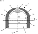
- FIG. 5 shows a variant embodiment of the invention.
- a hoop layer 15 is wound around the generally cylindrical central portion 8 of the liner 6 such that the first outer diameter D1 includes the hoop layer 15.
- the pressure vessel of the invention may be manufactured by means which are already well known in the art and which will not be described in further details here.
Landscapes
- Engineering & Computer Science (AREA)
- Mechanical Engineering (AREA)
- General Engineering & Computer Science (AREA)
- Filling Or Discharging Of Gas Storage Vessels (AREA)
Claims (18)
- Druckbehälter (4; 4'), aufweisend:- eine Auskleidung (6), die eine innere Flüssigkeitsspeicherkammer (3) definiert und aufweist:• einen allgemein zylindrischen mittleren Abschnitt (8) mit einem ersten Außendurchmesser D1 an einem ersten Längsende (8a),• ein erstes kuppelförmiges Längsende (12) mit einer Basis (12a) mit einem zweiten Außendurchmesser D2, wobei der zweite Außendurchmesser D2 kleiner als der erste Außendurchmesser D1 ist, und• einen ersten Zwischenabschnitt (13), der zwischen dem allgemein zylindrischen mittleren Abschnitt (8) und dem ersten kuppelförmigen Längsende (12) angeordnet ist und das erste Längsende (8a) des allgemein zylindrischen mittleren Abschnitts (8) mit der Basis (12a) des ersten kuppelförmigen Längsendes (12) verbindet,wobei das erste kuppelförmige Längsende (12) der Auskleidung (6) eine Kuppelkontur hat, die weniger konkav in Richtung der inneren Flüssigkeitsspeicherkammer (3) ist als ein kuppelförmiges Längsende mit einer geodätischen Kuppelkontur,- eine erste kuppelförmige Verstärkungsschale (16) mit einer Form, die komplementär zu der Form sowohl des ersten kuppelförmigen Längsendes (12) als auch des ersten Zwischenabschnitts (13) der Auskleidung (6) ist, wobei die erste kuppelförmige Verstärkungsschale (16) sowohl auf das erste kuppelförmige Längsende (12) als auch auf den ersten Zwischenabschnitt (13) der Auskleidung (6) aufgesetzt ist,- einen Vorsprung (14), und- eine äußere Verbundstruktur (20), die die Auskleidung (6) umschließt oder umhüllt, dadurch gekennzeichnet, dass die äußere Verbundstruktur (20) ferner die erste kuppelförmige Verstärkungsschale (16) umschließt oder umhüllt.
- Druckbehälter (4; 4') nach Anspruch 1, wobei die erste kuppelförmige Verstärkungsschale (16) eine Kuppelkontur aufweist, die zur inneren Flüssigkeitsspeicherkammer (3) hin weniger konkav ist als eine kuppelförmige Verstärkungsschale mit einer geodätischen Kuppelkontur.
- Druckbehälter (4; 4') nach einem der Ansprüche 1 bis 2, wobei der erste Zwischenabschnitt (13) der Auskleidung (6) eine äußere Umfangsfläche aufweist, die aus der Gruppe bestehend aus zylindrisch, kegelstumpfförmig, gekrümmt und Kombinationen davon ausgewählt ist.
- Druckbehälter (4; 4') nach Anspruch 3, wobei die äußere Umfangsfläche des ersten Zwischenabschnitts (13) eine Kombination aus einer ersten kegelstumpfförmigen Oberfläche (9) und einer ersten zylindrischen Oberfläche (11) ist.
- Druckbehälter (4; 4') nach Anspruch 4, wobei ein zwischen der ersten kegelstumpfförmigen Oberfläche (9) und der ersten zylindrischen Oberfläche (11) des ersten Zwischenabschnitts (13) gebildeter Winkel γ weniger als 15° und vorzugsweise weniger als 10° beträgt.
- Druckbehälter (4; 4') nach einem der Ansprüche 4 bis 5, wobei ein zwischen der ersten kegelstumpfförmigen Oberfläche (9) und einer äußeren Umfangsfläche des allgemein zylindrischen mittleren Abschnitts (8) gebildeter Winkel σ weniger als 15° und vorzugsweise weniger als 10° beträgt.
- Druckbehälter (4; 4') nach einem der vorhergehenden Ansprüche, wobei der größte Abstand zwischen der Kuppelkontur des ersten kuppelförmigen Längsendes (12) und der Kuppelkontur eines kuppelförmigen Längsendes mit einer geodätischen Kuppelkontur zwischen 0,1 % und 5 % des ersten Außendurchmessers D1, vorzugsweise zwischen 0,5 % und 2,5 % des ersten Außendurchmessers D1 beträgt.
- Druckbehälter (4; 4') nach einem der vorhergehenden Ansprüche, ferner mit einer Ringschicht (15), die um den allgemein zylindrischen mittleren Abschnitt (8) der Auskleidung (6) gewickelt ist, so dass der erste Außendurchmesser D1 die Ringschicht (15) einschließt.
- Druckbehälter (4; 4') nach einem der vorhergehenden Ansprüche, wobei- die Auskleidung (6) ferner aufweist:• einen dritten Außendurchmesser an einem zweiten, dem ersten Längsende (8a) gegenüberliegenden Längsende des allgemein zylindrischen mittleren Abschnitts (8),• ein zweites kuppelförmiges Längsende mit einer Basis mit einem vierten Außendurchmesser, wobei der vierte Außendurchmesser kleiner als der dritte Außendurchmesser ist,
und• einen zweiten Zwischenabschnitt, der zwischen dem allgemein zylindrischen mittleren Abschnitt (8) und dem zweiten kuppelförmigen Längsende angeordnet ist und das zweite Längsende des allgemein zylindrischen mittleren Abschnitts (8) mit der Basis des zweiten kuppelförmigen Längsendes verbindet,wobei das zweite kuppelförmige Längsende der Auskleidung (6) eine kuppelförmige Kontur aufweist, die weniger konkav in Richtung der inneren Fluidspeicherkammer ist als ein kuppelförmiges Längsende mit einer geodätischen Kuppelkontur,- der Druckbehälter ferner eine zweite kuppelförmige Verstärkungsschale mit einer Form aufweist, die komplementär zu der Form sowohl des zweiten kuppelförmigen Längsendes als auch des zweiten Zwischenabschnitts der Auskleidung (6) ist, wobei die zweite kuppelförmige Verstärkungsschale sowohl auf das zweite kuppelförmige Längsende als auch auf den zweiten Zwischenabschnitt der Auskleidung (6) aufgesetzt ist, und- die äußere Verbundstruktur (20), die die Auskleidung (6) und die beiden kuppelförmigen Verstärkungsschalen umschließt oder einhüllt. - Druckbehälter (4; 4') nach Anspruch 9, wobei der dritte Außendurchmesser ungefähr gleich dem ersten Außendurchmesser D1 ist.
- Druckbehälter (4; 4') nach einem der Ansprüche 9 bis 10, wobei der vierte Außendurchmesser etwa gleich dem zweiten Außendurchmesser D2 ist.
- Druckbehälter (4; 4') nach einem der Ansprüche 9 bis 11, wobei der zweite Zwischenabschnitt der Auskleidung (6) eine äußere Umfangsfläche aufweist, die aus der Gruppe bestehend aus zylindrisch, kegelstumpfförmig, gekrümmt und Kombinationen davon ausgewählt ist.
- Druckbehälter (4; 4') nach Anspruch 12, wobei die äußere Umfangsfläche des zweiten Zwischenabschnitts eine Kombination aus einer zweiten kegelstumpfförmigen Fläche und einer zweiten zylindrischen Fläche ist.
- Druckbehälter (4; 4') nach Anspruch 13, wobei ein zwischen der zweiten kegelstumpfförmigen Oberfläche und der zweiten zylindrischen Oberfläche des zweiten Zwischenbereichs gebildeter Winkel weniger als 15° und vorzugsweise weniger als 10° beträgt.
- Druckbehälter (4; 4') nach einem der Ansprüche 13 bis 14, wobei ein zwischen der zweiten kegelstumpfförmigen Oberfläche und einer äußeren Umfangsfläche des allgemein zylindrischen mittleren Abschnitts (8) gebildeter Winkel weniger als 15° und vorzugsweise weniger als 10° beträgt.
- Druckbehälter (4; 4') nach einem der Ansprüche 9 bis 15, wobei der größte Abstand zwischen der Kuppelkontur des zweiten kuppelförmigen Längsendes und der Kuppelkontur eines kuppelförmigen Längsendes mit einer geodätischen Kuppelkontur zwischen 0,1 % und 5 % des dritten Außendurchmessers, vorzugsweise zwischen 0,5 % und 2,5 % des dritten Außendurchmessers beträgt.
- Druckbehälter (4; 4') nach einem der Ansprüche 9 bis 16, ferner mit einer Ringschicht (15), die so um den allgemein zylindrischen mittleren Abschnitt (8) der Auskleidung (6) gewickelt ist, dass der dritte Außendurchmesser die Ringschicht (15) einschließt.
- Fahrzeug (2) mit einem Druckbehälter (4; 4') nach einem der vorhergehenden Ansprüche.
Applications Claiming Priority (2)
| Application Number | Priority Date | Filing Date | Title |
|---|---|---|---|
| LU102847A LU102847B1 (en) | 2021-07-16 | 2021-07-16 | Reinforced pressure vessel |
| PCT/EP2022/069564 WO2023285513A1 (en) | 2021-07-16 | 2022-07-13 | Reinforced pressure vessel |
Publications (3)
| Publication Number | Publication Date |
|---|---|
| EP4370820A1 EP4370820A1 (de) | 2024-05-22 |
| EP4370820B1 true EP4370820B1 (de) | 2025-03-05 |
| EP4370820C0 EP4370820C0 (de) | 2025-03-05 |
Family
ID=77838886
Family Applications (1)
| Application Number | Title | Priority Date | Filing Date |
|---|---|---|---|
| EP22741775.5A Active EP4370820B1 (de) | 2021-07-16 | 2022-07-13 | Verstärkter druckbehälter |
Country Status (7)
| Country | Link |
|---|---|
| US (1) | US20240263742A1 (de) |
| EP (1) | EP4370820B1 (de) |
| JP (1) | JP7675276B2 (de) |
| KR (1) | KR102744966B1 (de) |
| CN (1) | CN117651824B (de) |
| LU (1) | LU102847B1 (de) |
| WO (1) | WO2023285513A1 (de) |
Family Cites Families (20)
| Publication number | Priority date | Publication date | Assignee | Title |
|---|---|---|---|---|
| US3280567A (en) * | 1962-12-24 | 1966-10-25 | Us Rubber Co | Reinforced off-axis chamber ports |
| JP3382086B2 (ja) * | 1996-04-24 | 2003-03-04 | 本田技研工業株式会社 | 内燃エンジンの燃料供給装置 |
| JP2005113971A (ja) * | 2003-10-03 | 2005-04-28 | Fuji Heavy Ind Ltd | 耐圧容器用ライナ |
| JP2005273724A (ja) | 2004-03-23 | 2005-10-06 | Toyota Industries Corp | 圧力容器 |
| WO2010116528A1 (ja) | 2009-04-10 | 2010-10-14 | トヨタ自動車株式会社 | タンクおよびその製造方法 |
| DE102010020944A1 (de) * | 2010-05-19 | 2011-11-24 | Benteler Automobiltechnik Gmbh | Verfahren zur Herstellung eines Gasdruckbehälters und Gasdruckbehälter |
| JP2012246962A (ja) | 2011-05-26 | 2012-12-13 | Yachiyo Industry Co Ltd | 圧力容器 |
| JP6133707B2 (ja) | 2013-06-25 | 2017-05-24 | 株式会社Soken | 高圧タンクの検査方法、高圧タンクの検査システム、および、高圧タンク |
| DE102015222392A1 (de) * | 2015-11-13 | 2017-05-18 | Bayerische Motoren Werke Aktiengesellschaft | Druckbehälter mit einem Lastring, Kraftfahrzeug und Verfahren zur Herstellung eines Druckbehälters |
| JP2017144657A (ja) | 2016-02-18 | 2017-08-24 | トヨタ自動車株式会社 | ライナーの製造方法 |
| DE102017101627A1 (de) * | 2016-02-18 | 2017-08-24 | Toyota Jidosha Kabushiki Kaisha | Hochdrucktank und Verfahren zum Herstellen eines Hochdrucktanks |
| JP6683822B2 (ja) * | 2016-10-04 | 2020-04-22 | 八千代工業株式会社 | 圧力容器 |
| DE102017208492B4 (de) | 2017-05-19 | 2020-07-30 | Nproxx B.V. | Polkappenverstärkter Druckbehälter |
| KR102322373B1 (ko) | 2017-05-26 | 2021-11-05 | 현대자동차주식회사 | 후프층 및 헬리컬층이 와인딩된 고압용기 |
| JP2019002506A (ja) * | 2017-06-16 | 2019-01-10 | 株式会社Fts | 圧力容器 |
| JP7013857B2 (ja) * | 2017-12-27 | 2022-02-01 | トヨタ自動車株式会社 | タンク |
| JP7087907B2 (ja) | 2018-10-16 | 2022-06-21 | トヨタ自動車株式会社 | 高圧タンクおよび高圧タンクの製造方法 |
| JP7287293B2 (ja) * | 2020-01-30 | 2023-06-06 | トヨタ自動車株式会社 | 高圧タンクの製造方法 |
| JP7327271B2 (ja) * | 2020-05-01 | 2023-08-16 | トヨタ自動車株式会社 | 高圧タンクの製造方法 |
| EP4215796B1 (de) * | 2022-01-25 | 2025-04-30 | Indian Oil Corporation Limited | Druckbehälter zur speicherung von flüssigkeit |
-
2021
- 2021-07-16 LU LU102847A patent/LU102847B1/en active IP Right Grant
-
2022
- 2022-07-13 JP JP2024502146A patent/JP7675276B2/ja active Active
- 2022-07-13 KR KR1020247004306A patent/KR102744966B1/ko active Active
- 2022-07-13 CN CN202280050055.6A patent/CN117651824B/zh active Active
- 2022-07-13 EP EP22741775.5A patent/EP4370820B1/de active Active
- 2022-07-13 US US18/578,099 patent/US20240263742A1/en active Pending
- 2022-07-13 WO PCT/EP2022/069564 patent/WO2023285513A1/en not_active Ceased
Also Published As
| Publication number | Publication date |
|---|---|
| CN117651824B (zh) | 2024-06-21 |
| CN117651824A (zh) | 2024-03-05 |
| WO2023285513A1 (en) | 2023-01-19 |
| JP2024523739A (ja) | 2024-06-28 |
| EP4370820C0 (de) | 2025-03-05 |
| US20240263742A1 (en) | 2024-08-08 |
| EP4370820A1 (de) | 2024-05-22 |
| LU102847B1 (en) | 2023-01-16 |
| KR102744966B1 (ko) | 2024-12-20 |
| JP7675276B2 (ja) | 2025-05-12 |
| KR20240023446A (ko) | 2024-02-21 |
Similar Documents
| Publication | Publication Date | Title |
|---|---|---|
| EP3649393B1 (de) | Verbesserter druckbehälter | |
| KR20100090732A (ko) | 압축 가스용 용기, 용기 제조 방법 및 제조 설비 | |
| EP2433045A1 (de) | Hochdruckspeichergerät und -verfahren | |
| US11441732B2 (en) | Manufacturing method for high-pressure tank and high-pressure tank | |
| US11529780B2 (en) | Manufacturing method for high-pressure tank | |
| CN115769018A (zh) | 具有增强元件的复合材料压力容器 | |
| JP2024537870A (ja) | 気体バリア金属層を有するv型圧力容器 | |
| CN115243869A (zh) | 用于制造压力容器的方法和压力容器 | |
| EP4370820B1 (de) | Verstärkter druckbehälter | |
| EP4326526B1 (de) | Verfahren und systeme zum wickeln eines filaments um einen wickelträger | |
| EP4399433B1 (de) | Druckbehälter mit optimierter äusserer verbundstruktur | |
| EP4370313B1 (de) | Kuppelförmige verstärkungsschale für einen druckbehälter und verfahren zu deren herstellung | |
| US20240309994A1 (en) | Boss assembly for a pressure vessel |
Legal Events
| Date | Code | Title | Description |
|---|---|---|---|
| STAA | Information on the status of an ep patent application or granted ep patent |
Free format text: STATUS: UNKNOWN |
|
| STAA | Information on the status of an ep patent application or granted ep patent |
Free format text: STATUS: THE INTERNATIONAL PUBLICATION HAS BEEN MADE |
|
| PUAI | Public reference made under article 153(3) epc to a published international application that has entered the european phase |
Free format text: ORIGINAL CODE: 0009012 |
|
| STAA | Information on the status of an ep patent application or granted ep patent |
Free format text: STATUS: REQUEST FOR EXAMINATION WAS MADE |
|
| 17P | Request for examination filed |
Effective date: 20240214 |
|
| AK | Designated contracting states |
Kind code of ref document: A1 Designated state(s): AL AT BE BG CH CY CZ DE DK EE ES FI FR GB GR HR HU IE IS IT LI LT LU LV MC MK MT NL NO PL PT RO RS SE SI SK SM TR |
|
| GRAP | Despatch of communication of intention to grant a patent |
Free format text: ORIGINAL CODE: EPIDOSNIGR1 |
|
| STAA | Information on the status of an ep patent application or granted ep patent |
Free format text: STATUS: GRANT OF PATENT IS INTENDED |
|
| DAV | Request for validation of the european patent (deleted) | ||
| DAX | Request for extension of the european patent (deleted) | ||
| INTG | Intention to grant announced |
Effective date: 20241022 |
|
| GRAS | Grant fee paid |
Free format text: ORIGINAL CODE: EPIDOSNIGR3 |
|
| GRAA | (expected) grant |
Free format text: ORIGINAL CODE: 0009210 |
|
| STAA | Information on the status of an ep patent application or granted ep patent |
Free format text: STATUS: THE PATENT HAS BEEN GRANTED |
|
| AK | Designated contracting states |
Kind code of ref document: B1 Designated state(s): AL AT BE BG CH CY CZ DE DK EE ES FI FR GB GR HR HU IE IS IT LI LT LU LV MC MK MT NL NO PL PT RO RS SE SI SK SM TR |
|
| REG | Reference to a national code |
Ref country code: GB Ref legal event code: FG4D |
|
| REG | Reference to a national code |
Ref country code: CH Ref legal event code: EP |
|
| REG | Reference to a national code |
Ref country code: IE Ref legal event code: FG4D |
|
| REG | Reference to a national code |
Ref country code: DE Ref legal event code: R096 Ref document number: 602022011507 Country of ref document: DE |
|
| U01 | Request for unitary effect filed |
Effective date: 20250401 |
|
| U07 | Unitary effect registered |
Designated state(s): AT BE BG DE DK EE FI FR IT LT LU LV MT NL PT RO SE SI Effective date: 20250404 |
|
| PG25 | Lapsed in a contracting state [announced via postgrant information from national office to epo] |
Ref country code: RS Free format text: LAPSE BECAUSE OF FAILURE TO SUBMIT A TRANSLATION OF THE DESCRIPTION OR TO PAY THE FEE WITHIN THE PRESCRIBED TIME-LIMIT Effective date: 20250605 |
|
| PG25 | Lapsed in a contracting state [announced via postgrant information from national office to epo] |
Ref country code: ES Free format text: LAPSE BECAUSE OF FAILURE TO SUBMIT A TRANSLATION OF THE DESCRIPTION OR TO PAY THE FEE WITHIN THE PRESCRIBED TIME-LIMIT Effective date: 20250305 |
|
| PG25 | Lapsed in a contracting state [announced via postgrant information from national office to epo] |
Ref country code: NO Free format text: LAPSE BECAUSE OF FAILURE TO SUBMIT A TRANSLATION OF THE DESCRIPTION OR TO PAY THE FEE WITHIN THE PRESCRIBED TIME-LIMIT Effective date: 20250605 |
|
| PG25 | Lapsed in a contracting state [announced via postgrant information from national office to epo] |
Ref country code: HR Free format text: LAPSE BECAUSE OF FAILURE TO SUBMIT A TRANSLATION OF THE DESCRIPTION OR TO PAY THE FEE WITHIN THE PRESCRIBED TIME-LIMIT Effective date: 20250305 |
|
| PG25 | Lapsed in a contracting state [announced via postgrant information from national office to epo] |
Ref country code: GR Free format text: LAPSE BECAUSE OF FAILURE TO SUBMIT A TRANSLATION OF THE DESCRIPTION OR TO PAY THE FEE WITHIN THE PRESCRIBED TIME-LIMIT Effective date: 20250606 |
|
| U20 | Renewal fee for the european patent with unitary effect paid |
Year of fee payment: 4 Effective date: 20250730 |
|
| PG25 | Lapsed in a contracting state [announced via postgrant information from national office to epo] |
Ref country code: SM Free format text: LAPSE BECAUSE OF FAILURE TO SUBMIT A TRANSLATION OF THE DESCRIPTION OR TO PAY THE FEE WITHIN THE PRESCRIBED TIME-LIMIT Effective date: 20250305 |
|
| PG25 | Lapsed in a contracting state [announced via postgrant information from national office to epo] |
Ref country code: PL Free format text: LAPSE BECAUSE OF FAILURE TO SUBMIT A TRANSLATION OF THE DESCRIPTION OR TO PAY THE FEE WITHIN THE PRESCRIBED TIME-LIMIT Effective date: 20250305 |
|
| PG25 | Lapsed in a contracting state [announced via postgrant information from national office to epo] |
Ref country code: CZ Free format text: LAPSE BECAUSE OF FAILURE TO SUBMIT A TRANSLATION OF THE DESCRIPTION OR TO PAY THE FEE WITHIN THE PRESCRIBED TIME-LIMIT Effective date: 20250305 |
|
| PG25 | Lapsed in a contracting state [announced via postgrant information from national office to epo] |
Ref country code: SK Free format text: LAPSE BECAUSE OF FAILURE TO SUBMIT A TRANSLATION OF THE DESCRIPTION OR TO PAY THE FEE WITHIN THE PRESCRIBED TIME-LIMIT Effective date: 20250305 |
|
| PG25 | Lapsed in a contracting state [announced via postgrant information from national office to epo] |
Ref country code: IS Free format text: LAPSE BECAUSE OF FAILURE TO SUBMIT A TRANSLATION OF THE DESCRIPTION OR TO PAY THE FEE WITHIN THE PRESCRIBED TIME-LIMIT Effective date: 20250705 |
|
| PLBE | No opposition filed within time limit |
Free format text: ORIGINAL CODE: 0009261 |
|
| STAA | Information on the status of an ep patent application or granted ep patent |
Free format text: STATUS: NO OPPOSITION FILED WITHIN TIME LIMIT |
|
| REG | Reference to a national code |
Ref country code: CH Ref legal event code: L10 Free format text: ST27 STATUS EVENT CODE: U-0-0-L10-L00 (AS PROVIDED BY THE NATIONAL OFFICE) Effective date: 20260114 |
|
| 26N | No opposition filed |
Effective date: 20251208 |
|
| REG | Reference to a national code |
Ref country code: CH Ref legal event code: H13 Free format text: ST27 STATUS EVENT CODE: U-0-0-H10-H13 (AS PROVIDED BY THE NATIONAL OFFICE) Effective date: 20260224 |