EP4394193A1 - Vis - Google Patents
Vis Download PDFInfo
- Publication number
- EP4394193A1 EP4394193A1 EP23150062.0A EP23150062A EP4394193A1 EP 4394193 A1 EP4394193 A1 EP 4394193A1 EP 23150062 A EP23150062 A EP 23150062A EP 4394193 A1 EP4394193 A1 EP 4394193A1
- Authority
- EP
- European Patent Office
- Prior art keywords
- screw
- cutting elements
- sealing ring
- head
- disc
- Prior art date
- Legal status (The legal status is an assumption and is not a legal conclusion. Google has not performed a legal analysis and makes no representation as to the accuracy of the status listed.)
- Withdrawn
Links
Images


Classifications
-
- H—ELECTRICITY
- H01—ELECTRIC ELEMENTS
- H01R—ELECTRICALLY-CONDUCTIVE CONNECTIONS; STRUCTURAL ASSOCIATIONS OF A PLURALITY OF MUTUALLY-INSULATED ELECTRICAL CONNECTING ELEMENTS; COUPLING DEVICES; CURRENT COLLECTORS
- H01R4/00—Electrically-conductive connections between two or more conductive members in direct contact, i.e. touching one another; Means for effecting or maintaining such contact; Electrically-conductive connections having two or more spaced connecting locations for conductors and using contact members penetrating insulation
- H01R4/28—Clamped connections, spring connections
- H01R4/30—Clamped connections, spring connections utilising a screw or nut clamping member
- H01R4/304—Clamped connections, spring connections utilising a screw or nut clamping member having means for improving contact
-
- F—MECHANICAL ENGINEERING; LIGHTING; HEATING; WEAPONS; BLASTING
- F16—ENGINEERING ELEMENTS AND UNITS; GENERAL MEASURES FOR PRODUCING AND MAINTAINING EFFECTIVE FUNCTIONING OF MACHINES OR INSTALLATIONS; THERMAL INSULATION IN GENERAL
- F16B—DEVICES FOR FASTENING OR SECURING CONSTRUCTIONAL ELEMENTS OR MACHINE PARTS TOGETHER, e.g. NAILS, BOLTS, CIRCLIPS, CLAMPS, CLIPS OR WEDGES; JOINTS OR JOINTING
- F16B43/00—Washers or equivalent devices; Other devices for supporting bolt-heads or nuts
- F16B43/001—Washers or equivalent devices; Other devices for supporting bolt-heads or nuts for sealing or insulation
-
- H—ELECTRICITY
- H01—ELECTRIC ELEMENTS
- H01R—ELECTRICALLY-CONDUCTIVE CONNECTIONS; STRUCTURAL ASSOCIATIONS OF A PLURALITY OF MUTUALLY-INSULATED ELECTRICAL CONNECTING ELEMENTS; COUPLING DEVICES; CURRENT COLLECTORS
- H01R4/00—Electrically-conductive connections between two or more conductive members in direct contact, i.e. touching one another; Means for effecting or maintaining such contact; Electrically-conductive connections having two or more spaced connecting locations for conductors and using contact members penetrating insulation
- H01R4/26—Connections in which at least one of the connecting parts has projections which bite into or engage the other connecting part in order to improve the contact
-
- F—MECHANICAL ENGINEERING; LIGHTING; HEATING; WEAPONS; BLASTING
- F16—ENGINEERING ELEMENTS AND UNITS; GENERAL MEASURES FOR PRODUCING AND MAINTAINING EFFECTIVE FUNCTIONING OF MACHINES OR INSTALLATIONS; THERMAL INSULATION IN GENERAL
- F16B—DEVICES FOR FASTENING OR SECURING CONSTRUCTIONAL ELEMENTS OR MACHINE PARTS TOGETHER, e.g. NAILS, BOLTS, CIRCLIPS, CLAMPS, CLIPS OR WEDGES; JOINTS OR JOINTING
- F16B2200/00—Constructional details of connections not covered for in other groups of this subclass
- F16B2200/93—Fastener comprising feature for establishing a good electrical connection, e.g. electrostatic discharge or insulation feature
Definitions
- the sealing ring is designed to be circumferential. This means that the sealing ring has no interruptions. In this embodiment, it is advantageously possible that the sealing effect of the sealing ring can be optimized.
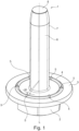
- the screw 1 extends along a longitudinal axis L from a head 2 with a force application point to a front end 8 or a tip 8.
- the tip 8 is flattened in this example, but it can alternatively be tapered.
- the screw 1 also has a shaft 6 with a thread 7.
- the shaft 6 tapers in the front part up to the front end 8.
- the disk 3 has a thickness which in this embodiment is smaller than the thickness of the head 2.
- the sealing ring 4 has a height which is less than the thickness of the disk 3.
- the sealing ring 4 is designed to be completely circumferential in the radial direction, which means that there are no gaps in the sealing ring 4.
- the disc 3 with the sealing ring 4 are rotationally symmetrical with respect to the longitudinal axis L.
- the disc 3 is designed as a circular cylindrical disc
- the sealing ring 4 is designed as a circular hollow ring which runs around the longitudinal axis L.
- six cutting elements 5 are arranged equidistantly, i.e. at the same distance from one another, on the sealing ring 4, the height of which is less than 60% of the height of the sealing ring 4.
- the cutting elements 5 are wart-shaped. They have a substantially round base and extend conically towards their highest point.
- the length of an angle w over which one of the cutting elements 5 extends in the radial direction is at least 5°.
- the screw 1 is screwed into a contact material and penetrates a surface protective coating.
- the cutting elements 5 the surface protective coating and thus create an improved electrical contact.
- the sealing ring 4 enables the sealing of the contact of liquid and so on.
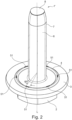
- this second embodiment has six trapezoidal cutting elements 51. These trapezoidal cutting elements 51 are essentially trapezoidal in cross section. The cutting elements 51 extend over a length of an angle w2 in the radial direction onto the sealing ring 4.
- the cutting elements 51 extend over a length L of the angle w2 of at least 5°.
- Figure 3 shows a screw 1" according to a third embodiment of the invention in a side view.
- this third embodiment has six wave-shaped cutting elements 52. These wave-shaped cutting elements 52 are arranged evenly from one another on the sealing ring 4. Wave-shaped means that the height of the cutting elements 52 increases evenly and then decreases evenly again after a maximum height.
- the maxima of the cutting elements 52 which are adjacent are spaced apart from each other at an angle w3. In this case, with six wave-shaped cutting elements 52, the distance between adjacent cutting elements 52 is 60°.
- Figure 4a shows schematically a cross-sectional view of the screw 1 according to the first embodiment in a composite with a contacting material 9 with a surface protection coating 10.
- the cutting elements 5 cut through the surface protection coating 10 and thereby ensure contact between the screw and the contacting material 9.
Landscapes
- Engineering & Computer Science (AREA)
- General Engineering & Computer Science (AREA)
- Mechanical Engineering (AREA)
- Gasket Seals (AREA)
Priority Applications (1)
| Application Number | Priority Date | Filing Date | Title |
|---|---|---|---|
| EP23150062.0A EP4394193A1 (fr) | 2023-01-02 | 2023-01-02 | Vis |
Applications Claiming Priority (1)
| Application Number | Priority Date | Filing Date | Title |
|---|---|---|---|
| EP23150062.0A EP4394193A1 (fr) | 2023-01-02 | 2023-01-02 | Vis |
Publications (1)
| Publication Number | Publication Date |
|---|---|
| EP4394193A1 true EP4394193A1 (fr) | 2024-07-03 |
Family
ID=84785428
Family Applications (1)
| Application Number | Title | Priority Date | Filing Date |
|---|---|---|---|
| EP23150062.0A Withdrawn EP4394193A1 (fr) | 2023-01-02 | 2023-01-02 | Vis |
Country Status (1)
| Country | Link |
|---|---|
| EP (1) | EP4394193A1 (fr) |
Citations (4)
| Publication number | Priority date | Publication date | Assignee | Title |
|---|---|---|---|---|
| US3626357A (en) * | 1970-09-02 | 1971-12-07 | Colin David Kindell | Electrical connecting washer |
| US4220188A (en) * | 1978-07-10 | 1980-09-02 | Russell, Burdsall & Ward Corporation | Locking fastener |
| CN102741569A (zh) * | 2009-09-17 | 2012-10-17 | 米克罗·华尔特 | 具有底面刀具和容器的螺钉 |
| DE102019200240A1 (de) * | 2019-01-10 | 2020-07-16 | Arnold Umformtechnik Gmbh & Co. Kg | Verbindungsmittel zur Herstellung einer elektrisch leitenden Verbindung, Verfahren und Anordnung |
-
2023
- 2023-01-02 EP EP23150062.0A patent/EP4394193A1/fr not_active Withdrawn
Patent Citations (4)
| Publication number | Priority date | Publication date | Assignee | Title |
|---|---|---|---|---|
| US3626357A (en) * | 1970-09-02 | 1971-12-07 | Colin David Kindell | Electrical connecting washer |
| US4220188A (en) * | 1978-07-10 | 1980-09-02 | Russell, Burdsall & Ward Corporation | Locking fastener |
| CN102741569A (zh) * | 2009-09-17 | 2012-10-17 | 米克罗·华尔特 | 具有底面刀具和容器的螺钉 |
| DE102019200240A1 (de) * | 2019-01-10 | 2020-07-16 | Arnold Umformtechnik Gmbh & Co. Kg | Verbindungsmittel zur Herstellung einer elektrisch leitenden Verbindung, Verfahren und Anordnung |
Similar Documents
| Publication | Publication Date | Title |
|---|---|---|
| EP0217053B1 (fr) | Ancre à expansion | |
| DE102009000891B4 (de) | Verfahren und Gewindewerkzeug, jeweils zur Ausformung eines lnnengewindes an einem Grundkörper | |
| DE6921404U (de) | Selbstsicherndes befestigungselement | |
| EP1031742B1 (fr) | Vis à tête conique | |
| DE2642929A1 (de) | Elektrischer verbinder | |
| EP3267913A1 (fr) | Plaque osseuse comprenant une vis osseuse | |
| DE102013103463A1 (de) | Werkzeug, Schraube und System zur Übertragung eines Antriebsmoments | |
| DE69607462T2 (de) | Selbstsichernde Mutter | |
| EP3401557B1 (fr) | Vis à bois | |
| EP0939235A1 (fr) | Vis | |
| WO2015124365A1 (fr) | Dispositif de protection contre la foudre | |
| WO2012019600A1 (fr) | Liaison vissée électroconductrice et vis spéciale pour une telle liaison vissée | |
| EP3071355B1 (fr) | Fraise à chanfreiner | |
| DE2018755C2 (de) | Hochspannungs-Stapelkondensator und Verfahren zu seiner Herstellung | |
| DE102014213610A1 (de) | Gewindeeinsatz und diesen enthaltendes Bauteil | |
| DE102012108779A1 (de) | Profilverbindung | |
| EP3034893B1 (fr) | Vis-cheville | |
| EP4394193A1 (fr) | Vis | |
| DE2306891B1 (de) | Ringförmiges Kontaktelement | |
| DE102013226768A1 (de) | Mutter | |
| DE102010041165A1 (de) | Bohrschraube | |
| EP0211802B1 (fr) | Douille de cheville | |
| DE2451853A1 (de) | Koaxialleitungsabschnitt mit einer isolierstuetze | |
| WO2020144279A1 (fr) | Moyen de connexion pour réaliser une connexion électriquement conductrice, procédé et dispositif | |
| DE3637626C2 (de) | Verfahren zum Festlegen eines Metallstifts innerhalb eines keramischen Isolierkörpers |
Legal Events
| Date | Code | Title | Description |
|---|---|---|---|
| PUAI | Public reference made under article 153(3) epc to a published international application that has entered the european phase |
Free format text: ORIGINAL CODE: 0009012 |
|
| STAA | Information on the status of an ep patent application or granted ep patent |
Free format text: STATUS: THE APPLICATION HAS BEEN PUBLISHED |
|
| AK | Designated contracting states |
Kind code of ref document: A1 Designated state(s): AL AT BE BG CH CY CZ DE DK EE ES FI FR GB GR HR HU IE IS IT LI LT LU LV MC ME MK MT NL NO PL PT RO RS SE SI SK SM TR |
|
| STAA | Information on the status of an ep patent application or granted ep patent |
Free format text: STATUS: THE APPLICATION IS DEEMED TO BE WITHDRAWN |
|
| 18D | Application deemed to be withdrawn |
Effective date: 20250104 |