EP4397615B1 - Aufzugsanlage - Google Patents
Aufzugsanlage Download PDFInfo
- Publication number
- EP4397615B1 EP4397615B1 EP23150392.1A EP23150392A EP4397615B1 EP 4397615 B1 EP4397615 B1 EP 4397615B1 EP 23150392 A EP23150392 A EP 23150392A EP 4397615 B1 EP4397615 B1 EP 4397615B1
- Authority
- EP
- European Patent Office
- Prior art keywords
- guide rail
- solid
- solid guide
- flange portion
- elevator system
- Prior art date
- Legal status (The legal status is an assumption and is not a legal conclusion. Google has not performed a legal analysis and makes no representation as to the accuracy of the status listed.)
- Active
Links
Images


Classifications
-
- B—PERFORMING OPERATIONS; TRANSPORTING
- B66—HOISTING; LIFTING; HAULING
- B66B—ELEVATORS; ESCALATORS OR MOVING WALKWAYS
- B66B7/00—Other common features of elevators
- B66B7/02—Guideways; Guides
- B66B7/022—Guideways; Guides with a special shape
Definitions
- the present invention relates to an elevator system comprising elevator rails and more particularly, solid guide rails having more than one guide contours for guiding elevator cars and counterweights of the elevator system.
- elevators are an essential part of multi-story buildings, such as commercial buildings or residential buildings, for transporting persons/goods between different floors.
- elevators are available in different configurations which can be deployed in the building based on factors, such as type of passengers, traffic flux, building dimensions, elevator location, and car arrangement.
- a moving body i.e., an elevator car or a counterweight
- each moving body is guided by two elevator rails which are often attached independently of one another to different shaft walls.
- an elevator type is usually used in which the elevator car is held by rope or belt-like suspension elements and displaced within an elevator shaft by moving the suspension elements by means of a drive machine.
- a counterweight is usually attached to an opposite end of the suspension elements. This counterweight has at least the same mass as the elevator car.
- the mass of the counterweight exceeds that of the elevator car by half of the payload to be transported permissibly by the elevator car.
- a plurality of counterweights and/or a plurality of elevator cars can also be provided in an elevator system.
- EP0611724A1 shows an elevator system comprising a guide system guiding together an elevator car and a counterweight, wherein the guide system is a solid guide rail comprising at least one flange portion and at least one web portion.
- the elevator system 1 having a guide system includes at least two counterweights 5 and a car 4.
- Each of the first solid guide rail 2 and the second solid guide rail 2' individually guides a counterweight 5 from the at least two counterweights 5.
- each of the first solid guide rail 2 and the second solid guide rail 2' collectively guide the car 4.
- each of the first solid guide rail 2 and the second solid guide rail 2' guide an associated counterweight 5 via two ends 8a of the second flange portion 8.
- each of the first solid guide rail 2 and the second solid guide rail 2 collectively guide the car 4 via two ends 8a' of the first flange portion 8'.
- the two ends 8a' of the first flange portion 8' and the two ends 8a of the second flange portion 8 define the four guide contours 6a, 6b, 10. At least one end 8a' from the two ends 8a' of the first flange portion 8' is the braking contour 10.
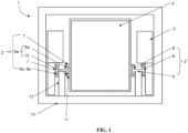
- FIG. 2 illustrates a top view of a building depicting an elevator system 1 with a T-shaped solid guide rail 2, according to an embodiment of the present invention.
- the T-shaped solid guide rail 2 includes a single flange portion 8 perpendicularly oriented to a single web portion 9.
- the flange portion 8 and the web portion 9 collectively define the T-shaped cross section or T-shaped profile.
- An end 9a of the web portion 9 and at least one of the ends 8a and preferably each end 8a of the flange portion 8 defines the plurality of guide contours 6a, 6b, 10.
- at least one of the plurality of guide contours 6a, 6b, 10 is defined as a braking contour 10.
- the braking contour 10 is formed on the end 9a of the web portion 9 proximal to the car 4 of the elevator system 1.
- the braking contour 10 serves as a braking surface for a safety brake of the car 4.
- the braking contour 10 is shown as the end 9a of the web portion 9, it must be appreciated that other configurations may be envisioned.
- the flange portion 8 may be positioned to engage with the guide shoe 7 of the car 4 instead of the guide shoe 7' of the counterweight 5 as shown in Figure 2 . In such an arrangement, one of the ends 8a of the flange portion 8 may be defined as the braking contour 10.
- each of the first solid guide rail 2 and the second solid guide rail 2' guide an associated counterweight 5 via the two ends 8a of the flange portion.
- Each of the first solid guide rail 2 and the second solid guide rail 2' collectively guide the car 4 via the end 9a of the web portion 9.
- the two ends 8a of the flange portion 8 define two guide contours 6b and the end 9a of the web portion 9 is the guide contour 6a defined as the braking contour 10 from among the plurality of guide contours 6a, 6b, 10.
- one or more surface machining operations comprising for example milling may be employed to provide a geometrically defined surface having a rectangular shape for guidance.
- the first web portion 9, from the pair of web portions 9, is spaced apart from a second web portion 9'.
- the flange portion 8 and the pair of web portions 9, 9' collectively define a double T-shaped cross section or double T-shaped profile.
- Each end 8a of the flange portion 8 and each end 9a, 9a' of the pair of web portions 9, 9' define the plurality of guide contours 6a, 6b, 10.
- each of the first solid guide rail 2 and the second solid guide rail 2' (not shown) guide an associated counterweight 5 via two ends 8a of a flange portion 8.
- Each of the first solid guide rail 2 and the second solid guide rail 2' collectively guide the car 4 via ends 9a, 9a' of a pair of web portions 9, 9'.
- the two ends 8a of the flange portion 8 and the ends 9a, 9a' of the pair of web portions 9, 9' define four guide contours 6a, 6b, 10.
- at least one end 9a' from the ends 9a, 9a' of the pair of web portions 9, 9', for example, the end 9a' of the second web portion 9' is the braking contour 10 which serves as the braking surface for the safety brake 11.
- the solid guide rails 2 are manufactured using generally known techniques for manufacturing conventional I-beam, T-beam, or double T beam profiles. These include but are not limited to hot rolling, cold rolling, extrusion techniques, and the like. Alternatively, welding techniques, for example, spot-welding, etc., may be used. Since I-beams, T-beams, or double T beams are widely used in the construction industry and are readily available in a variety of standard sizes, the ease of assembly or installation is considerably improved. Moreover, in the event of repair or maintenance requiring replacement of the solid guide rail, the solid guide rail of a suitable size and shape can be readily procured.
- the elevator system 1 since the elevator system 1 utilizes only two solid guide rails 2, the geometrical and construction requirements of only the front wall 13 of the four shaft walls may be subject to a higher degree of precision.
- the structural precision of the other shaft walls can be lower.
- All other shaft walls can be made from materials that are unsuitable for fastening the elevator system 1, also from significantly weaker materials. This feature allows increased flexibility while selecting construction materials thereby further reducing overall construction costs.
- the elevator system 1, according to the invention has the advantage that it is sufficient to mount only two instead of four or even six solid guide rails 2. This is advantageous because by using two counterweights 5, the base surface of the shaft can be optimally utilized. Finally, since the elevator rail 2 is designed as a solid guide rail 2 to be sturdy, the solid profile in comparison to existing hollow rails can better withstand external pressure forces.
Landscapes
- Lift-Guide Devices, And Elevator Ropes And Cables (AREA)
Claims (13)
- Aufzugssystem (1), das ein Führungssystem aufweist, wobei das Aufzugssystem (1) mindestens zwei Gegengewichte (5) und eine Kabine (4) umfasst, wobei das Führungssystem eine erste massive Führungsschiene (2) und eine zweite massive Führungsschiene (2') umfasst, die individuell ein Gegengewicht (5) von den mindestens zwei Gegengewichten (5) führen, und jede der ersten massiven Führungsschiene (2) und der zweiten massiven Führungsschiene (2') gemeinsam die Kabine (4) führen, wobei die erste massive Führungsschiene (2) und die zweite massive Führungsschiene (2') jeweils eine Vielzahl von Führungskonturen (6a, 6b, 10) umfassen, die ausgelegt sind, um mit dem Gegengewicht (5) und der Kabine (4) in Eingriff zu kommen, dadurch gekennzeichnet, dass die massiven Führungsschienen (2, 2') mindestens einen Flanschabschnitt (8) und mindestens einen Stegabschnitt (9) aufweisen, und dass die Vielzahl von Führungskonturen (6a, 6b, 10) an mindestens einem von dem Flanschabschnitt (8) und dem Stegabschnitt (9) definiert ist.
- Aufzugssystem (1) nach Anspruch 1, wobei jede der ersten massiven Führungsschiene (2) und der zweiten massiven Führungsschiene (2') ein Paar von Flanschabschnitten (8, 8') umfasst, die parallel zueinander angeordnet und durch einen Stegabschnitt (9) getrennt sind, wobei das Paar von Flanschabschnitten (8) senkrecht in Bezug auf den Stegabschnitt (9) ausgerichtet ist.
- Aufzugssystem (1) nach Anspruch 1 oder 2, wobei jedes Ende (8a) des Paares von Flanschabschnitten (8) die Vielzahl von Führungskonturen (6a, 6b, 10) definiert.
- Aufzugssystem (1) nach Anspruch 1, wobei die erste massive Führungsschiene (2) und die zweite massive Führungsschiene (2') jeweils einen Flanschabschnitt (8) umfassen, der senkrecht zu dem Stegabschnitt (9) ausgerichtet ist, wobei der Flanschabschnitt (8) und der Stegabschnitt (9) zusammen einen T-förmigen Querschnitt definieren.
- Aufzugssystem (1) nach einem der Ansprüche 1 bis 4, wobei ein Ende (9a) des Stegabschnitts (9) und mindestens eines der Enden (8a) und vorzugsweise jedes Ende (8a) des Flanschabschnitts (8) die Vielzahl der Führungskonturen (6a, 6b, 10) definieren.
- Aufzugssystem (1) nach Anspruch 1, wobei jede der ersten massiven Führungsschiene (2) und der zweiten massiven Führungsschiene (2') umfasst:ein Paar von Stegabschnitten (9); undden Flanschabschnitt (8), der senkrecht in Bezug auf jeden des Paares von Stegabschnitten (9) ausgerichtet ist,wobei ein erster Stegabschnitt (9) des Paares von Stegabschnitten (9) von einem zweiten Stegabschnitt (9) beabstandet ist, der Flanschabschnitt (8) und das Paar von Stegabschnitten (9) gemeinsam einen doppelten T-förmigen Querschnitt definieren und jedes Ende (8a) des Flanschabschnitts (8) und jedes Ende (9a) des Paares von Stegabschnitten (9) die Vielzahl von Führungskonturen (6a, 6b, 10) definieren.
- Aufzugssystem (1) nach einem der Ansprüche 1 bis 6, wobei mindestens eine der Vielzahl von Führungskonturen (6a, 6b, 10) als Bremskontur (10) definiert und an mindestens einem Ende (8a) des mindestens einen Flanschabschnitts (8) ausgebildet ist, wobei die Bremskontur (10) als eine Bremsoberfläche für eine Sicherheitsbremse (11) der Kabine (4) dient, oder
wobei mindestens eine der Vielzahl von Führungskonturen (6a, 6b, 10) als Bremskontur (10) definiert und an einem Ende (9a) des mindestens einen Stegabschnitts (9) ausgebildet ist, wobei die Bremskontur (10) als Bremsoberfläche für die Sicherheitsbremse (11) der Kabine (4) dient. - Aufzugssystem (1) nach den Ansprüchen 1 bis 7, wobei die erste massive Führungsschiene (2) und die zweite massive Führungsschiene (2') ferner jeweils mindestens eine Bügelbefestigungskontur umfassen, an der mindestens ein Bügel (12) vertikal beweglich befestigt werden kann.
- Aufzugssystem (1) nach den Ansprüchen 1 bis 8, umfassend eine Vielzahl von Bügel (12), die jeweils an einer der ersten massiven Führungsschiene (2) und der zweiten massiven Führungsschiene (2) befestigt sind, wobei die Vielzahl von Bügel (12) die erste massive Führungsschiene (2) und die zweite massive Führungsschiene (2) direkt oder indirekt mit einer Schachtwand verbindet.
- Aufzugssystem (1) nach Anspruch 9, wobei die Vielzahl von Bügel (12) mit einer Schachtwand aus einer Vielzahl von Schachtwänden verbunden ist, wobei die Schachtwand eine Vorderwand (13) ist, in die Bodenöffnungen integriert sind.
- Aufzugssystem (1) nach Anspruch 1, wobei:jede der ersten massiven Führungsschiene (2) und der zweiten massiven Führungsschiene (2') ein zugeordnetes Gegengewicht (5) über zwei Enden (8a) eines ersten Flanschabschnitts (8) führen und jede der ersten massiven Führungsschiene (2) und der zweiten massiven Führungsschiene (2') gemeinsam die Kabine (4) über zwei Enden (8a') eines zweiten Flanschabschnitts (8') führen,wobei die beiden Enden (8a) des ersten Flanschabschnitts (8) und die beiden Enden (8a') des zweiten Flanschabschnitts (8') vier Führungskonturen (6a, 6b, 10) definieren, und mindestens ein Ende (8a') der beiden Enden (8a') des zweiten Flanschabschnitts (8') eine Bremskontur (10) ist.
- Aufzugssystem (1) nach Anspruch 11, wobei:die erste massive Führungsschiene (2) und die zweite massive Führungsschiene (2') jeweils ein zugeordnetes Gegengewicht (5) über zwei Enden (8a) eines Flanschabschnitts (8) führen, und jede der ersten massiven Führungsschiene (2) und der zweiten massiven Führungsschiene (2') gemeinsam die Kabine (4) über ein Ende (9a) eines Stegabschnitts (9) führen,wobei die beiden Enden (8a) des Flanschabschnitts (8) zwei Führungskonturen (6b) definieren und das Ende (9a) des Stegabschnitts (9) eine Bremskontur (10) aus der Vielzahl der Führungskonturen (6a, 6b, 10) definiert.
- Aufzugssystem (1) nach Anspruch 12, wobei:die erste massive Führungsschiene (2) und die zweite massive Führungsschiene (2') jeweils ein zugeordnetes Gegengewicht (5) über zwei Enden (8a) eines Flanschabschnitts (8) führen, und jede der ersten massiven Führungsschiene (2) und der zweiten massiven Führungsschiene (2') gemeinsam die Kabine (4) über Enden (9a, 9a') eines Paares von Stegabschnitten (9, 9') führen,wobei die beiden Enden (8a) des Flanschabschnitts (8) und die Enden (9a, 9a') des Paares von Stegabschnitten (9, 9') vier Führungskonturen (6a, 6b, 10) definieren, und mindestens ein Ende (9a') der Enden (9a, 9a') des Paares von Stegabschnitten (9, 9') eine Bremskontur (10) ist.
Priority Applications (1)
| Application Number | Priority Date | Filing Date | Title |
|---|---|---|---|
| EP23150392.1A EP4397615B1 (de) | 2023-01-05 | 2023-01-05 | Aufzugsanlage |
Applications Claiming Priority (1)
| Application Number | Priority Date | Filing Date | Title |
|---|---|---|---|
| EP23150392.1A EP4397615B1 (de) | 2023-01-05 | 2023-01-05 | Aufzugsanlage |
Publications (2)
| Publication Number | Publication Date |
|---|---|
| EP4397615A1 EP4397615A1 (de) | 2024-07-10 |
| EP4397615B1 true EP4397615B1 (de) | 2025-06-25 |
Family
ID=84829816
Family Applications (1)
| Application Number | Title | Priority Date | Filing Date |
|---|---|---|---|
| EP23150392.1A Active EP4397615B1 (de) | 2023-01-05 | 2023-01-05 | Aufzugsanlage |
Country Status (1)
| Country | Link |
|---|---|
| EP (1) | EP4397615B1 (de) |
Citations (1)
| Publication number | Priority date | Publication date | Assignee | Title |
|---|---|---|---|---|
| WO2020127787A1 (de) * | 2018-12-20 | 2020-06-25 | Inventio Ag | Aufzugsschiene |
Family Cites Families (5)
| Publication number | Priority date | Publication date | Assignee | Title |
|---|---|---|---|---|
| FR2242318A1 (en) * | 1973-09-03 | 1975-03-28 | Durand Francois | Lift using rolled steel beam as guide track - lift cabin and counterweights run along opposite sides of beam |
| DE9302119U1 (de) * | 1993-02-15 | 1993-04-01 | C. Haushahn GmbH & Co, 7000 Stuttgart | Führungsvorrichtung für Aufzüge |
| DE4423412A1 (de) * | 1994-07-05 | 1996-04-11 | Foerder Weber & Systemtechnik | Führungseinrichtung |
| JP3910667B2 (ja) * | 1996-10-31 | 2007-04-25 | オーチス エレベータ カンパニー | エレベーターの合体型ガイドレール |
| CN114829285B (zh) | 2019-12-19 | 2025-04-11 | 因温特奥股份公司 | 用于电梯设备的驱动系统、电梯设备和用于将驱动器装配在电梯设备的支撑元件上的方法 |
-
2023
- 2023-01-05 EP EP23150392.1A patent/EP4397615B1/de active Active
Patent Citations (1)
| Publication number | Priority date | Publication date | Assignee | Title |
|---|---|---|---|---|
| WO2020127787A1 (de) * | 2018-12-20 | 2020-06-25 | Inventio Ag | Aufzugsschiene |
Also Published As
| Publication number | Publication date |
|---|---|
| EP4397615A1 (de) | 2024-07-10 |
Similar Documents
| Publication | Publication Date | Title |
|---|---|---|
| CN113242836B (zh) | 电梯轨 | |
| EP2571800B1 (de) | Führungsschiene aus blech für ein aufzugssystem | |
| EP3498650B1 (de) | Pneumatische vakuumaufzugskabinenführungen | |
| AU2015326986B2 (en) | Lift system having individually driven cars and a closed track | |
| EP3766817B1 (de) | Aufzugsführungsschiene | |
| KR102042927B1 (ko) | 리니어 모터 방식 엘리베이터의 비상 정지 장치 | |
| US11840424B2 (en) | Running system for elevator, and multi-car elevator running system | |
| EP4397615B1 (de) | Aufzugsanlage | |
| US5725074A (en) | Apparatus for supporting and guiding an elevator | |
| US20180354754A1 (en) | Elevator system | |
| WO2010083002A2 (en) | Elevator door sill | |
| CN113242837B (zh) | 具有脱轨保护件的电梯设备 | |
| JP2022549964A (ja) | ダブルデッキエレベータ用エレベータかご | |
| EP0626335B1 (de) | Mittels Linearmotor angetriebener Aufzug und dessen Führungsschiene | |
| US20020170790A1 (en) | Elevator safety brake | |
| US12479699B2 (en) | Roller guide shoe for guiding an elevator car of an elevator | |
| EP3752442B1 (de) | Verfahren und vorrichtung zur aufzugsinstallation | |
| EP1567440B1 (de) | Scheibenkonstruktion für ein aufzugssystem | |
| WO2015189652A1 (en) | Elevator system | |
| HK40047713A (en) | Lift rail | |
| CN218088479U (zh) | 一种应用于乘用电梯轿厢架的减震弹簧底梁 | |
| US20250042694A1 (en) | Elevator system and method for operating an elevator system | |
| EP1798187B1 (de) | Rollenkonstruktion für ein Aufzugsystem | |
| WO1996000183A1 (en) | Procedure for the manufacture of elevator guide rails | |
| JP2002060159A (ja) | ガイドレール |
Legal Events
| Date | Code | Title | Description |
|---|---|---|---|
| PUAI | Public reference made under article 153(3) epc to a published international application that has entered the european phase |
Free format text: ORIGINAL CODE: 0009012 |
|
| STAA | Information on the status of an ep patent application or granted ep patent |
Free format text: STATUS: THE APPLICATION HAS BEEN PUBLISHED |
|
| AK | Designated contracting states |
Kind code of ref document: A1 Designated state(s): AL AT BE BG CH CY CZ DE DK EE ES FI FR GB GR HR HU IE IS IT LI LT LU LV MC ME MK MT NL NO PL PT RO RS SE SI SK SM TR |
|
| STAA | Information on the status of an ep patent application or granted ep patent |
Free format text: STATUS: REQUEST FOR EXAMINATION WAS MADE |
|
| 17P | Request for examination filed |
Effective date: 20250108 |
|
| GRAP | Despatch of communication of intention to grant a patent |
Free format text: ORIGINAL CODE: EPIDOSNIGR1 |
|
| STAA | Information on the status of an ep patent application or granted ep patent |
Free format text: STATUS: GRANT OF PATENT IS INTENDED |
|
| GRAS | Grant fee paid |
Free format text: ORIGINAL CODE: EPIDOSNIGR3 |
|
| INTG | Intention to grant announced |
Effective date: 20250422 |
|
| GRAA | (expected) grant |
Free format text: ORIGINAL CODE: 0009210 |
|
| STAA | Information on the status of an ep patent application or granted ep patent |
Free format text: STATUS: THE PATENT HAS BEEN GRANTED |
|
| AK | Designated contracting states |
Kind code of ref document: B1 Designated state(s): AL AT BE BG CH CY CZ DE DK EE ES FI FR GB GR HR HU IE IS IT LI LT LU LV MC ME MK MT NL NO PL PT RO RS SE SI SK SM TR |
|
| REG | Reference to a national code |
Ref country code: GB Ref legal event code: FG4D |
|
| REG | Reference to a national code |
Ref country code: CH Ref legal event code: EP |
|
| REG | Reference to a national code |
Ref country code: CH Ref legal event code: EP |
|
| REG | Reference to a national code |
Ref country code: IE Ref legal event code: FG4D |
|
| REG | Reference to a national code |
Ref country code: DE Ref legal event code: R096 Ref document number: 602023004152 Country of ref document: DE |
|
| PG25 | Lapsed in a contracting state [announced via postgrant information from national office to epo] |
Ref country code: FI Free format text: LAPSE BECAUSE OF FAILURE TO SUBMIT A TRANSLATION OF THE DESCRIPTION OR TO PAY THE FEE WITHIN THE PRESCRIBED TIME-LIMIT Effective date: 20250625 |
|
| REG | Reference to a national code |
Ref country code: LT Ref legal event code: MG9D |
|
| PG25 | Lapsed in a contracting state [announced via postgrant information from national office to epo] |
Ref country code: NO Free format text: LAPSE BECAUSE OF FAILURE TO SUBMIT A TRANSLATION OF THE DESCRIPTION OR TO PAY THE FEE WITHIN THE PRESCRIBED TIME-LIMIT Effective date: 20250925 Ref country code: GR Free format text: LAPSE BECAUSE OF FAILURE TO SUBMIT A TRANSLATION OF THE DESCRIPTION OR TO PAY THE FEE WITHIN THE PRESCRIBED TIME-LIMIT Effective date: 20250926 |
|
| PG25 | Lapsed in a contracting state [announced via postgrant information from national office to epo] |
Ref country code: BG Free format text: LAPSE BECAUSE OF FAILURE TO SUBMIT A TRANSLATION OF THE DESCRIPTION OR TO PAY THE FEE WITHIN THE PRESCRIBED TIME-LIMIT Effective date: 20250625 |
|
| PG25 | Lapsed in a contracting state [announced via postgrant information from national office to epo] |
Ref country code: HR Free format text: LAPSE BECAUSE OF FAILURE TO SUBMIT A TRANSLATION OF THE DESCRIPTION OR TO PAY THE FEE WITHIN THE PRESCRIBED TIME-LIMIT Effective date: 20250625 |
|
| PG25 | Lapsed in a contracting state [announced via postgrant information from national office to epo] |
Ref country code: RS Free format text: LAPSE BECAUSE OF FAILURE TO SUBMIT A TRANSLATION OF THE DESCRIPTION OR TO PAY THE FEE WITHIN THE PRESCRIBED TIME-LIMIT Effective date: 20250925 |
|
| PG25 | Lapsed in a contracting state [announced via postgrant information from national office to epo] |
Ref country code: LV Free format text: LAPSE BECAUSE OF FAILURE TO SUBMIT A TRANSLATION OF THE DESCRIPTION OR TO PAY THE FEE WITHIN THE PRESCRIBED TIME-LIMIT Effective date: 20250625 |
|
| REG | Reference to a national code |
Ref country code: NL Ref legal event code: MP Effective date: 20250625 |
|
| PG25 | Lapsed in a contracting state [announced via postgrant information from national office to epo] |
Ref country code: NL Free format text: LAPSE BECAUSE OF FAILURE TO SUBMIT A TRANSLATION OF THE DESCRIPTION OR TO PAY THE FEE WITHIN THE PRESCRIBED TIME-LIMIT Effective date: 20250625 |
|
| PG25 | Lapsed in a contracting state [announced via postgrant information from national office to epo] |
Ref country code: PT Free format text: LAPSE BECAUSE OF FAILURE TO SUBMIT A TRANSLATION OF THE DESCRIPTION OR TO PAY THE FEE WITHIN THE PRESCRIBED TIME-LIMIT Effective date: 20251027 |
|
| REG | Reference to a national code |
Ref country code: AT Ref legal event code: MK05 Ref document number: 1806310 Country of ref document: AT Kind code of ref document: T Effective date: 20250625 |
|
| PG25 | Lapsed in a contracting state [announced via postgrant information from national office to epo] |
Ref country code: IS Free format text: LAPSE BECAUSE OF FAILURE TO SUBMIT A TRANSLATION OF THE DESCRIPTION OR TO PAY THE FEE WITHIN THE PRESCRIBED TIME-LIMIT Effective date: 20251025 |
|
| PG25 | Lapsed in a contracting state [announced via postgrant information from national office to epo] |
Ref country code: AT Free format text: LAPSE BECAUSE OF FAILURE TO SUBMIT A TRANSLATION OF THE DESCRIPTION OR TO PAY THE FEE WITHIN THE PRESCRIBED TIME-LIMIT Effective date: 20250625 Ref country code: SM Free format text: LAPSE BECAUSE OF FAILURE TO SUBMIT A TRANSLATION OF THE DESCRIPTION OR TO PAY THE FEE WITHIN THE PRESCRIBED TIME-LIMIT Effective date: 20250625 |
|
| PG25 | Lapsed in a contracting state [announced via postgrant information from national office to epo] |
Ref country code: CZ Free format text: LAPSE BECAUSE OF FAILURE TO SUBMIT A TRANSLATION OF THE DESCRIPTION OR TO PAY THE FEE WITHIN THE PRESCRIBED TIME-LIMIT Effective date: 20250625 |
|
| PG25 | Lapsed in a contracting state [announced via postgrant information from national office to epo] |
Ref country code: PL Free format text: LAPSE BECAUSE OF FAILURE TO SUBMIT A TRANSLATION OF THE DESCRIPTION OR TO PAY THE FEE WITHIN THE PRESCRIBED TIME-LIMIT Effective date: 20250625 |
|
| PG25 | Lapsed in a contracting state [announced via postgrant information from national office to epo] |
Ref country code: EE Free format text: LAPSE BECAUSE OF FAILURE TO SUBMIT A TRANSLATION OF THE DESCRIPTION OR TO PAY THE FEE WITHIN THE PRESCRIBED TIME-LIMIT Effective date: 20250625 |
|
| PG25 | Lapsed in a contracting state [announced via postgrant information from national office to epo] |
Ref country code: SK Free format text: LAPSE BECAUSE OF FAILURE TO SUBMIT A TRANSLATION OF THE DESCRIPTION OR TO PAY THE FEE WITHIN THE PRESCRIBED TIME-LIMIT Effective date: 20250625 |
|
| PG25 | Lapsed in a contracting state [announced via postgrant information from national office to epo] |
Ref country code: ES Free format text: LAPSE BECAUSE OF FAILURE TO SUBMIT A TRANSLATION OF THE DESCRIPTION OR TO PAY THE FEE WITHIN THE PRESCRIBED TIME-LIMIT Effective date: 20250625 |
|
| REG | Reference to a national code |
Ref country code: CH Ref legal event code: U11 Free format text: ST27 STATUS EVENT CODE: U-0-0-U10-U11 (AS PROVIDED BY THE NATIONAL OFFICE) Effective date: 20260201 |
|
| PG25 | Lapsed in a contracting state [announced via postgrant information from national office to epo] |
Ref country code: DK Free format text: LAPSE BECAUSE OF FAILURE TO SUBMIT A TRANSLATION OF THE DESCRIPTION OR TO PAY THE FEE WITHIN THE PRESCRIBED TIME-LIMIT Effective date: 20250625 |
|
| PGFP | Annual fee paid to national office [announced via postgrant information from national office to epo] |
Ref country code: DE Payment date: 20260127 Year of fee payment: 4 |
|
| PGFP | Annual fee paid to national office [announced via postgrant information from national office to epo] |
Ref country code: IT Payment date: 20260131 Year of fee payment: 4 |