EP4407637A1 - Système de câble d'alimentation sous-marin hv à trois noyaux ou à trois noyaux - Google Patents
Système de câble d'alimentation sous-marin hv à trois noyaux ou à trois noyaux Download PDFInfo
- Publication number
- EP4407637A1 EP4407637A1 EP23153891.9A EP23153891A EP4407637A1 EP 4407637 A1 EP4407637 A1 EP 4407637A1 EP 23153891 A EP23153891 A EP 23153891A EP 4407637 A1 EP4407637 A1 EP 4407637A1
- Authority
- EP
- European Patent Office
- Prior art keywords
- submarine power
- power cable
- single core
- ehv
- core
- Prior art date
- Legal status (The legal status is an assumption and is not a legal conclusion. Google has not performed a legal analysis and makes no representation as to the accuracy of the status listed.)
- Pending
Links
Images

Classifications
-
- H—ELECTRICITY
- H02—GENERATION; CONVERSION OR DISTRIBUTION OF ELECTRIC POWER
- H02G—INSTALLATION OF ELECTRIC CABLES OR LINES, OR OF COMBINED OPTICAL AND ELECTRIC CABLES OR LINES
- H02G15/00—Cable fittings
- H02G15/08—Cable junctions
- H02G15/10—Cable junctions protected by boxes, e.g. by distribution, connection or junction boxes
-
- H—ELECTRICITY
- H01—ELECTRIC ELEMENTS
- H01B—CABLES; CONDUCTORS; INSULATORS; SELECTION OF MATERIALS FOR THEIR CONDUCTIVE, INSULATING OR DIELECTRIC PROPERTIES
- H01B7/00—Insulated conductors or cables characterised by their form
- H01B7/14—Submarine cables
-
- H—ELECTRICITY
- H01—ELECTRIC ELEMENTS
- H01B—CABLES; CONDUCTORS; INSULATORS; SELECTION OF MATERIALS FOR THEIR CONDUCTIVE, INSULATING OR DIELECTRIC PROPERTIES
- H01B1/00—Conductors or conductive bodies characterised by the conductive materials; Selection of materials as conductors
- H01B1/02—Conductors or conductive bodies characterised by the conductive materials; Selection of materials as conductors mainly consisting of metals or alloys
-
- H—ELECTRICITY
- H01—ELECTRIC ELEMENTS
- H01B—CABLES; CONDUCTORS; INSULATORS; SELECTION OF MATERIALS FOR THEIR CONDUCTIVE, INSULATING OR DIELECTRIC PROPERTIES
- H01B3/00—Insulators or insulating bodies characterised by the insulating materials; Selection of materials for their insulating or dielectric properties
- H01B3/18—Insulators or insulating bodies characterised by the insulating materials; Selection of materials for their insulating or dielectric properties mainly consisting of organic substances
- H01B3/30—Insulators or insulating bodies characterised by the insulating materials; Selection of materials for their insulating or dielectric properties mainly consisting of organic substances plastics; resins; waxes
-
- H—ELECTRICITY
- H01—ELECTRIC ELEMENTS
- H01B—CABLES; CONDUCTORS; INSULATORS; SELECTION OF MATERIALS FOR THEIR CONDUCTIVE, INSULATING OR DIELECTRIC PROPERTIES
- H01B7/00—Insulated conductors or cables characterised by their form
- H01B7/02—Disposition of insulation
-
- H—ELECTRICITY
- H01—ELECTRIC ELEMENTS
- H01B—CABLES; CONDUCTORS; INSULATORS; SELECTION OF MATERIALS FOR THEIR CONDUCTIVE, INSULATING OR DIELECTRIC PROPERTIES
- H01B7/00—Insulated conductors or cables characterised by their form
- H01B7/17—Protection against damage caused by external factors, e.g. sheaths or armouring
- H01B7/28—Protection against damage caused by moisture, corrosion, chemical attack or weather
- H01B7/2806—Protection against damage caused by corrosion
-
- H—ELECTRICITY
- H01—ELECTRIC ELEMENTS
- H01B—CABLES; CONDUCTORS; INSULATORS; SELECTION OF MATERIALS FOR THEIR CONDUCTIVE, INSULATING OR DIELECTRIC PROPERTIES
- H01B7/00—Insulated conductors or cables characterised by their form
- H01B7/17—Protection against damage caused by external factors, e.g. sheaths or armouring
- H01B7/28—Protection against damage caused by moisture, corrosion, chemical attack or weather
- H01B7/282—Preventing penetration of fluid, e.g. water or humidity, into conductor or cable
-
- H—ELECTRICITY
- H02—GENERATION; CONVERSION OR DISTRIBUTION OF ELECTRIC POWER
- H02G—INSTALLATION OF ELECTRIC CABLES OR LINES, OR OF COMBINED OPTICAL AND ELECTRIC CABLES OR LINES
- H02G1/00—Methods or apparatus specially adapted for installing, maintaining, repairing or dismantling electric cables or lines
- H02G1/06—Methods or apparatus specially adapted for installing, maintaining, repairing or dismantling electric cables or lines for laying cables, e.g. laying apparatus on vehicle
- H02G1/10—Methods or apparatus specially adapted for installing, maintaining, repairing or dismantling electric cables or lines for laying cables, e.g. laying apparatus on vehicle in or under water
-
- H—ELECTRICITY
- H02—GENERATION; CONVERSION OR DISTRIBUTION OF ELECTRIC POWER
- H02G—INSTALLATION OF ELECTRIC CABLES OR LINES, OR OF COMBINED OPTICAL AND ELECTRIC CABLES OR LINES
- H02G15/00—Cable fittings
- H02G15/08—Cable junctions
-
- H—ELECTRICITY
- H02—GENERATION; CONVERSION OR DISTRIBUTION OF ELECTRIC POWER
- H02G—INSTALLATION OF ELECTRIC CABLES OR LINES, OR OF COMBINED OPTICAL AND ELECTRIC CABLES OR LINES
- H02G9/00—Installations of electric cables or lines in or on the ground or water
- H02G9/02—Installations of electric cables or lines in or on the ground or water laid directly in or on the ground, river-bed or sea-bottom; Coverings therefor, e.g. tile
Definitions
- the present disclosure generally relates to submarine power cables.
- Power cables are operated only up to a predefined maximum allowed temperature to ensure the integrity of the insulation system. This means that the maximum allowed temperature defines an upper limit of the power capacity of a power cable.
- the thermal bottleneck of submarine power cables is normally located at the landfall where due to the deeper burial depth the heat transfer to the surrounding soil is less efficient than in the underwater section of the power cable.
- Solutions for improving the power capacity of a submarine AC three-core power cable at the landfall section include increasing the conductor size, using copper conductor material instead of aluminium, and/or by using non-magnetic armour materials for reducing the cable losses.
- an object of the present disclosure is to provide a high voltage or extra high voltage submarine power cable system which solves or at least mitigates the problems of the prior art.
- a high voltage, HV, or extra high voltage, EHV, submarine power cable system comprising: a three-core submarine power cable comprising three stranded power cores, each comprising a respective conductor and an insulation system arranged around the conductor, comprising an inner semiconducting layer, an insulation layer comprising a first polymeric material, and an outer semiconducting layer, three single core submarine power cables, each comprising a respective conductor and insulation system arranged around the conductor, comprising an inner semiconducting layer, an insulation layer comprising the first polymeric material, and an outer semiconducting layer, and a rigid joint connecting each power core of the three-core submarine power cable to a respective one of the single core submarine power cables.
- the cooling of the three single core submarine power cables by the surroundings is improved at landfall. Therefore, the maximal power capacity of the three-core submarine power cable is increased.
- the conductor size, or cross-section, of the three single core submarine power cables may be minimised, to reduce the amount of cable material used while maintaining the required original power rating.
- high voltage is herein meant a rated voltage 30 kV or higher, such as 72 kV or higher.
- extra high voltage is meant a rated voltage higher than 150 kV.
- the first polymeric material is cross-linked polymer, XLPE, a thermoplastic polyolefin such as polypropylene, or a polyolefin elastomer such as ethylene propylene rubber, EPR, or ethylene propylene diene monomer, EPDM, rubber.
- each of the three power cores comprises a respective metallic water blocking layer arranged around the insulation system or each of the three power cores has a wet or semi-wet design, wherein the three-core submarine power cable comprises an armour layer comprising a plurality of armour wires arranged helically around the three stranded power cores.
- wet design is herein meant that there is no metallic water barrier present outside the insulation system.
- a semi-wet design as defined herein also means that there is no metallic water barrier present outside the insulation system. There is however a layer of water swelling tape arranged radially outside the insulation system, radially inside the polymeric sheath which is arranged concentrically with the insulation system.
- each single core submarine power cable comprises a respective metallic water blocking layer arranged around the insulation system or each single core submarine power cable has a wet or a semi-wet design, and a respective armour layer comprising a plurality of armour wires arranged helically around the metallic water blocking layer.
- the armour wires of the single core submarine power cables comprise at least one of copper, aluminium, stainless steel, and polymeric material. Copper, aluminium, stainless steel, and polymeric materials are non-magnetic.
- the AC losses of the HV or EHV submarine power cable system in a landfall section may thus be further reduced, and the maximal power capacity of the HV or EHV submarine power cable system can be further improved.
- the rigid joint comprises three pre-moulded joint sleeves, each connecting the insulation system of a respective power core with the insulation system of one of the single core submarine power cables.
- the pre-moulded joint sleeves may comprise the first polymeric material.
- the three-core submarine power cable and the three single core submarine power cables are AC power cables.
- the conductor of each of the three single core submarine power cables is of Milliken type.
- the AC losses of the HV or EHV submarine power cable system may in a landfall section be reduced further when using Milliken type conductors compared to using other conductor types, and the maximal power capacity of the HV or EHV submarine power cable system can be further improved.
- a submarine power cable installation comprising: the HV or EHV submarine power cable system of the first aspect, wherein the three-core submarine power cable lays offshore, wherein the rigid joint is installed offshore before landfall of the three single core submarine power cables, wherein a first section of each three single core submarine power cable extends under water, and wherein a second section of each three single core submarine power cable extends on land.
- the single core submarine power cables are arranged spaced apart from each other with at least a distance d.
- the cooling of the single core submarine power cables will be more efficient because the heat emission from each single core submarine power cable will have a smaller effect on the other single core submarine power cables of the three single core submarine power cables.
- the maximum power capacity of the HV or EHV submarine power cable system may therefore be further improved.
- the distance d is 1 m.
- the three single core power cables are installed underground.
- the three single core submarine power cables are located deeper than the rigid joint.
- a third aspect provided a method of operating the submarine power cable installation of the second aspect, comprising increasing the current rating of the HV or EHV submarine power cable system based on reduced heat losses in the three single core submarine power cables.
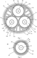
- Fig. 1 shows a cross-sectional view of an example of a three-core submarine power cable 1.
- the three-core submarine power cable 1 is an HV or an EHV three-core submarine power cable.
- the three-core submarine power cable 1 is an AC power cable.
- the HV or EHV three-core submarine power cable 1 comprises three power cores 3a-3c.
- the power cores 3a-3c are stranded.
- Each power core 3a-3c comprises a respective conductor 5a-5c.
- Each power core 3a-3c comprises an insulation system 7a-7c arranged around the respective conductor 5a-5c.
- Each insulation system 7a-7c comprises an inner semiconducting layer 9a-9c arranged around the conductor 5a-5c, an insulation layer 11a-11c arranged around the inner semiconducting layer 9a-9c, and an outer semiconducting layer 13a-13c arranged around the insulation layer 11a-11c.
- the insulation layer 11a-11c comprises a first polymeric material.
- the first polymeric material may for example comprise a polyolefin such as a crosslinked polyolefin, e.g., crosslinked polyethylene (XLPE), or a thermoplastic polyolefin such as polypropylene, or a polyolefin elastomer such as ethylene propylene rubber (EPR), or ethylene propylene diene monomer (EPDM) rubber.
- XLPE crosslinked polyethylene
- EPR ethylene propylene rubber
- EPDM ethylene propylene diene monomer
- the inner semiconducting layer 9a-9c and the outer semiconducting layer 13a-13c may comprise polymeric material mixed with conductive particles such as carbon black.
- the insulation system 7a-7c may be an extruded insulation system, for example a triple extruded insulation system.
- Each power core 3a-3c may further comprise a respective metallic water blocking layer 15a-15c arranged around the insulation system 7a-7c.
- the metallic water blocking layer 15a-15c may for example comprise stainless steel, copper, aluminium, or lead.
- Each power core 3a-3c may comprise a respective polymeric sheath 17a-17c arranged around the insulation system 7a-7c. If the power cores 3a-3c comprise the metallic water blocking layer 15a-15c, the polymeric sheath 17a-17c is arranged around the metallic water blocking layer 15a-15c.
- the three-core submarine power cable 1 may comprise an armour layer 19 comprising a plurality of armour wires 21 arranged helically around the three stranded power cores 3a-3c.
- the three-core submarine power cable 1 comprises an outer layer 23, which forms the outermost layer of the three-core submarine power cable 1.
- the outer layer 23 may be an outer sheath comprising a polymeric material or an outer serving composed of helically wound polymeric yarns.
- Fig. 2 shows a cross-sectional view of a single core submarine power cable 25.
- the single core submarine power cable 25 is an HV or an EHV single core submarine power cable.
- the single core submarine power cable 25 is an AC power cable.
- the single core submarine power cable 25 may be designed to have the same power capacity as that of any one of the individual power cores 3a-3c.
- Three single core submarine power cables 25 together with the three-core submarine power cable 1 form part of an HV or EHV submarine power cable system, as will be described in more detail with reference to Fig. 3 .
- Each single core submarine power cable 25 is jointed with a respective one of the power cores 3a-3c.
- Each single core submarine power cable 25 comprises a conductor 27 and an insulation system 29 arranged around the conductor 27.
- the conductor 27 may for example be a round stranded conductor, a solid conductor, a keystone, or profile, conductor, or a Milliken conductor.
- the insulation system 29 comprises an inner semiconducting layer 31 arranged around the conductor 27, an insulation layer 33 arranged around the inner semiconducting layer 31, and an outer semiconducting layer 35 arranged around the insulation layer 33.
- the insulation layer 29 comprises the first polymeric material, i.e., the same polymeric material as the insulation layer 7a-7c of the power cores 3a-3c.
- the inner semiconducting layer 31 and the outer semiconducting layer 35 may comprise polymeric material mixed with conductive particles such as carbon black.
- the insulation system 29 may be an extruded insulation system, for example a triple extruded insulation system.
- Each single core submarine power cable 25 may comprise a respective metallic water blocking layer 37 arranged around the insulation system 29.
- the metallic water blocking layer 37 may for example comprise stainless steel, copper, aluminium, or lead.
- Each single core submarine power cable 25 may comprise a polymeric sheath 39 arranged around the insulation system 29.
- the single core submarine power cable 25 comprises the metallic water blocking layer 37
- the polymeric sheath 39 is arranged around the metallic water blocking layer 37.
- Each single core submarine power cable 25 may comprise a respective armour layer 41 comprising a plurality of armour wires 43 arranged helically around the insulation system 29 and, if present, the metallic water blocking layer 37.
- the armour wires 43 may for example comprise copper, aluminium, stainless steel, and/or a polymeric material.
- Each single core submarine power cable 25 comprises an outer layer 45 which forms the outermost layer of the single core submarine power cable 25.
- the outer layer 45 may be an outer sheath comprising a polymeric material or an outer serving composed of helically wound polymeric yarns.
- Fig. 3 schematically shows an example of an HV or EHV submarine power cable system 47 comprising a three-core submarine power cable such as the three-core submarine power cable 1, and three single core submarine power cables such as the single core submarine power cables 25.
- the HV or EHV submarine power cable system 47 also comprises a rigid joint 49 connecting the power cores 3a-3c of the three-core submarine power cable 1 with a respective one of the singe core submarine power cables 25.
- the rigid joint 49 may comprise three pre-moulded joint sleeves, each being arranged over a respective conductor joint, i.e., the joint between a conductor 5a-5c of the three-core submarine power cable 1 and a conductor 27 of one of the single core submarine power cables 25.
- the pre-moulded joint sleeves restore the insulation system over the conductor joint and may have field grading properties.
- the rigid joint 49 may comprise three inner casings.
- the inner casings may be made of metal.
- Each conductor joint and pre-moulded sleeve is arranged in a respective inner casing, to which the metallic water blocking layers 15a-15c and 37 may be thermally attached, e.g., by soldering or welding, along their entire circumference.
- the rigid joint 49 further comprises an outer casing 51, inside which the three inner casing are arranged.
- the outer casing 51 may be made of metal such as stainless steel or aluminium.
- the armour wires 21 of the three-core submarine power cable 1 may be attached to the outer casing 51.
- the armour wires 43 of the three single core submarine power cables 25 may be attached to the outer casing 51.
- the attachment of the armour wires 21 and 43 may for example be by means of welding to a respective weld sleeve of the outer casing 51, and/or by clamping.
- the single core submarine power cables 25 are arranged spaced apart from each other with at least a distance d, which may be at least 1 m.
- each single core submarine power cables 25 may be arranged at a distance of at least 1 m from any of the other two single core submarine power cables 25.
- the distance d is typically not achieved at the rigid joint 49, where the three single core submarine power cables 25 exit the outer casing 51 but some distance, such as one or more metres, away from the outer casing 51 as at least two of the single core submarine power cables 25 are bent away from each of the other single core submarine power cables 25.
- Fig. 4 shows an example of a submarine power cable installation 53, comprising the HV or EHV submarine power cable system 47 in an installed state.
- the HV or EHV submarine power cable system 47 is shown in the context of an offshore wind farm including offshore wind turbines, such as wind turbine 55, and an offshore substation 57 connected to the wind turbine 55, arranged in water 54.
- An array cable 59 is connected between the wind turbines 55 and the offshore substation 57.
- the three-core submarine power cable 1, which may be an export cable, is connected to the offshore substation 57 and is lead towards shore.
- the three-core submarine power cable 1 is thus arranged offshore, under water.
- the rigid joint 49 is installed offshore before landfall of the three single core submarine power cables 25. Landfall begins in level with the seashore and is located to the right of the vertical dashed line 61, as illustrated by the right-pointing arrow.
- a first section 63 of each three single core submarine power cable 25 extends under water. Typically, the first section 63 extends underground offshore.
- a second section 65 of each of the three single core submarine power cables 25 extends on land. Typically, the second section 65 is located onshore underground.
- the three single core submarine power cables 25 are located deeper than the rigid joint 49.
- a method of operating the submarine power cable installation 53 comprises increasing the current rating of the HV or EHV submarine power cable system 47 based on reduced heat losses in the three single core submarine power cables 25 as compared to if the three single core submarine power cables 25 would be replaced with a three-core submarine power cable along the first section 63 and the second section 65, e.g. if no jointing of the three-core submarine power cable 1 would have been made by means of the rigid joint 49.
Landscapes
- Physics & Mathematics (AREA)
- Spectroscopy & Molecular Physics (AREA)
- Insulated Conductors (AREA)
- Laying Of Electric Cables Or Lines Outside (AREA)
- Cable Accessories (AREA)
Priority Applications (5)
| Application Number | Priority Date | Filing Date | Title |
|---|---|---|---|
| EP23153891.9A EP4407637A1 (fr) | 2023-01-30 | 2023-01-30 | Système de câble d'alimentation sous-marin hv à trois noyaux ou à trois noyaux |
| CA3225179A CA3225179A1 (fr) | 2023-01-30 | 2023-12-29 | Systeme de cable d'alimentation de sous-marin haute tension ou tres haute tension a trois ames ou a trois ames individuelles |
| KR1020240004752A KR20240119833A (ko) | 2023-01-30 | 2024-01-11 | 3-코어 내지 3 개의 단일 코어 hv 또는 ehv 해저 전력 케이블 시스템 |
| JP2024005828A JP2024108134A (ja) | 2023-01-30 | 2024-01-18 | 3芯から3つの単芯へのhvまたはehv海底電力ケーブルシステム |
| US18/421,501 US20240258784A1 (en) | 2023-01-30 | 2024-01-24 | Three-Core to Three Single Core HV or EHV Submarine Power Cable System |
Applications Claiming Priority (1)
| Application Number | Priority Date | Filing Date | Title |
|---|---|---|---|
| EP23153891.9A EP4407637A1 (fr) | 2023-01-30 | 2023-01-30 | Système de câble d'alimentation sous-marin hv à trois noyaux ou à trois noyaux |
Publications (1)
| Publication Number | Publication Date |
|---|---|
| EP4407637A1 true EP4407637A1 (fr) | 2024-07-31 |
Family
ID=85150359
Family Applications (1)
| Application Number | Title | Priority Date | Filing Date |
|---|---|---|---|
| EP23153891.9A Pending EP4407637A1 (fr) | 2023-01-30 | 2023-01-30 | Système de câble d'alimentation sous-marin hv à trois noyaux ou à trois noyaux |
Country Status (5)
| Country | Link |
|---|---|
| US (1) | US20240258784A1 (fr) |
| EP (1) | EP4407637A1 (fr) |
| JP (1) | JP2024108134A (fr) |
| KR (1) | KR20240119833A (fr) |
| CA (1) | CA3225179A1 (fr) |
Citations (2)
| Publication number | Priority date | Publication date | Assignee | Title |
|---|---|---|---|---|
| US20160155537A1 (en) * | 2013-09-24 | 2016-06-02 | Furukawa Electric Co., Ltd. | Submarine cable and multilayer tape for impermeable layer of same |
| EP3839981A1 (fr) * | 2019-12-19 | 2021-06-23 | NKT HV Cables AB | Câble électrique sous-marin ca avec réduction des pertes |
Family Cites Families (7)
| Publication number | Priority date | Publication date | Assignee | Title |
|---|---|---|---|---|
| US3816639A (en) * | 1973-05-14 | 1974-06-11 | Gen Electric | High voltage cable splice with graded insulation and method of making same |
| IT1175762B (it) * | 1984-09-28 | 1987-07-15 | Pirelli Cavi Spa | Giunto per cavi ad isolante estruso |
| US5667008A (en) * | 1991-02-06 | 1997-09-16 | Quick Connectors, Inc. | Seal electrical conductor arrangement for use with a well bore in hazardous areas |
| FR3006099B1 (fr) * | 2013-05-22 | 2015-05-08 | Nexans | Cable electrique comprenant au moins une couche electriquement isolante |
| US11881692B2 (en) * | 2019-02-20 | 2024-01-23 | Ls Cable & System Ltd. | Intermediate connection structure of power cable |
| KR20230134862A (ko) * | 2022-03-15 | 2023-09-22 | 엘에스전선 주식회사 | 손실 저감 케이블 |
| TWI853667B (zh) * | 2022-11-25 | 2024-08-21 | 南韓商Ls電線有限公司 | 具有改善的水樹性質的用於離岸風力發電的海底電纜 |
-
2023
- 2023-01-30 EP EP23153891.9A patent/EP4407637A1/fr active Pending
- 2023-12-29 CA CA3225179A patent/CA3225179A1/fr active Pending
-
2024
- 2024-01-11 KR KR1020240004752A patent/KR20240119833A/ko active Pending
- 2024-01-18 JP JP2024005828A patent/JP2024108134A/ja active Pending
- 2024-01-24 US US18/421,501 patent/US20240258784A1/en active Pending
Patent Citations (2)
| Publication number | Priority date | Publication date | Assignee | Title |
|---|---|---|---|---|
| US20160155537A1 (en) * | 2013-09-24 | 2016-06-02 | Furukawa Electric Co., Ltd. | Submarine cable and multilayer tape for impermeable layer of same |
| EP3839981A1 (fr) * | 2019-12-19 | 2021-06-23 | NKT HV Cables AB | Câble électrique sous-marin ca avec réduction des pertes |
Non-Patent Citations (1)
| Title |
|---|
| PRYSMIAN GROUP: "Transition Joints", 25 October 2017 (2017-10-25), pages 1 - 8, XP093054583, Retrieved from the Internet <URL:https://dk.prysmiangroup.com/sites/default/files/atoms/files/TRANSITION-JOINTS.pdf> [retrieved on 20230615] * |
Also Published As
| Publication number | Publication date |
|---|---|
| US20240258784A1 (en) | 2024-08-01 |
| CA3225179A1 (fr) | 2025-04-09 |
| KR20240119833A (ko) | 2024-08-06 |
| JP2024108134A (ja) | 2024-08-09 |
Similar Documents
| Publication | Publication Date | Title |
|---|---|---|
| US10373735B2 (en) | Submarine electrical cable and submarine cable operation method | |
| EP3839981A1 (fr) | Câble électrique sous-marin ca avec réduction des pertes | |
| EP3488448B1 (fr) | Câble sous-marin isolé | |
| US20200135361A1 (en) | Reinforced Submarine Power Cable | |
| EP3333995B1 (fr) | Système de câble sous-marin à faible perte et procédé de pose d'un système de point d'arrivée de câbles sous-marins | |
| KR20240081434A (ko) | 해저케이블 | |
| EP3605559B1 (fr) | Câble triphasé haute tension | |
| EP4407637A1 (fr) | Système de câble d'alimentation sous-marin hv à trois noyaux ou à trois noyaux | |
| US20250336567A1 (en) | Submarine cable | |
| EP4220668B1 (fr) | Câble haute tension ca | |
| US20240282479A1 (en) | Submarine power cable with fluid transport capability | |
| US20250087385A1 (en) | Submarine Power Cable System With Reduced Losses | |
| US20240312670A1 (en) | Submarine Power Cable Having Sections With Different Water Permeability | |
| EP4614529A1 (fr) | Câble d'alimentation en courant continu sous-marin | |
| SE2151093A1 (en) | Armoured direct current submarine power cable | |
| HK40003100B (en) | Insulated submarine cable | |
| HK40003100A (en) | Insulated submarine cable |
Legal Events
| Date | Code | Title | Description |
|---|---|---|---|
| PUAI | Public reference made under article 153(3) epc to a published international application that has entered the european phase |
Free format text: ORIGINAL CODE: 0009012 |
|
| STAA | Information on the status of an ep patent application or granted ep patent |
Free format text: STATUS: THE APPLICATION HAS BEEN PUBLISHED |
|
| AK | Designated contracting states |
Kind code of ref document: A1 Designated state(s): AL AT BE BG CH CY CZ DE DK EE ES FI FR GB GR HR HU IE IS IT LI LT LU LV MC ME MK MT NL NO PL PT RO RS SE SI SK SM TR |
|
| STAA | Information on the status of an ep patent application or granted ep patent |
Free format text: STATUS: REQUEST FOR EXAMINATION WAS MADE |
|
| 17P | Request for examination filed |
Effective date: 20250130 |