EP4410087A1 - Moissonneuse agricole automotrice - Google Patents
Moissonneuse agricole automotrice Download PDFInfo
- Publication number
- EP4410087A1 EP4410087A1 EP23212711.8A EP23212711A EP4410087A1 EP 4410087 A1 EP4410087 A1 EP 4410087A1 EP 23212711 A EP23212711 A EP 23212711A EP 4410087 A1 EP4410087 A1 EP 4410087A1
- Authority
- EP
- European Patent Office
- Prior art keywords
- crop
- harvesting machine
- swath
- gap
- acceleration
- Prior art date
- Legal status (The legal status is an assumption and is not a legal conclusion. Google has not performed a legal analysis and makes no representation as to the accuracy of the status listed.)
- Granted
Links
Images


Classifications
-
- A—HUMAN NECESSITIES
- A01—AGRICULTURE; FORESTRY; ANIMAL HUSBANDRY; HUNTING; TRAPPING; FISHING
- A01D—HARVESTING; MOWING
- A01D43/00—Mowers combined with apparatus performing additional operations while mowing
- A01D43/06—Mowers combined with apparatus performing additional operations while mowing with means for collecting, gathering or loading mown material
- A01D43/07—Mowers combined with apparatus performing additional operations while mowing with means for collecting, gathering or loading mown material in or into a trailer
- A01D43/073—Mowers combined with apparatus performing additional operations while mowing with means for collecting, gathering or loading mown material in or into a trailer with controllable discharge spout
-
- A—HUMAN NECESSITIES
- A01—AGRICULTURE; FORESTRY; ANIMAL HUSBANDRY; HUNTING; TRAPPING; FISHING
- A01D—HARVESTING; MOWING
- A01D43/00—Mowers combined with apparatus performing additional operations while mowing
- A01D43/08—Mowers combined with apparatus performing additional operations while mowing with means for cutting up the mown crop, e.g. forage harvesters
- A01D43/085—Control or measuring arrangements specially adapted therefor
-
- A—HUMAN NECESSITIES
- A01—AGRICULTURE; FORESTRY; ANIMAL HUSBANDRY; HUNTING; TRAPPING; FISHING
- A01D—HARVESTING; MOWING
- A01D43/00—Mowers combined with apparatus performing additional operations while mowing
- A01D43/08—Mowers combined with apparatus performing additional operations while mowing with means for cutting up the mown crop, e.g. forage harvesters
- A01D43/086—Mowers combined with apparatus performing additional operations while mowing with means for cutting up the mown crop, e.g. forage harvesters and means for collecting, gathering or loading mown material
- A01D43/087—Mowers combined with apparatus performing additional operations while mowing with means for cutting up the mown crop, e.g. forage harvesters and means for collecting, gathering or loading mown material with controllable discharge spout
Definitions
- the present invention relates to a self-propelled agricultural harvesting machine according to the preamble of claim 1. Furthermore, the present invention relates to a method for operating a self-propelled agricultural harvesting machine according to the preamble of claim 14.
- a self-propelled agricultural harvesting machine of the type mentioned above is known from EP 1 380 204 A1 known. It describes an agricultural harvesting machine designed as a forage harvester, with at least one post-acceleration device for variable acceleration of the crop and with a transfer device arranged downstream of the post-acceleration device for ejecting the crop into a loading container.
- the width of a crop passage gap of the post-acceleration device which is formed between the post-acceleration device and a wall of a conveyor channel opposite it, can be adjusted by means of a gap changing device. This influences the intensity of the intervention of the post-acceleration device on the crop.
- the gap changing device is assigned a control device which controls the gap changing device by means of a generated control signal.
- a control device which controls the gap changing device by means of a generated control signal.
- it is known from the EP 1 380 204 A1 It is known to adjust the width of the crop passage gap depending on the crop throughput, which is determined by sensors that measure the moisture, density and speed of the crop. The sensors are arranged inside the harvester along the crop conveying path between the intake element and the transfer device. The reaction to changes in the crop flow is therefore always delayed.
- the increasing driving speed which is accompanied by an increase in area performance, leads to a further reduction in the reaction time to changing harvesting conditions or harvesting situations during the harvesting process.
- the EN 10 2020 002 864 A1 describes an agricultural harvesting machine designed as a forage harvester, with at least one post-acceleration device for accelerating of crops and with a transfer device downstream of the post-acceleration device for ejecting the crops into a loading container.
- the post-acceleration device is used to accelerate the crops by being in an acceleration position in which the post-acceleration device protrudes into the conveyor channel.
- the post-acceleration device is in a passive position in which the post-acceleration device is extended out of the conveyor channel and acts as a fan. In the passive position, the post-acceleration device interacts slightly mechanically with the crops. Switching between the acceleration position and the passive position also depends on the presence of a conditioning device for processing corn kernels.
- a self-propelled agricultural harvesting machine in particular a forage harvester, is proposed with at least one post-acceleration device for variable acceleration of the crop and with a transfer device arranged downstream of the post-acceleration device for ejecting the crop into a loading container, wherein the width of a crop passage gap of the post-acceleration device can be adjusted by means of a gap changing device for variable acceleration of the crop, wherein a control device is assigned to the gap changing device which controls the gap changing device by means of a generated control signal.
- control device is set up to receive and evaluate data generated by a swath detection device arranged on the harvesting machine, which data comprise properties of the crop to be picked up by the harvesting machine in the form of a swath, and depending on the evaluation of the data from the swath detection device to generate the control signals for adjusting the width of the crop passage gap.
- the invention is based on the idea of detecting irregularities in the crop deposited in the form of a swath in the area in front of the harvesting machine at an early stage in order to be able to react to changing harvesting conditions or harvesting situations more quickly, i.e. more proactively.
- the swath is deposited in a preceding processing process in which irregularities can occur during depositing due to various influences. For example, fluctuations in crop density, damage to the implement used for swath depositing and/or operating errors occurring during swath depositing lead to such irregularities.
- the weather conditions both during and after swath depositing and during the collection of the swath by the harvesting machine set up for this purpose also have an influence.
- control according to the invention makes it possible to avoid or at least minimize the risk of blockages caused by uneven swaths or an uneven crop mass of the swaths to be collected. If unevenness in the swath is detected, the width of the crop passage gap can be changed in response at an early stage. This avoids disruptions in the crop flow and thus downtimes to clear blockages inside the harvesting machine.
- the width of the crop passage gap of the post-acceleration device refers to the distance between the post-acceleration device and an opposite wall of a conveyor channel of the harvesting machine.
- the control device can be part of a control and regulating unit of the harvesting machine, which takes on additional tasks, or can be designed as a separate control unit that is connected to a higher-level control and regulating unit of the harvesting machine.
- the swath detection device can be equipped with at least one optical sensor for detecting an apron area, wherein the sensor detects the presence and/or a shape of the swath in front of the harvesting machine and wherein the Swath detection device transmits this data to the control device.
- the at least one optical sensor can preferably be a camera, an RGB camera, a 3D camera and/or a LIDAR.
- the shape of the swath refers to the width, the height and the contour.
- the shape of the swath can provide information about the evenness of the distribution and/or the amount of crop to be picked up.
- the presence of the swath can be used to detect changes in the harvesting situation.
- a gap in the swath leads to a temporary decrease in the amount of crop to be overloaded, which can be responded to by changing the width of the crop passage gap.
- a change made only lasts for the period or distance until the end of the gap is reached.
- Another change in the harvesting situation is reaching the headland during which no crop is picked up.
- control device can be designed to determine the crop throughput based on the shape of the swath.
- an image processing system can be provided which interacts with the control device or is a component of the control device.
- the swath detection device can be equipped with at least one sensor arranged along the crop flow, which detects properties of the crop, whereby the swath detection device transmits this data to the control device.
- the at least one sensor set up to detect crop properties can be an NIR sensor and/or a moisture sensor.
- the arrangement along the crop flow can take place at any point within the harvesting machine.
- a preferred arrangement of the at least one sensor can be provided on the transfer device. While the moisture sensor only detects the moisture of the crop, an NIR sensor detects additional information on properties of the crop.
- the swath detection device can be designed with at least one sensor arrangement which is set up to detect a layer height in the intake element, wherein the swath detection device transmits the data on the layer height determined by the at least one sensor arrangement to the control device for determining a crop throughput.
- the at least one sensor arrangement can be set up to detect forces that are applied to the harvested crop by at least one pair of rollers of a feeder element upstream of the post-acceleration element.
- the at least one sensor arrangement can be set up to detect a deflection of a pair of rollers or the pairs of rollers of the feeder element.
- the at least one sensor arrangement, which is additionally set up to determine the crop throughput can improve the accuracy of the determination of the crop throughput, thereby enabling more precise control for adjusting the width of the crop passage gap by the control device.
- control device can have a memory unit in which a relative or absolute threshold value for a change in the crop throughput is stored, the exceedance of which is interpreted by the control device as an indicator for adjusting the width of the crop passage gap.
- a threshold value can be provided in order to avoid over-regulation of the gap changing device due to only minor deviations in the shape of the swath, which can have an undesirable effect on the crop flow and the transfer process.
- the post-acceleration element can have an axis which is mounted at the end in guides which are arranged on side walls which delimit a housing which at least partially encloses the post-acceleration element, wherein the gap-changing device for the, in particular translational, movement of the post-acceleration element comprises an actuator by means of which the width of the crop passage gap can be changed.
- a pivoting movement of the post-acceleration element is also conceivable in order to change the width of the crop passage gap.
- the actuators can comprise mechanically, hydraulically and/or electromechanically actuated drive elements.
- At least one hydraulically and/or electromechanically actuated drive element can be provided, for example, at least one hydraulic cylinder or at least one linear motor.
- At least one lever arrangement and a shaft or a spindle can be provided, for example, as mechanically actuated drive elements.
- the at least one hydraulically and/or electromechanically actuated drive element can act on the shaft at a first articulation point. and pivot them about a fixed axis of rotation.
- the at least one lever arrangement can engage a second articulation point on the shaft that is spaced apart from the first articulation point, so that the movement of the hydraulically and/or electromechanically actuated drive element is transmitted to the lever arrangement.
- the first articulation point and the second articulation point can be arranged at opposite points on the shaft. Furthermore, two spindles connected via a connecting link can be used for adjustment.
- a sensor assigned to the post-acceleration device and/or the actuator transmits the respective setting value to the control device.
- the gap change device can have an adjustment characteristic with an essentially progressively increasing course of the adjustment of the width of the crop passage gap.
- the advantage of such a gap change device is that when setting small distance values for the width of the crop gap, a very precise adjustment is made possible by the gap change device, while when setting increasing distance values for the width, the change is achieved more quickly by controlling the gap change device.
- the former is relevant for dry crops and/or low crop throughputs, which can be due, for example, to an irregularity in the shape of the swath, a gap in the swath or cutting or reaching a headland.
- the latter is relevant for essentially uniform larger crop throughputs in order to optimize the power consumption of the post-acceleration device.
- the gap changing device can be designed to set the width of the crop passage gap to a minimum value of 2 mm up to a maximum value of 80 mm.
- the minimum value for the width of the crop passage gap leads to a maximum acceleration of the crop at a given drive speed of the post-acceleration device.
- the gap changing device can be designed to adjust the width of the crop passage gap continuously.
- At least one characteristic curve or a characteristic curve field for the width of the crop passage gap to be set can be stored in the storage unit depending on of at least one property of the crop and/or the crop throughput, wherein the control device comprises a computing unit which evaluates the at least one characteristic curve or the at least one characteristic curve field for controlling the gap changing device.
- the control device comprises a computing unit which evaluates the at least one characteristic curve or the at least one characteristic curve field for controlling the gap changing device.
- the data provided by the swath detection device form input variables and the gap width to be set forms the output variable.
- Data from the at least one sensor which is set up to detect properties of the crop and/or the at least one sensor arrangement by means of which the crop throughput can be determined can form additional input variables.
- control device can be designed to control the gap changing device in such a way as to reduce the width of the crop passage gap as the crop becomes increasingly dry and/or the crop throughput decreases.
- Increasing dryness and/or a decrease in the crop throughput require a reduction in the width of the crop passage gap in order to ensure safe loading into the loading container.
- control device can be set up to automatically control the gap change device. This can reduce the workload on the operator of the harvesting machine.
- automation enables the width of the crop passage gap to be controlled and adjusted more quickly and precisely in order to make the operation of the post-acceleration device more efficient.
- the object according to the invention is further achieved by a method for operating a self-propelled agricultural harvesting machine, in particular a forage harvester, with at least one post-acceleration element for variable acceleration of crops and with a transfer device arranged downstream of the post-acceleration element for ejecting the crops into a loading container, wherein for variable acceleration of the crops the width of a crop passage gap of the post-acceleration element is adjusted by means of a gap changing device, wherein the gap changing device is controlled by control signals generated by a control device, according to independent claim 14.
- the control device receives data generated by a swath detection device and evaluates which properties of the of the crop to be picked up by the harvesting machine in the form of a swath, and that the control device generates the control signals for adjusting the width of the crop passage gap depending on the evaluation of the data provided by the swath detection device.
- the method is characterized in that the post-acceleration device is operated more efficiently. The risk of blockages occurring in the conveyor channel can be avoided or at least reduced. This goes hand in hand with the avoidance of downtimes that have to be spent on removing such blockages. Reference may be made to the advantages of the agricultural harvesting machine according to the invention.
- the rapid setting of large distance values for the width of the crop passage gap 14 is relevant in order to be able to react to a sudden increase in crop throughput, as occurs shortly after driving into the crop, and to optimize energy consumption.
- a self-propelled agricultural harvesting machine 1 designed as a field chopper is shown, on which an attachment 2 is arranged in the front area for picking up crops deposited on the ground.
- the attachment 2 varies depending on the type of crop to be harvested or picked up.
- the attachment 2 picks up the crop from the field and conveys it to an intake element 3, which in the embodiment shown consists of a roller group with upper and lower intake rollers 4, 5.
- the intake rollers 4, 5 of the intake element 3 exert a pressing force on the picked up crop.
- the intake element 3 conveys the crop, which has been compacted into a crop mat, to a chopping device 6, which has a rotating chopping drum 7 with chopping knives 8 arranged around its circumference.
- the chopping knives 8 cut the crop mat fed by the intake element 3 at a counter-blade 9.
- the cut or chopped crop is fed by the rotational movement of the chopping drum 7 into a downstream conveyor channel 10, from where it is processed by an optional post-processing device 11, also referred to as a conditioning device or corn cracker, which is arranged in the crop flow path, depending on the equipment of the forage harvester 1, and is conveyed by a downstream, rotatingly driven post-acceleration element 12, additionally accelerated by an adjustable transfer device 13 into a transport vehicle.
- the optional post-processing device 11 can either be swung out of the crop flow path or completely removed.
- the transfer device 13 can be rotated about a vertical axis, for example by means of a slewing ring.
- the transfer device 13 can be swiveled about a horizontal axis.
- a so-called ejection flap can be arranged, which can be pivoted relative to the transfer device 13 about a horizontally extending axis.
- a drive motor 19 is provided to drive the working units of the harvesting machine 1, ie the attachment 2, intake device 3, chopping device 6, optionally the post-processing device 11, and the post-acceleration device 12.
- the working units can be driven by a main drive train (not shown) with the engine output shaft of the drive motor 19.
- the drive motor 19 also serves to operate a hydrodynamic drive of the forage harvester 1.
- the harvesting machine 1 comprises a driver's cab 17 in which an input-output unit 18 is arranged.
- the harvesting machine 1 also comprises a control device 14 which comprises a storage unit 15 for storing data and a computing unit 16 for processing the data stored in the storage unit 15.
- the control device 14 is designed to support an operator of the harvesting machine 1 in operating the same.
- the control device 14 is designed to control at least the post-acceleration element 12.
- a swath detection device 20 is arranged on the harvesting machine 1.
- the swath detection device 20 is equipped with at least one optical sensor 21 for detecting an apron area, i.e. a section located in front of the harvesting machine 1 in the direction of travel.
- the at least one optical sensor 21 is designed to detect the presence and/or shape of a swath 23 in front of the harvesting machine 1.
- the swath detection device 20 transmits certain data to the control device 14 for evaluation via the at least one optical sensor 21.
- the at least one optical sensor 21 is connected to the control device 14 by means of a bus system 22 of the harvesting machine 1.
- the at least one optical sensor 21 can be designed as a camera, RGB camera, 3D camera or LIDAR.
- FIG.1 shows an exemplary arrangement of the at least one optical sensor 21 directly on the attachment 2.
- Fig.2 an advantageous arrangement on the driver's cab 17 is shown.
- the swath detection device 20 can be equipped with at least one sensor 24 arranged along the crop flow, which detects properties of the collected crop.
- the swath detection device 20 also transmits this data to the control device 14 for evaluation.
- the at least one sensor 24 arranged along the crop flow can preferably be an NIR sensor and/or a moisture sensor.
- the arrangement of the at least one sensor 24 along the crop flow can take place at any point within the harvesting machine 1.
- a preferred arrangement of the at least A sensor 24 can be provided on the transfer device 13. While a moisture sensor only detects the moisture of the crop, an NIR sensor detects additional information about the properties of the crop.
- the swath detection device 20 can be designed with at least one sensor arrangement 25, which is set up to detect a layer height in the intake element 3. The presence of crop material and the throughput of collected crop material can be determined by means of the sensor arrangement 25.
- Fig. 2 is a schematic representation of the harvesting machine 1 according to Fig.1 with an attachment 2 designed as a pick-up for picking up the swath 23.
- the at least one sensor 21 arranged on the driver's cabin 17 detects the presence of the swath 23 as well as its geometry or shape with which the swath 23 was deposited on the ground in a previous process by means of scanning beams 26.
- the swath 23 generally has an irregular height contour H.
- the height contour H changes along the swath 23 depending, among other things, on the density of the previously harvested crop. Further influences can result from the preceding process of forming the swath 23.
- FIG.3 shows a schematic view of a harvesting situation of the harvester according to Fig. 2 from above.
- the harvesting machine 1 is accompanied by a towing vehicle 29 and a loading container 30 attached to it, which, for the purpose of unloading, travel in a lane substantially parallel to the harvesting machine 1 or in the lane behind the harvesting machine 1, depending on the harvesting situation.
- the swath 23 not only has an irregular height contour H, but also varies to different degrees in its width 27. 28 designates a section along the swath 23 to be collected, which, due to a lower crop density, has a smaller width 27' than the preceding section or a subsequent section.
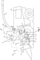
- Fig.4 is a schematic and exemplary side view of the post-acceleration device 12 of the harvesting machine 1 in a position with a minimum width of a crop passage gap 31.
- the minimum adjustable width of the adjustable crop passage gap 31 is approximately 2 mm.
- FIG.5 shows schematically and exemplarily a side view of the post-acceleration device 12 according to Fig.4 in a position with maximum width of the crop passage gap 31.
- the maximum adjustable width of the adjustable crop passage gap 31 is approximately 80 mm.
- the width of the adjustable crop passage gap 31 of the rotatingly driven post-acceleration device 12 designates the distance between the post-acceleration device 12 or its envelope circle and an opposite wall 32 of the conveyor channel 10 of the harvesting machine 1
- the post-acceleration device 12 has a rotation axis 33 which is movably mounted at the end in guides 34, as shown by the arrow VR.
- the guides 33 are arranged on side walls which delimit a housing 35 which at least partially encloses the post-acceleration device 12.
- the side walls can be part of the housing 35.
- the width of the crop passage gap 31 of the post-acceleration element 12 can be adjusted by means of a gap changing device 37.
- the gap changing device 37 is assigned to the control device 14, which is set up to control the gap changing device 37 by control signals generated by the control device 14.
- the gap changing device 37 comprises an actuator for the, in particular translational, movement (arrow VR) of the post-acceleration element 12, by means of which the width of the crop passage gap 31 can be changed.
- the system reacts to different operating situations in which a different acceleration of the crop by the post-acceleration element 12 is required.
- the actuators of the gap changing device 37 comprise mechanically, hydraulically and/or electromechanically actuated drive elements 38, 39, 40.
- the gap changing device 37 comprises at least one hydraulic cylinder 38, a shaft 39 and at least one lever arrangement 40 as drive elements.
- a spindle can be provided instead of the shaft 39. It is also conceivable that two spindles connected via a connecting link are used for adjustment.
- the at least one hydraulically and/or electromechanically actuated drive element here and preferably the at least one hydraulic cylinder 38, can engage at a first articulation point 41 on the shaft 39 and pivot the shaft about a fixed axis of rotation 42.
- the lever arrangement 40 engages at a second articulation point 43 on the shaft 39, which is spaced apart from the first articulation point 41, so that the movement of the at least one hydraulic cylinder 38 is transmitted to the at least one lever arrangement 40.
- the first articulation point 41 and the second articulation point 43 can be arranged at opposite points on the shaft 39.
- two hydraulically and/or electromechanically actuated drive elements here and preferably two hydraulic cylinders 38, which are arranged spaced apart from one another are provided, which engage the shaft 39 in end regions.
- the provision of two hydraulically and/or electromechanically actuated drive elements enables a more uniform adjustment of the shaft 39.
- the retraction of the piston rod of at least one hydraulic cylinder 38 causes the shaft 39 to rotate or pivot anti-clockwise, whereby the axis of rotation 33 of the post-acceleration element 12 is moved in the direction of the wall 32 of the conveyor channel 10 until the minimum adjustable width of the crop passage gap 31 is reached, as shown in Fig.4 shown.
- the extension of the piston rod of the hydraulic cylinder 38 causes the shaft 39 to rotate or pivot clockwise, whereby the axis of rotation 33 of the post-acceleration device 12 is increasingly spaced from the wall 32 until the maximum adjustable width of the crop passage gap 31 is reached, as shown in Fig.5 shown.
- the gap changing device 37 has an adjustment characteristic with a substantially progressively increasing course of the adjustment of the width of the crop passage gap 31.
- the advantage of a gap changing device designed in this way 37 is that when setting small distance values, in particular less than or equal to 30 mm, a very precise adjustment is made possible by the gap changing device 37 for the width of the crop gap 31, while when setting increasing distance values, in particular greater than 30 mm, the change in width is achieved more quickly by controlling the gap changing device 37.
- a precise adjustment of small distance values for the width of the crop passage gap 31 is relevant for dry crops and/or for low crop throughputs.
- the precise setting of small distance values for the width of the crop passage gap 31 enables optimal acceleration and more energy-efficient operation of the post-acceleration device 12 when the crop is dry and/or the crop throughput is low.
- the particularly rapid setting of large distance values for the width of the crop passage gap 31 is relevant in order to be able to react to a sudden increase in crop throughput, as occurs shortly after driving into the crop, and to optimize energy consumption.
- At least one characteristic curve 44 or a characteristic curve field for the width of the crop passage gap 31 to be set as a function of at least one property of the crop and the crop throughput can be stored in the memory unit 15.
- the computing unit 16 of the control device 14 can evaluate the at least one characteristic curve 44 or the at least one characteristic curve field for controlling the gap changing device 37.
- a relative or absolute threshold value for a change in the crop throughput can be stored in the memory unit 15, the exceedance of which is interpreted by the control device 14 as an indicator for adjusting the width of the crop passage gap 31.
- a threshold value can be provided in order to avoid over-regulation of the gap changing device 37. This can prevent the gap changing device 37 from being activated in order to react to this change due to only minor deviations in the shape of the swath and an associated change in the crop throughput.
- the control device 14 is designed to control the gap changing device 37 in such a way as to reduce the width of the crop passage gap 31 as the crop becomes increasingly dry and/or the crop throughput decreases. Increasing dryness and/or a decrease in the crop throughput require a reduction in the width of the crop passage gap 31 to ensure safe loading into the loading container 30.
- the control device 14 is preferably set up for automatically controlling the gap changing device 37.
- the gap changing device 37 can be automatically controlled in order to operate the post-acceleration device 12 efficiently.
- the adjustment characteristic of the gap changing device 37 which has a substantially progressively increasing course, enables improved adaptation to different harvesting conditions and/or crop properties.
- a more sensitive and precise setting of small distance values for the width of the crop passage gap 31 with low crop throughput and/or dry crop is offset by an increasingly faster setting of distance values for the width of the crop passage gap 31 when the crop throughput increases disproportionately.
- a disproportionate increase occurs, for example, after cutting or re-entering the crop after driving through a headland.
Landscapes
- Life Sciences & Earth Sciences (AREA)
- Environmental Sciences (AREA)
- Guiding Agricultural Machines (AREA)
- Agricultural Machines (AREA)
- Harvesting Machines For Root Crops (AREA)
Applications Claiming Priority (4)
| Application Number | Priority Date | Filing Date | Title |
|---|---|---|---|
| DE102023102282.2A DE102023102282A1 (de) | 2023-01-31 | 2023-01-31 | Selbstfahrende landwirtschaftliche Erntemaschine |
| DE102023102284.9A DE102023102284A1 (de) | 2023-01-31 | 2023-01-31 | Selbstfahrende landwirtschaftliche Erntemaschine |
| DE102023102283.0A DE102023102283A1 (de) | 2023-01-31 | 2023-01-31 | Selbstfahrende landwirtschaftliche Erntemaschine |
| DE102023000284.4A DE102023000284A1 (de) | 2023-01-31 | 2023-01-31 | Selbstfahrender Feldhäcksler |
Publications (2)
| Publication Number | Publication Date |
|---|---|
| EP4410087A1 true EP4410087A1 (fr) | 2024-08-07 |
| EP4410087B1 EP4410087B1 (fr) | 2025-08-20 |
Family
ID=88978183
Family Applications (4)
| Application Number | Title | Priority Date | Filing Date |
|---|---|---|---|
| EP23212723.3A Pending EP4410088A1 (fr) | 2023-01-31 | 2023-11-28 | Moissonneuse agricole automotrice |
| EP23212711.8A Active EP4410087B1 (fr) | 2023-01-31 | 2023-11-28 | Moissonneuse agricole automotrice |
| EP23212734.0A Active EP4410090B1 (fr) | 2023-01-31 | 2023-11-28 | Réglage de jeu d'accélérateur par dispositif à genouillère |
| EP23212728.2A Pending EP4410089A1 (fr) | 2023-01-31 | 2023-11-28 | Moissonneuse agricole automotrice |
Family Applications Before (1)
| Application Number | Title | Priority Date | Filing Date |
|---|---|---|---|
| EP23212723.3A Pending EP4410088A1 (fr) | 2023-01-31 | 2023-11-28 | Moissonneuse agricole automotrice |
Family Applications After (2)
| Application Number | Title | Priority Date | Filing Date |
|---|---|---|---|
| EP23212734.0A Active EP4410090B1 (fr) | 2023-01-31 | 2023-11-28 | Réglage de jeu d'accélérateur par dispositif à genouillère |
| EP23212728.2A Pending EP4410089A1 (fr) | 2023-01-31 | 2023-11-28 | Moissonneuse agricole automotrice |
Country Status (2)
| Country | Link |
|---|---|
| US (1) | US20240251713A1 (fr) |
| EP (4) | EP4410088A1 (fr) |
Families Citing this family (1)
| Publication number | Priority date | Publication date | Assignee | Title |
|---|---|---|---|---|
| DE102023108278A1 (de) * | 2023-03-31 | 2024-10-02 | Deere & Company | Ballenpresse und Verfahren zum Betrieb einer Ballenpresse |
Citations (4)
| Publication number | Priority date | Publication date | Assignee | Title |
|---|---|---|---|---|
| EP1380204A1 (fr) | 2002-07-10 | 2004-01-14 | CLAAS Selbstfahrende Erntemaschinen GmbH | Méthode et dispositif pour le changement automatique de position de l'élément de post-accélération dans une moissonneuse agricole |
| EP1529428A1 (fr) * | 2003-11-06 | 2005-05-11 | Deere & Company | Procédé et système pour la direction automatique d'une machine agricole |
| DE102012223432B3 (de) * | 2012-12-17 | 2014-03-27 | Deere & Company | Anordnung zur Verstellung eines Auswurfbeschleunigerspalts zwischen dem von Paddeln eines Rotors einer Auswurfbeschleunigungseinrichtung eines Feldhäckslers beschriebenen Hüllkreis und einem konkaven Bereich eines den Rotor aufnehmenden Gehäuses |
| DE102020002864A1 (de) | 2020-05-13 | 2021-11-18 | Maschinenfabrik Bernard Krone GmbH & Co. KG | Feldhäcksler mit einem Förderkanal zum Fördern von Erntegut und Verfahren zum Fördern des Ernteguts |
Family Cites Families (12)
| Publication number | Priority date | Publication date | Assignee | Title |
|---|---|---|---|---|
| GB9926580D0 (en) * | 1999-11-11 | 2000-01-12 | Medicine | Crop processor and blower arrangement for a forage harvester |
| DE10018825A1 (de) * | 2000-04-15 | 2001-10-31 | Same Deutz Fahr Spa | Auswurfbeschleuniger für eine fahrbare Erntemaschine |
| DE102005038553A1 (de) * | 2005-08-12 | 2007-02-22 | Claas Selbstfahrende Erntemaschinen Gmbh | Verfahren zum Überladen von Erntegut |
| DE102007009587A1 (de) | 2007-02-26 | 2008-08-28 | Claas Selbstfahrende Erntemaschinen Gmbh | Vorrichtung zur Einstellung der Position des Nachbeschleunigungsorgans in einer landwirtschaftlichen Erntemaschine |
| UA111735C2 (uk) * | 2011-02-18 | 2016-06-10 | СіЕнЕйч ІНДАСТРІАЛ АМЕРІКА ЕлЕлСі | Система й спосіб керування траєкторією транспортного засобу, використовуваного зі збиральною машиною |
| DE102011052944A1 (de) * | 2011-08-24 | 2013-02-28 | Claas Selbstfahrende Erntemaschinen Gmbh | Landwirtschaftliche Erntemaschine |
| DE102011082052B4 (de) * | 2011-09-02 | 2015-05-28 | Deere & Company | Anordnung und Verfahren zur selbsttätigen Überladung von Erntegut von einer Erntemaschine auf ein Transportfahrzeug |
| DE102013209197A1 (de) * | 2013-05-17 | 2014-11-20 | Deere & Company | Erntemaschine mit vorausschauender Vortriebsgeschwindigkeitsregelung |
| DE102014106696A1 (de) * | 2014-05-13 | 2015-11-19 | Claas Selbstfahrende Erntemaschinen Gmbh | Feldhäcksler |
| DE102018104287A1 (de) * | 2018-02-26 | 2019-08-29 | Claas Selbstfahrende Erntemaschinen Gmbh | Feldhäcksler und Verfahren zum Betreiben eines Feldhäckslers |
| DE102020123526A1 (de) * | 2020-09-09 | 2022-03-10 | Claas Selbstfahrende Erntemaschinen Gmbh | Feldhäcksler |
| EP4023049B1 (fr) * | 2020-12-29 | 2025-02-19 | Agco Corporation | Système de commande de jeu de fonctionnement entre un ensemble concave et un rotor de traitement des cultures |
-
2023
- 2023-11-28 EP EP23212723.3A patent/EP4410088A1/fr active Pending
- 2023-11-28 EP EP23212711.8A patent/EP4410087B1/fr active Active
- 2023-11-28 EP EP23212734.0A patent/EP4410090B1/fr active Active
- 2023-11-28 EP EP23212728.2A patent/EP4410089A1/fr active Pending
-
2024
- 2024-01-31 US US18/428,061 patent/US20240251713A1/en active Pending
Patent Citations (4)
| Publication number | Priority date | Publication date | Assignee | Title |
|---|---|---|---|---|
| EP1380204A1 (fr) | 2002-07-10 | 2004-01-14 | CLAAS Selbstfahrende Erntemaschinen GmbH | Méthode et dispositif pour le changement automatique de position de l'élément de post-accélération dans une moissonneuse agricole |
| EP1529428A1 (fr) * | 2003-11-06 | 2005-05-11 | Deere & Company | Procédé et système pour la direction automatique d'une machine agricole |
| DE102012223432B3 (de) * | 2012-12-17 | 2014-03-27 | Deere & Company | Anordnung zur Verstellung eines Auswurfbeschleunigerspalts zwischen dem von Paddeln eines Rotors einer Auswurfbeschleunigungseinrichtung eines Feldhäckslers beschriebenen Hüllkreis und einem konkaven Bereich eines den Rotor aufnehmenden Gehäuses |
| DE102020002864A1 (de) | 2020-05-13 | 2021-11-18 | Maschinenfabrik Bernard Krone GmbH & Co. KG | Feldhäcksler mit einem Förderkanal zum Fördern von Erntegut und Verfahren zum Fördern des Ernteguts |
Also Published As
| Publication number | Publication date |
|---|---|
| EP4410087B1 (fr) | 2025-08-20 |
| US20240251713A1 (en) | 2024-08-01 |
| EP4410090B1 (fr) | 2025-10-29 |
| EP4410089A1 (fr) | 2024-08-07 |
| EP4410088A1 (fr) | 2024-08-07 |
| EP4410090A1 (fr) | 2024-08-07 |
Similar Documents
| Publication | Publication Date | Title |
|---|---|---|
| EP3662741B1 (fr) | Machine de travail agricole ainsi que procédé de fonctionnement d'une machine de travail agricole | |
| EP3533315B2 (fr) | Récolteuse-hacheuse-chargeuse de fourrage et procédé de fonctionnement d'une récolteuse-hacheuse-chargeuse de fourrage | |
| EP1051898B1 (fr) | Dispositif pour régler la vitesse d'avance d'une récolteuse utilisant la logique floue | |
| EP3494771B1 (fr) | Dispositif de hauteur de coupe automatique | |
| EP3593620A1 (fr) | Système de récolte | |
| EP1825740A1 (fr) | Procédé et dispositif destinés à la détermination des propriétés de compactage de biens de récolte | |
| EP3530101B1 (fr) | Récolteuse-hacheuse-chargeuse de fourrage automotrice | |
| EP1790210B1 (fr) | Dispositif d'alimentation pour une faucheuse-hâcheuse | |
| EP2248411A2 (fr) | Moissonneuse | |
| EP4154699B1 (fr) | Machine de travail agricole pourvu à commande de champ caractéristique | |
| DE102014102221B4 (de) | Verfahren und Steuerungssystem zum Betreiben eines Feldhäckslers sowie Feldhäcksler | |
| EP3607815A1 (fr) | Appareil de traitement agricole | |
| DE102011053163A1 (de) | System zur Steuerung einer Überladeeinrichtung | |
| EP4410087B1 (fr) | Moissonneuse agricole automotrice | |
| EP3552473B1 (fr) | Moissonneuse-batteuse avec contrôleur de rouleaux d'amenée | |
| EP3000301B1 (fr) | Moissonneuse-batteuse automotrice | |
| BE1026594B1 (de) | Anordnung zur Einstellung der Position der Gegenschneide eines Feldhäckslers | |
| EP4154697B1 (fr) | Système d'aide à la conduite d'un engin d'abattage-façonnage pourvu de mécanisme de coupe de bande | |
| DE102023102282A1 (de) | Selbstfahrende landwirtschaftliche Erntemaschine | |
| EP3967127B1 (fr) | Récolteuse-hacheuse-chargeuse de fourrage automotrice | |
| EP4154700A1 (fr) | Engin d'abattage-façonnage pourvu de mécanisme de coupe de bande | |
| DE102023102283A1 (de) | Selbstfahrende landwirtschaftliche Erntemaschine | |
| DE102023102284A1 (de) | Selbstfahrende landwirtschaftliche Erntemaschine | |
| EP4209124B1 (fr) | Récolteuse-hacheuse | |
| EP2108248B1 (fr) | Ramasseuse-hacheuse et dispositif d'introduction pour une ramasseuse-hacheuse |
Legal Events
| Date | Code | Title | Description |
|---|---|---|---|
| PUAI | Public reference made under article 153(3) epc to a published international application that has entered the european phase |
Free format text: ORIGINAL CODE: 0009012 |
|
| STAA | Information on the status of an ep patent application or granted ep patent |
Free format text: STATUS: THE APPLICATION HAS BEEN PUBLISHED |
|
| AK | Designated contracting states |
Kind code of ref document: A1 Designated state(s): AL AT BE BG CH CY CZ DE DK EE ES FI FR GB GR HR HU IE IS IT LI LT LU LV MC ME MK MT NL NO PL PT RO RS SE SI SK SM TR |
|
| P01 | Opt-out of the competence of the unified patent court (upc) registered |
Free format text: CASE NUMBER: APP_45813/2024 Effective date: 20240807 |
|
| STAA | Information on the status of an ep patent application or granted ep patent |
Free format text: STATUS: REQUEST FOR EXAMINATION WAS MADE |
|
| 17P | Request for examination filed |
Effective date: 20250207 |
|
| GRAP | Despatch of communication of intention to grant a patent |
Free format text: ORIGINAL CODE: EPIDOSNIGR1 |
|
| STAA | Information on the status of an ep patent application or granted ep patent |
Free format text: STATUS: GRANT OF PATENT IS INTENDED |
|
| INTG | Intention to grant announced |
Effective date: 20250331 |
|
| RIN1 | Information on inventor provided before grant (corrected) |
Inventor name: LOEFFLER, NIKLAS Inventor name: DEUFEL, TOBIAS |
|
| GRAS | Grant fee paid |
Free format text: ORIGINAL CODE: EPIDOSNIGR3 |
|
| GRAA | (expected) grant |
Free format text: ORIGINAL CODE: 0009210 |
|
| STAA | Information on the status of an ep patent application or granted ep patent |
Free format text: STATUS: THE PATENT HAS BEEN GRANTED |
|
| AK | Designated contracting states |
Kind code of ref document: B1 Designated state(s): AL AT BE BG CH CY CZ DE DK EE ES FI FR GB GR HR HU IE IS IT LI LT LU LV MC ME MK MT NL NO PL PT RO RS SE SI SK SM TR |
|
| REG | Reference to a national code |
Ref country code: GB Ref legal event code: FG4D Free format text: NOT ENGLISH |
|
| REG | Reference to a national code |
Ref country code: CH Ref legal event code: EP |
|
| REG | Reference to a national code |
Ref country code: IE Ref legal event code: FG4D Free format text: LANGUAGE OF EP DOCUMENT: GERMAN |
|
| REG | Reference to a national code |
Ref country code: DE Ref legal event code: R096 Ref document number: 502023001625 Country of ref document: DE |
|
| REG | Reference to a national code |
Ref country code: NL Ref legal event code: MP Effective date: 20250820 |
|
| PG25 | Lapsed in a contracting state [announced via postgrant information from national office to epo] |
Ref country code: IS Free format text: LAPSE BECAUSE OF FAILURE TO SUBMIT A TRANSLATION OF THE DESCRIPTION OR TO PAY THE FEE WITHIN THE PRESCRIBED TIME-LIMIT Effective date: 20251220 |
|
| PGFP | Annual fee paid to national office [announced via postgrant information from national office to epo] |
Ref country code: DE Payment date: 20251119 Year of fee payment: 3 |
|
| PG25 | Lapsed in a contracting state [announced via postgrant information from national office to epo] |
Ref country code: NO Free format text: LAPSE BECAUSE OF FAILURE TO SUBMIT A TRANSLATION OF THE DESCRIPTION OR TO PAY THE FEE WITHIN THE PRESCRIBED TIME-LIMIT Effective date: 20251120 |
|
| REG | Reference to a national code |
Ref country code: LT Ref legal event code: MG9D |
|
| PG25 | Lapsed in a contracting state [announced via postgrant information from national office to epo] |
Ref country code: PT Free format text: LAPSE BECAUSE OF FAILURE TO SUBMIT A TRANSLATION OF THE DESCRIPTION OR TO PAY THE FEE WITHIN THE PRESCRIBED TIME-LIMIT Effective date: 20251222 |
|
| PGFP | Annual fee paid to national office [announced via postgrant information from national office to epo] |
Ref country code: AT Payment date: 20260113 Year of fee payment: 3 |
|
| PG25 | Lapsed in a contracting state [announced via postgrant information from national office to epo] |
Ref country code: FI Free format text: LAPSE BECAUSE OF FAILURE TO SUBMIT A TRANSLATION OF THE DESCRIPTION OR TO PAY THE FEE WITHIN THE PRESCRIBED TIME-LIMIT Effective date: 20250820 |
|
| PG25 | Lapsed in a contracting state [announced via postgrant information from national office to epo] |
Ref country code: NL Free format text: LAPSE BECAUSE OF FAILURE TO SUBMIT A TRANSLATION OF THE DESCRIPTION OR TO PAY THE FEE WITHIN THE PRESCRIBED TIME-LIMIT Effective date: 20250820 Ref country code: HR Free format text: LAPSE BECAUSE OF FAILURE TO SUBMIT A TRANSLATION OF THE DESCRIPTION OR TO PAY THE FEE WITHIN THE PRESCRIBED TIME-LIMIT Effective date: 20250820 |
|
| PGFP | Annual fee paid to national office [announced via postgrant information from national office to epo] |
Ref country code: FR Payment date: 20251126 Year of fee payment: 3 |
|
| PG25 | Lapsed in a contracting state [announced via postgrant information from national office to epo] |
Ref country code: GR Free format text: LAPSE BECAUSE OF FAILURE TO SUBMIT A TRANSLATION OF THE DESCRIPTION OR TO PAY THE FEE WITHIN THE PRESCRIBED TIME-LIMIT Effective date: 20251121 |
|
| PGFP | Annual fee paid to national office [announced via postgrant information from national office to epo] |
Ref country code: BE Payment date: 20251119 Year of fee payment: 3 |
|
| PG25 | Lapsed in a contracting state [announced via postgrant information from national office to epo] |
Ref country code: SE Free format text: LAPSE BECAUSE OF FAILURE TO SUBMIT A TRANSLATION OF THE DESCRIPTION OR TO PAY THE FEE WITHIN THE PRESCRIBED TIME-LIMIT Effective date: 20250820 |
|
| PG25 | Lapsed in a contracting state [announced via postgrant information from national office to epo] |
Ref country code: LV Free format text: LAPSE BECAUSE OF FAILURE TO SUBMIT A TRANSLATION OF THE DESCRIPTION OR TO PAY THE FEE WITHIN THE PRESCRIBED TIME-LIMIT Effective date: 20250820 |
|
| PG25 | Lapsed in a contracting state [announced via postgrant information from national office to epo] |
Ref country code: PL Free format text: LAPSE BECAUSE OF FAILURE TO SUBMIT A TRANSLATION OF THE DESCRIPTION OR TO PAY THE FEE WITHIN THE PRESCRIBED TIME-LIMIT Effective date: 20250820 Ref country code: BG Free format text: LAPSE BECAUSE OF FAILURE TO SUBMIT A TRANSLATION OF THE DESCRIPTION OR TO PAY THE FEE WITHIN THE PRESCRIBED TIME-LIMIT Effective date: 20250820 |
|
| PG25 | Lapsed in a contracting state [announced via postgrant information from national office to epo] |
Ref country code: RS Free format text: LAPSE BECAUSE OF FAILURE TO SUBMIT A TRANSLATION OF THE DESCRIPTION OR TO PAY THE FEE WITHIN THE PRESCRIBED TIME-LIMIT Effective date: 20251120 |
|
| PG25 | Lapsed in a contracting state [announced via postgrant information from national office to epo] |
Ref country code: ES Free format text: LAPSE BECAUSE OF FAILURE TO SUBMIT A TRANSLATION OF THE DESCRIPTION OR TO PAY THE FEE WITHIN THE PRESCRIBED TIME-LIMIT Effective date: 20250820 |
|
| PG25 | Lapsed in a contracting state [announced via postgrant information from national office to epo] |
Ref country code: RO Free format text: LAPSE BECAUSE OF FAILURE TO SUBMIT A TRANSLATION OF THE DESCRIPTION OR TO PAY THE FEE WITHIN THE PRESCRIBED TIME-LIMIT Effective date: 20250820 |
|
| PG25 | Lapsed in a contracting state [announced via postgrant information from national office to epo] |
Ref country code: SM Free format text: LAPSE BECAUSE OF FAILURE TO SUBMIT A TRANSLATION OF THE DESCRIPTION OR TO PAY THE FEE WITHIN THE PRESCRIBED TIME-LIMIT Effective date: 20250820 |
|
| PG25 | Lapsed in a contracting state [announced via postgrant information from national office to epo] |
Ref country code: DK Free format text: LAPSE BECAUSE OF FAILURE TO SUBMIT A TRANSLATION OF THE DESCRIPTION OR TO PAY THE FEE WITHIN THE PRESCRIBED TIME-LIMIT Effective date: 20250820 |
|
| PG25 | Lapsed in a contracting state [announced via postgrant information from national office to epo] |
Ref country code: IT Free format text: LAPSE BECAUSE OF FAILURE TO SUBMIT A TRANSLATION OF THE DESCRIPTION OR TO PAY THE FEE WITHIN THE PRESCRIBED TIME-LIMIT Effective date: 20250820 |