EP4417362A1 - Dispositif et procédé de détection d'un moyen de traitement de tôle dans une machine de traitement de tôle - Google Patents
Dispositif et procédé de détection d'un moyen de traitement de tôle dans une machine de traitement de tôle Download PDFInfo
- Publication number
- EP4417362A1 EP4417362A1 EP23157232.2A EP23157232A EP4417362A1 EP 4417362 A1 EP4417362 A1 EP 4417362A1 EP 23157232 A EP23157232 A EP 23157232A EP 4417362 A1 EP4417362 A1 EP 4417362A1
- Authority
- EP
- European Patent Office
- Prior art keywords
- sheet metal
- metal processing
- machine
- processing means
- designed
- Prior art date
- Legal status (The legal status is an assumption and is not a legal conclusion. Google has not performed a legal analysis and makes no representation as to the accuracy of the status listed.)
- Pending
Links
Images


Classifications
-
- B—PERFORMING OPERATIONS; TRANSPORTING
- B24—GRINDING; POLISHING
- B24B—MACHINES, DEVICES, OR PROCESSES FOR GRINDING OR POLISHING; DRESSING OR CONDITIONING OF ABRADING SURFACES; FEEDING OF GRINDING, POLISHING, OR LAPPING AGENTS
- B24B21/00—Machines or devices using grinding or polishing belts; Accessories therefor
- B24B21/002—Machines or devices using grinding or polishing belts; Accessories therefor for grinding edges or bevels
-
- B—PERFORMING OPERATIONS; TRANSPORTING
- B24—GRINDING; POLISHING
- B24B—MACHINES, DEVICES, OR PROCESSES FOR GRINDING OR POLISHING; DRESSING OR CONDITIONING OF ABRADING SURFACES; FEEDING OF GRINDING, POLISHING, OR LAPPING AGENTS
- B24B7/00—Machines or devices designed for grinding plane surfaces on work, including polishing plane glass surfaces; Accessories therefor
- B24B7/06—Machines or devices designed for grinding plane surfaces on work, including polishing plane glass surfaces; Accessories therefor involving conveyor belts, a sequence of travelling work-tables or the like
-
- G—PHYSICS
- G05—CONTROLLING; REGULATING
- G05B—CONTROL OR REGULATING SYSTEMS IN GENERAL; FUNCTIONAL ELEMENTS OF SUCH SYSTEMS; MONITORING OR TESTING ARRANGEMENTS FOR SUCH SYSTEMS OR ELEMENTS
- G05B19/00—Program-control systems
- G05B19/02—Program-control systems electric
- G05B19/18—Numerical control [NC], i.e. automatically operating machines, in particular machine tools, e.g. in a manufacturing environment, so as to execute positioning, movement or co-ordinated operations by means of program data in numerical form
- G05B19/401—Numerical control [NC], i.e. automatically operating machines, in particular machine tools, e.g. in a manufacturing environment, so as to execute positioning, movement or co-ordinated operations by means of program data in numerical form characterised by control arrangements for measuring, e.g. calibration and initialisation, measuring workpiece for machining purposes
-
- B—PERFORMING OPERATIONS; TRANSPORTING
- B24—GRINDING; POLISHING
- B24B—MACHINES, DEVICES, OR PROCESSES FOR GRINDING OR POLISHING; DRESSING OR CONDITIONING OF ABRADING SURFACES; FEEDING OF GRINDING, POLISHING, OR LAPPING AGENTS
- B24B21/00—Machines or devices using grinding or polishing belts; Accessories therefor
- B24B21/008—Machines comprising two or more tools or having several working posts
-
- B—PERFORMING OPERATIONS; TRANSPORTING
- B24—GRINDING; POLISHING
- B24B—MACHINES, DEVICES, OR PROCESSES FOR GRINDING OR POLISHING; DRESSING OR CONDITIONING OF ABRADING SURFACES; FEEDING OF GRINDING, POLISHING, OR LAPPING AGENTS
- B24B21/00—Machines or devices using grinding or polishing belts; Accessories therefor
- B24B21/04—Machines or devices using grinding or polishing belts; Accessories therefor for grinding plane surfaces
-
- B—PERFORMING OPERATIONS; TRANSPORTING
- B24—GRINDING; POLISHING
- B24B—MACHINES, DEVICES, OR PROCESSES FOR GRINDING OR POLISHING; DRESSING OR CONDITIONING OF ABRADING SURFACES; FEEDING OF GRINDING, POLISHING, OR LAPPING AGENTS
- B24B21/00—Machines or devices using grinding or polishing belts; Accessories therefor
- B24B21/18—Accessories
-
- B—PERFORMING OPERATIONS; TRANSPORTING
- B24—GRINDING; POLISHING
- B24B—MACHINES, DEVICES, OR PROCESSES FOR GRINDING OR POLISHING; DRESSING OR CONDITIONING OF ABRADING SURFACES; FEEDING OF GRINDING, POLISHING, OR LAPPING AGENTS
- B24B27/00—Other grinding machines or devices
- B24B27/0023—Other grinding machines or devices grinding machines with a plurality of working posts
-
- B—PERFORMING OPERATIONS; TRANSPORTING
- B24—GRINDING; POLISHING
- B24B—MACHINES, DEVICES, OR PROCESSES FOR GRINDING OR POLISHING; DRESSING OR CONDITIONING OF ABRADING SURFACES; FEEDING OF GRINDING, POLISHING, OR LAPPING AGENTS
- B24B29/00—Machines or devices for polishing surfaces on work by means of tools made of soft or flexible material with or without the application of solid or liquid polishing agents
- B24B29/005—Machines or devices for polishing surfaces on work by means of tools made of soft or flexible material with or without the application of solid or liquid polishing agents using brushes
-
- B—PERFORMING OPERATIONS; TRANSPORTING
- B24—GRINDING; POLISHING
- B24B—MACHINES, DEVICES, OR PROCESSES FOR GRINDING OR POLISHING; DRESSING OR CONDITIONING OF ABRADING SURFACES; FEEDING OF GRINDING, POLISHING, OR LAPPING AGENTS
- B24B41/00—Component parts such as frames, beds, carriages, headstocks
- B24B41/005—Feeding or manipulating devices specially adapted to grinding machines
-
- B—PERFORMING OPERATIONS; TRANSPORTING
- B24—GRINDING; POLISHING
- B24B—MACHINES, DEVICES, OR PROCESSES FOR GRINDING OR POLISHING; DRESSING OR CONDITIONING OF ABRADING SURFACES; FEEDING OF GRINDING, POLISHING, OR LAPPING AGENTS
- B24B49/00—Measuring or gauging equipment for controlling the feed movement of the grinding tool or work; Arrangements of indicating or measuring equipment, e.g. for indicating the start of the grinding operation
-
- B—PERFORMING OPERATIONS; TRANSPORTING
- B24—GRINDING; POLISHING
- B24B—MACHINES, DEVICES, OR PROCESSES FOR GRINDING OR POLISHING; DRESSING OR CONDITIONING OF ABRADING SURFACES; FEEDING OF GRINDING, POLISHING, OR LAPPING AGENTS
- B24B51/00—Arrangements for automatic control of a series of individual steps in grinding a workpiece
-
- G—PHYSICS
- G05—CONTROLLING; REGULATING
- G05B—CONTROL OR REGULATING SYSTEMS IN GENERAL; FUNCTIONAL ELEMENTS OF SUCH SYSTEMS; MONITORING OR TESTING ARRANGEMENTS FOR SUCH SYSTEMS OR ELEMENTS
- G05B19/00—Program-control systems
- G05B19/02—Program-control systems electric
- G05B19/18—Numerical control [NC], i.e. automatically operating machines, in particular machine tools, e.g. in a manufacturing environment, so as to execute positioning, movement or co-ordinated operations by means of program data in numerical form
- G05B19/404—Numerical control [NC], i.e. automatically operating machines, in particular machine tools, e.g. in a manufacturing environment, so as to execute positioning, movement or co-ordinated operations by means of program data in numerical form characterised by control arrangements for compensation, e.g. for backlash, overshoot, tool offset, tool wear, temperature, machine construction errors, load, inertia
-
- G—PHYSICS
- G05—CONTROLLING; REGULATING
- G05B—CONTROL OR REGULATING SYSTEMS IN GENERAL; FUNCTIONAL ELEMENTS OF SUCH SYSTEMS; MONITORING OR TESTING ARRANGEMENTS FOR SUCH SYSTEMS OR ELEMENTS
- G05B19/00—Program-control systems
- G05B19/02—Program-control systems electric
- G05B19/18—Numerical control [NC], i.e. automatically operating machines, in particular machine tools, e.g. in a manufacturing environment, so as to execute positioning, movement or co-ordinated operations by means of program data in numerical form
- G05B19/409—Numerical control [NC], i.e. automatically operating machines, in particular machine tools, e.g. in a manufacturing environment, so as to execute positioning, movement or co-ordinated operations by means of program data in numerical form characterised by using manual data input [MDI] or by using control panel, e.g. controlling functions with the panel; characterised by control panel details or by setting parameters
-
- G—PHYSICS
- G06—COMPUTING OR CALCULATING; COUNTING
- G06K—GRAPHICAL DATA READING; PRESENTATION OF DATA; RECORD CARRIERS; HANDLING RECORD CARRIERS
- G06K7/00—Methods or arrangements for sensing record carriers, e.g. for reading patterns
- G06K7/0008—General problems related to the reading of electronic memory record carriers, independent of its reading method, e.g. power transfer
-
- G—PHYSICS
- G06—COMPUTING OR CALCULATING; COUNTING
- G06K—GRAPHICAL DATA READING; PRESENTATION OF DATA; RECORD CARRIERS; HANDLING RECORD CARRIERS
- G06K7/00—Methods or arrangements for sensing record carriers, e.g. for reading patterns
- G06K7/10—Methods or arrangements for sensing record carriers, e.g. for reading patterns by electromagnetic radiation, e.g. optical sensing; by corpuscular radiation
- G06K7/10009—Methods or arrangements for sensing record carriers, e.g. for reading patterns by electromagnetic radiation, e.g. optical sensing; by corpuscular radiation sensing by radiation using wavelengths larger than 0.1 mm, e.g. radio-waves or microwaves
- G06K7/10297—Methods or arrangements for sensing record carriers, e.g. for reading patterns by electromagnetic radiation, e.g. optical sensing; by corpuscular radiation sensing by radiation using wavelengths larger than 0.1 mm, e.g. radio-waves or microwaves arrangements for handling protocols designed for non-contact record carriers such as RFIDs NFCs, e.g. ISO/IEC 14443 and 18092
-
- B—PERFORMING OPERATIONS; TRANSPORTING
- B24—GRINDING; POLISHING
- B24B—MACHINES, DEVICES, OR PROCESSES FOR GRINDING OR POLISHING; DRESSING OR CONDITIONING OF ABRADING SURFACES; FEEDING OF GRINDING, POLISHING, OR LAPPING AGENTS
- B24B27/00—Other grinding machines or devices
- B24B27/033—Other grinding machines or devices for grinding a surface for cleaning purposes, e.g. for descaling or for grinding off flaws in the surface
-
- B—PERFORMING OPERATIONS; TRANSPORTING
- B24—GRINDING; POLISHING
- B24B—MACHINES, DEVICES, OR PROCESSES FOR GRINDING OR POLISHING; DRESSING OR CONDITIONING OF ABRADING SURFACES; FEEDING OF GRINDING, POLISHING, OR LAPPING AGENTS
- B24B49/00—Measuring or gauging equipment for controlling the feed movement of the grinding tool or work; Arrangements of indicating or measuring equipment, e.g. for indicating the start of the grinding operation
- B24B49/10—Measuring or gauging equipment for controlling the feed movement of the grinding tool or work; Arrangements of indicating or measuring equipment, e.g. for indicating the start of the grinding operation involving electrical means
Definitions
- the present invention relates to a device and a method for detecting a sheet metal processing tool in a sheet metal processing machine.
- the present invention further relates to a system for processing sheet metal, a sheet metal processing tool and a computer program product.
- a machine for processing sheet metal parts is disclosed.
- the machine is designed to process sheet metal parts in several consecutive processing steps. In particular, deburring, rounding of edges and grinding of the surface are provided.
- the machine comprises a machine frame and a conveyor belt.
- the conveyor belt is designed to transport the sheet metal part to be processed in a horizontal direction from a feed table to an output table.
- the machine also comprises a plurality of processing units that are arranged one behind the other along the conveyor belt in the direction of travel of the sheet metal part.
- the processing units comprise a brush unit with flexible grinding brushes and at least one sanding belt unit with a contact roller arranged transversely to the direction of travel.
- the machine comprises an auxiliary frame that is mounted in the machine frame so that it can move in a vertical direction and on which the sanding belt unit is mounted.
- the machine comprises an adjustment device arranged between the machine frame and the auxiliary frame for adjusting the distance between the conveyor belt and the contact roller of the sanding belt unit independently of the other processing stations.
- the present invention has the task of providing an approach to the efficient use of a sheet metal processing machine with the most optimized processing results possible. Both the The quality of the sheet metal processing provided as well as the efficiency of processing, particularly with regard to the number of necessary passes and the consumption of operating resources, should be improved.
- the present invention relates to a sheet metal processing means for processing sheet metal with an associated RFID transponder for use with a device as described above or in a system as described above.
- sheet metal processing means at processing stations in a sheet metal processing machine are equipped with RFID transponders. These RFID transponders are read using an RFID reader.
- the RFID reader can be arranged in particular within the sheet metal processing machine or also arranged at a location that enables a sheet metal processing means to be read at a sheet metal processing station in the sheet metal processing machine.
- the sheet metal processing tool is an abrasive with which a sheet of metal can be ground.
- a reading signal from the RFID reader is received by means of the device according to the invention.
- the reading signal can in particular comprise an ID number assigned to the sheet metal processing tool. This ID number can, for example, already be assigned by the manufacturer of the sheet metal processing tool, so that the manufacturer can provide information assigned to this sheet metal processing tool.
- sheet metal processing equipment data that is assigned to the sheet metal processing equipment can be determined. For example, this can be done by querying a database or by looking up or adding information that was previously recorded or created for this sheet metal processing equipment.
- a machine system of the sheet metal processing machine is controlled. This machine system specifies parameters for the sheet metal processing in particular or carries out the sheet metal processing. For example, based on the sheet metal processing equipment (tool) used, distances, durations, forces, alignments, etc. can be specified automatically in order to enable efficient and as optimized as possible sheet metal processing.
- the approach according to the invention enables higher efficiency and improved processing.
- it is possible to improve or optimize the quality achieved since, for example, experience values for the specific sheet metal processing tool or its type can be used.
- operating errors can be avoided and even inexperienced operators can be entrusted with operating the machine.
- the use of unsuitable tools or sheet metal processing equipment or the use of sheet metal processing equipment whose service life has already been exceeded can be detected or avoided.
- the solution according to the invention is preferably designed in such a way that the sheet metal processing machine can also be operated independently of the device according to the invention. In this respect, the availability of the sheet metal processing machine is not impaired.
- the evaluation unit is designed to determine a type of sheet metal processing tool, a sheet metal processing station at which the sheet metal processing tool is located, a grain size of the sheet metal processing tool, a predefined possible area of application of the sheet metal processing tool, wear information on wear of the sheet metal processing tool and/or a previous operating time of the sheet metal processing tool. Additionally or alternatively, the evaluation unit is designed to determine an individual parameter of the sheet metal processing tool that was determined in a previously performed measuring process, in particular a width and/or a thickness of a wide belt sanding belt that corresponds to the sheet metal processing tool.
- additional information can be provided, which in turn can then be used as the basis for controlling the machine system.
- settings of the machine system are adjusted during sheet metal processing based on the above-mentioned parameters.
- Predefined information that does not change over the service life of the sheet metal processing tool can be determined, or individual information assigned to the specific sheet metal processing tool can be recorded.
- a separate measuring process or calibration process can be carried out. carried out. Based on a value obtained in this calibration or measuring process, the development of this value can then be recorded, for example, supported by further measuring processes if necessary. The monitoring can then be used to efficiently record and track specific information about this particular sheet metal processing tool.
- the set-up time can be shortened by loading values or data obtained in a calibration process compared to a new calibration.
- the calibration process can be carried out either outside the sheet metal processing machine on a corresponding calibration station or inside the sheet metal processing machine.
- the device comprises a database connection to a database with information on sheet metal processing equipment, in particular a local database without an internet connection.
- the evaluation unit is designed to determine sheet metal processing data based on a database retrieval of the database taking into account the read signal. Additionally or alternatively, the evaluation unit is designed to store sheet metal processing equipment data in the database.
- a database connection makes it possible for information received by the sheet metal processing equipment to be made available.
- the database could be filled, for example, by a manufacturer of the sheet metal processing tool or by a manufacturer of the sheet metal processing machine and could include information on the sheet metal processing equipment itself or on its behavior. For example, information on wear or similar can be stored. This information can be made accessible by retrieving the information stored for an ID of an RFID transponder in the database.
- sheet metal processing equipment data is then also stored in the same database.
- sheet metal processing data can also be determined subsequently in order to then store it in the database for the specific sheet metal processing equipment. For example, the duration of operation or the extent of operation can be recorded and stored in this way.
- the database can be directly connected to the device according to the invention or connected to it.
- the database connection of the device it is also possible for the database connection of the device to be used to communicate with a database that is connected to the machine system of the sheet metal processing machine or is integrated into it.
- the database connection is designed to communicate with a database of the machine system. This results in an efficient possibility of improving the operation of the sheet metal processing machine in terms of efficiency and the results achieved.
- the evaluation unit is designed to determine wear information on wear of the sheet metal processing tool, in particular a previous operating time of the sheet metal processing tool.
- the evaluation unit is designed to compare the wear information with a predefined maximum wear.
- the machine interface is preferably designed to block a processing process when the maximum wear is reached. In particular, it is advantageous to monitor the wear of the sheet metal processing tool. This can be recorded, for example, based on an operating time or based on recorded forces or numbers of processes carried out.
- the wear information can therefore comprise a single value on a predefined scale (for example a percentage value or a point value) or also a scaleless value. It is also possible for the wear information to comprise multi-dimensional information on various individual parameters.
- This wear information can then be compared with corresponding predefined information (e.g. threshold value) which was determined, for example, in previous measurements. These measurements can, for example, have been carried out by a manufacturer of the sheet metal processing tool or the sheet metal processing machine. When maximum wear is reached, a blockage can be triggered to prevent harmful behavior.
- predefined information e.g. threshold value
- the evaluation unit is designed to detect whether the sheet metal processing tool is a previously unknown sheet metal processing tool.
- the machine interface is designed to initiate a wear measurement if the sheet metal processing tool is a previously unknown sheet metal processing tool. In this respect, it is therefore detected whether the sheet metal processing tool has already been used in the sheet metal processing machine at a previous point in time and thus its reading signal or ID has already been recorded once before. If this is not the case and the sheet metal processing tool is classified as unknown, a wear measurement can be carried out in order to record an initial state of the sheet metal processing tool.
- the wear measurement can, for example, be used to determine wear information. This information can be stored in a corresponding database. In this respect, efficient use of different sheet metal processing tools is also enabled. Saved data from the database can be loaded/used in order to reduce idle times.
- the RFID unit is designed to control the RFID reader to trigger an RFID reading process when a machine operator indicates consent via a machine operator interface of the sheet metal processing machine and/or an opening/closing of an access to the sheet metal processing station is detected, preferably based on a sensor signal from a sensor of the sheet metal processing machine. Additionally or alternatively, the RFID unit is designed to transmit a write signal to the RFID reader in order to store wear information of the sheet metal processing means, in particular a previous operating time, on the RFID transponder.
- a machine operator i.e. a person who operates the machine, can be involved in order to achieve a defined reading of the RFID transponder. The machine operator specifies the relevant times of the reading process.
- an automated reading it is also possible for an automated reading to take place as soon as access to a sheet metal processing tool or a sheet metal processing means located in the machine is detected.
- the sheet metal processing means are usually in the sheet metal processing machine is separated from the outside world by a flap or door to prevent accidents. It is detected whether this access has been opened or closed, i.e. whether the sheet metal processing equipment could potentially have been changed, in order to then trigger a reading process. It is also possible to save or store information on the RFID transponder, which can then be available on other machines or at other sheet metal processing stations during further operation. Information is therefore stored on the sheet metal processing equipment itself or on its RFID transponder, which can be read again at a later point in time.
- the machine interface is designed to receive information about a sheet metal processing tool loaded into the machine system from the machine system.
- the sheet metal processing tool loaded into the machine system corresponds in particular to a sheet metal processing tool that was present in the sheet metal processing machine at a previous point in time.
- the evaluation unit is designed to determine whether the sheet metal processing tool corresponds to the sheet metal processing tool loaded into the machine system.
- the machine interface is designed to control the machine system to block a processing process if the processing tool does not correspond to the sheet metal processing tool loaded into the machine system.
- the machine system must usually have information about which tool is in the machine. The machine system must therefore load a specific sheet metal processing tool in order to adapt the parameters of the processing process accordingly.
- a comparison can be made as to whether a loaded tool corresponds to a tool that is actually equipped. If, for example, a machine operator fails to update the machine system accordingly, a deviation can occur here. By reading the RFID transponder of the sheet metal processing tool currently in the machine, this situation can be can be avoided or detected. As soon as a difference is detected between the loaded sheet metal processing tool and the read out, i.e. actually set up, sheet metal processing tool, an action can be triggered. The safety of the machine, the machine operator and also the workpiece being processed is improved.
- the machine interface is designed to control a display unit of the sheet metal processing machine in order to show the machine operator information about the sheet metal processing means and the sheet metal processing means loaded into the machine system if the sheet metal processing means does not correspond to the sheet metal processing means loaded into the machine system.
- the machine interface is preferably designed to receive confirmation from the machine operator that the sheet metal processing means loaded into the machine system has been replaced by the sheet metal processing means. As soon as it is determined that the loaded sheet metal processing means does not correspond to the currently equipped sheet metal processing means, a warning can be issued to the machine operator. It is then possible to wait for a reaction from the machine operator, for example, in order to confirm or verify the replacement process of the sheet metal processing means. Damage to the sheet metal processing machine or the workpiece is avoided. Costs are reduced by avoiding rejects.
- the evaluation unit is designed to determine a number of sheet metal processing means at the sheet metal processing station and to compare the determined number with a previously known target number.
- the machine interface is preferably designed to control the machine system to block a processing process and/or to control a display unit of the sheet metal processing machine in order to output information on the determined number and the target number if the determined number and the target number do not match.
- several tools or several sheet metal processing means are provided at a single processing station. If one of these sheet metal processing tools is not equipped and is missing, this can lead to machine damage or even to suboptimal processing. To avoid this, the invention allows a corresponding comparison of the actual number and the target number. The quality is further improved.
- the machine interface is designed to receive processing data with information on a sheet metal processing process carried out from the sheet metal processing machine.
- the evaluation unit is designed to determine the sheet metal processing equipment data based on the processing data. It is therefore possible to record the effects that a process has on the sheet metal processing equipment. The corresponding data can be received from the machine itself. The evaluation unit can then determine the sheet metal processing equipment data based on this processing data (for example processing time, forces applied, angle positions traveled, etc.). This can then be saved again, for example. This results in a further option for making additional data and information about the specific sheet metal processing equipment available.
- the RFID unit is designed to receive the reading signal from an RFID reader arranged on the sheet metal processing machine, which is preferably located in a control cabinet of the sheet metal processing machine. Additionally or alternatively, the RFID unit is designed to receive the reading signal from an RFID reader that is coupled to one to three antennas arranged at sheet metal processing stations of the sheet metal processing machine.
- the RFID reader can be arranged in a control cabinet and connected to one or more antennas in order to be exposed to as little mechanical stress or as little risk potential as possible. This results in a high level of reliability.
- the machine interface is designed to control a display unit of the sheet metal processing machine in order to output information about the sheet metal processing means to a machine operator via a machine operator interface of the sheet metal processing machine.
- a display unit can be, for example, a display of the sheet metal processing machine.
- the device is integrated into a sheet metal processing machine, in particular into a machine system of the sheet metal processing machine.
- a machine system of the sheet metal processing machine By integrating the device according to the invention into the sheet metal processing machine, susceptibility to errors due to communication between different systems is reduced. An efficient implementation of the approach according to the invention is achieved.
- the machine system comprises a sheet metal processing tool selection unit for determining a suggestion for a sheet metal processing tool to be used based on a specification for the processing process to be carried out.
- the machine interface is designed to transmit the sheet metal processing tool data to the sheet metal processing tool selection unit.
- the sheet metal processing tool selection unit is designed to determine the suggestion based on the sheet metal processing tool data.
- a suggestion for a setting for a processing process to be carried out can be selected directly and automatically. The operation of the sheet metal processing machine is made considerably easier. Processing errors are avoided.
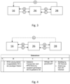
- a system 10 according to the invention for processing sheet metal is shown schematically.
- the system comprises a sheet metal processing machine 14, an RFID reader 18 and a device 16 for detecting a sheet metal processing means in the sheet metal processing machine 14.
- the sheet metal processing machine 14 is a machine for processing relatively thick sheet metal parts made of steel or stainless steel.
- the sheet metal 12 (workpiece) is processed one after the other at the sheet metal processing stations 20a, 20b, 20c.
- the sheet metal processing machine 14 can be a deburring machine.
- the first processing station 20a is designed as a sanding belt unit, with a sanding belt being provided as the sheet metal processing means 24a, which rotates endlessly and is driven by an electric motor.
- the second processing station 20b is designed as a so-called brush unit with several sanding brushes as the sheet metal processing means 24b. For example, some of the sanding brushes rotate in the same direction and some in the opposite direction around their horizontal axis. At the same time, it is possible for the sanding brushes to rotate around a vertical axis. This results in a multi-rotation movement of the sanding brushes.
- the third processing station 20c comprises, in the embodiment shown, another wide-band sanding belt as Sheet metal processing means 24c.
- the sheet metal 12 to be processed is placed on the conveyor belt 22 and runs through the sheet metal processing machine 14 from left to right in the illustration.
- the sheet metal is deburred using the first sanding belt unit.
- the edges are then rounded and the surface brushed using the brush unit.
- the surface is finely ground using the sanding belt unit at the third sheet metal processing station 20c, thereby giving it a finish.
- the sheet metal processing machine 14 comprises a machine system 26 for configuring and setting the behavior and the processing process to be carried out, which can correspond in particular to a machine control system.
- the sheet metal processing machine 14 also comprises a display unit 28, which allows a machine operator to make settings or read out information.
- the machine operator usually specifies settings for the machine system 26 via the display unit 28.
- the display unit 28 can comprise a touchscreen display, for example.
- RFID transponders 30a, 30b, 30c are provided or attached or integrated on the sheet metal processing means 24a, 24b, 24c, which can be read using the RFID reader 18.
- the RFID reader 18 is connected to a total of three antennas 34a, 34b, 34c, which are each arranged at the sheet metal processing stations 20a, 20b, 20c.
- the RFID transponders 30a, 30b, 30c are read within the respective sheet metal processing station, with the orientation of the various antennas 34a, 34b, 34c preferably being selected such that only RFID transponders within the individual processing stations can be read and RFID transponders in neighboring sheet metal processing stations cannot be read.
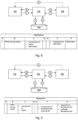
- FIG 2 is a schematic view of a device 16 according to the invention for detecting a sheet metal processing means in a sheet metal processing machine shown.
- a sheet metal processing means 24a, 24b, 24c is recognized and, based on this, the machine system 26 is controlled.
- the device comprises an RFID unit 36, an evaluation unit 38, a machine interface 40 and an optional database connection 42.
- the various units can be partially or completely implemented in software and/or hardware.
- the units can be designed as processors, processor modules or also as software for a processor.
- the device 16 can, for example, be designed in the form of an additional device for a sheet metal processing machine or as software for a machine system of a sheet metal processing machine.
- the device 16 can be implemented in software, with the software being executed on a machine system of a sheet metal processing machine.
- the device 16 it is also possible for the device 16 to be designed as an additional device that communicates with a machine system, a sheet metal processing machine and an RFID reader.
- the RFID reader and the device 16 can be arranged in a control cabinet.
- the RFID unit 36 is in communication with the RFID reader and is designed to receive a reading signal.
- the reading signal includes information about an RFID transponder on a sheet metal processing device.
- the reading signal can include an ID of the RFID transponder.
- the evaluation unit 38 is used to determine sheet metal processing equipment data.
- the previously received reading signal from the RFID reader serves as the basis for this.
- the evaluation unit 38 can query a memory of the device 16 that contains previously recorded data. It is also possible to query a database that contains information on sheet metal processing equipment.
- the key for the query is, for example, the ID of the recognized sheet metal processing equipment.
- the machine interface 40 is used for communication with the machine system of the sheet metal processing machine.
- the machine system is controlled using previously determined sheet metal processing equipment data.
- individual functions of the sheet metal processing machine can be controlled (specifying a processing time, a force, a speed, etc.). It is also possible for a current process to be started or interrupted or for another reaction to be triggered.
- the (optional) database connection 42 is used for communication with a database that can be located externally or internally.
- the database connection 42 can correspond, for example, to a network or Internet connection, via which communication can be established with a remotely located database.
- a database of the manufacturer of the sheet metal processing machine can be accessed via an Internet connection.
- the database connection 42 can also communicate with a database of the machine system or address it.
- the inventive device 16 is in communication with the machine system 26, which enables interaction with a machine operator via the display unit 28.
- the letters A to E identify the various possible data streams or information flows. It is indicated that a data stream A can also be provided between the display unit 28 and the inventive device 16.
- Such a data stream can be made possible, for example, by the device 16 addressing a display, possibly via the machine system 26.
- a sensor can be arranged on this door or flap in order to detect opening/closing. This sensor can, for example, be in communication with the machine system. With each opening/closing, the machine system can initiate a measurement or detection of the sheet metal processing means in the machine by communicating with the inventive device 16.
- information determined by the device 16 according to the invention can be provided to the machine system 26, for example. It can be specified, for example, at which sheet metal processing station the sheet metal processing tool was used. It can also be specified which type of sheet metal processing tool is affected and at which sheet metal processing station the change took place. It is possible that an interaction with the machine operator (for example via the display unit 28) takes place to initiate the reading process. The machine operator can be asked, for example, whether an RFID reading should be triggered.
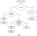
- FIG 4 A process for detecting whether the correct sheet metal processing tool is being used is shown schematically.
- the device 16 according to the invention usually has no memory of which sheet metal processing tool was used at a previous point in time. Usually, only a snapshot can be taken of which sheet metal processing tool is in the machine at the time of measurement. The last sheet metal processing tool detected or the sheet metal processing tool that should be in the sheet metal processing machine at that time is stored in the machine system 26. The device 16 therefore receives the information from the machine system 26 as to which sheet metal processing tool should be in the machine and compares this information with the detected sheet metal processing tool. The comparison takes place after each new RFID reading. If the If the sheet metal processing means detected by the device 16 according to the invention does not correspond to the sheet metal processing means stored in the machine system 26, a notification can be displayed on the display unit 28.
- the notification can, for example, prompt the machine operator to confirm that a change in the sheet metal processing tool has taken place.
- the machine operator can, for example, be shown the recognized sheet metal processing tool with its parameters. The machine operator can therefore check whether the sheet metal processing tool recognized by the device according to the invention corresponds to the sheet metal processing tool actually in the machine. The machine operator can then confirm that a change has taken place or reject it. If a change is not confirmed, no automatic change takes place. If, however, the operator confirms the change, an automated (system-side) processing tool change takes place. The sheet metal processing tool stored in the machine system 26 is replaced by the recognized sheet metal processing tool.
- FIG 6 an approach for counting abrasives in the respective sheet metal processing stations is shown.
- the detected sheet metal processing tools can be counted and the existing number can be compared with a required number. This is relevant if, for example, several individual sheet metal processing tools are used in a sheet metal processing station.
- the detection can distinguish three cases in particular. If more sheet metal processing tools are detected than are intended for the sheet metal processing station, a corresponding warning can be issued to a machine operator. The machine operator can then be given the choice, for example, of whether the measurement should be repeated or whether a manual change of the sheet metal processing tool should be initiated. If fewer transponders are detected than intended for the sheet metal processing station, the machine operator can also be given information reflecting this.
- the detection of too few sheet metal processing tools in a sheet metal processing station either indicates that too few sheet metal processing tools have been equipped. Alternatively, there may be a defective RFID transponder. It is also possible that a readout is prevented due to contamination in the sheet metal processing machine. For example, the machine operator can be suggested to take another measurement via the display unit. If the second measurement then gives the same result, the machine operator can be asked to check whether a sheet metal processing tool is missing or not. If the number of sheet metal processing tools detected is successfully compared with the number of sheet metal processing tools intended, this can also be displayed.
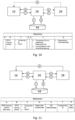
- FIG 7 a recognition of sheet metal processing equipment is illustrated.
- sheet metal processing stations or sheet metal processing machines where several individual sheet metal processing tools or a multi-part sheet metal processing tool must be present in order to fully equip the sheet metal processing station and provide the desired function (see, for example, the illustration in Figure 1 with the multi-part sheet metal processing means 20b).
- it can be a set of sheet metal processing means.
- Such a set can advantageously be viewed as a unit. The unit is only considered complete and complete if all the different RFID transponders of the sheet metal processing means in a set can be read. If an RFID transponder cannot be read, the set cannot fulfill the corresponding functionality. If this is detected by the device according to the invention, a blockade can be initiated via the machine interface.
- the set can be defined, for example, after an initial wear measurement and can be considered a set as long as the sheet metal processing means is not blocked. After an initial In order to measure wear, the various RFID transponders read can be stored as a set in a database.
- the machine system comprises a sheet metal processing tool selection unit, by means of which a suggestion for a sheet metal processing tool to be used can be provided in an automated manner.
- a suggestion for a sheet metal processing tool to be used can be provided in an automated manner.
- the device according to the invention it can be achieved, for example, that a corresponding setting of the sheet metal processing machine can only be made in this case if the recognized sheet metal processing tool also corresponds to the suggested sheet metal processing tool.
- the device according to the invention it is also possible for the device according to the invention to create a list of which sheet metal processing tools are available and how many operating hours they have already been used (indication of wear). It is then possible for the sheet metal processing tool selection unit to suggest those sheet metal processing tools that are already present and available.
- FIG 8 is a schematic representation of an approach for storing data from the manufacturer of the sheet metal processing tool on an RFID transponder.
- Different sheet metal processing tools can differ.
- wide-band sanding belts can differ in their length due to manufacturing tolerances. This can be critical, especially with precise machines, since there is often no way of automatically compensating for such a difference in the sheet metal processing machine. It is possible to determine a diameter of a sanding belt using a measuring funnel. If this variable is known, it can be compensated by the machine system. In this respect, it is fundamentally possible for a length and a thickness of a wide-band sanding belt to be determined manually (or individually for this specific sheet metal processing tool) before delivery and stored on the corresponding RFID transponder.
- this information can then be accessed and transmitted from the device 16 according to the invention to the machine system 26. It is then possible for the corresponding information is stored in a database 44.
- the database 44 is in communication with the machine system (further data streams F and G). It is also possible for the database to be in direct communication with the device 16 according to the invention. Information specifically or individually assigned to a sheet metal processing tool can therefore be determined, stored and/or used.
- FIG 9 is a schematic representation of an approach for storing an operating time of the sheet metal processing tool on the respective RFID transponder or in a database 44 with a corresponding transponder ID as an assignment.
- the current operating hours can therefore be determined by the machine system 26 and passed on to the device 16 according to the invention. This enables a number of operating hours of the sheet metal processing tool to be determined.
- a notification can be issued to the machine operator via the display unit 28, for example. This notification can be used to remind the machine operator to order a new sheet metal processing tool, for example.
- a QR code with a corresponding order link can be integrated directly into the output. It is also possible to trigger an automated order directly.
- FIG 10 A further embodiment is shown in which wear data, for example from a wear measurement, is stored on an RFID transponder or in a database with a corresponding transponder ID as an assignment.
- wear data for example from a wear measurement
- the wear data from the machine system should be stored. This is particularly important for rotor brushes as sheet metal processing tools. interesting. By storing wear data, a significantly shortened wear measurement or even no wear measurement at all may be necessary when the sheet metal processing tool is reloaded.
- FIG 11 a schematic approach for storing data about the sheet metal processing tool is shown.
- a type or grain size of an abrasive can be stored.
- a sheet metal processing tool can thus be given a type of electronic nameplate.
- the known data associated with the sheet metal processing tool can be made available to a user when read out. The reading can take place in a sheet metal processing station in the sheet metal processing machine. It is also possible, however, for a separate RFID antenna to be provided for this purpose.
- a suitable type of application can also be stored.
- the specified data can either be stored directly on the RFID transponder or obtained from a database that is either directly connected to the device 16 according to the invention or is made available via the machine system 26.
- transponder data and the associated information can be stored in a local database.
- This database contains the various RFID transponders and their IDs that are approved for use with a sheet metal processing machine. In addition, these RFID transponders are blocked after a predefined period of operation.
- This local database can be updated, for example, when the sheet metal processing machine is being serviced. It is also possible to use a remote, internet-based database.
- FIG. 12 A method according to the invention for detecting a sheet metal processing tool in a sheet metal processing machine is shown schematically.
- the method comprises steps of receiving S10 a read signal, determining S12 sheet metal processing tool data and controlling S14 a machine system.
- the method can be implemented in software, for example which is carried out on a machine system of a sheet metal working machine.
- a computer program can be stored/distributed on a non-volatile data carrier, for example on an optical memory or on a semiconductor drive (SSD).
- a computer program can be distributed together with hardware and/or as part of hardware, for example via the Internet or via wired or wireless communication systems. Reference signs in the claims are not to be understood as limiting.
Landscapes
- Engineering & Computer Science (AREA)
- Mechanical Engineering (AREA)
- Physics & Mathematics (AREA)
- General Physics & Mathematics (AREA)
- Automation & Control Theory (AREA)
- Manufacturing & Machinery (AREA)
- Human Computer Interaction (AREA)
- Artificial Intelligence (AREA)
- Computer Vision & Pattern Recognition (AREA)
- Theoretical Computer Science (AREA)
- Toxicology (AREA)
- Health & Medical Sciences (AREA)
- General Health & Medical Sciences (AREA)
- Electromagnetism (AREA)
- Computer Security & Cryptography (AREA)
- Computer Networks & Wireless Communication (AREA)
- General Factory Administration (AREA)
Priority Applications (3)
| Application Number | Priority Date | Filing Date | Title |
|---|---|---|---|
| EP23157232.2A EP4417362A1 (fr) | 2023-02-17 | 2023-02-17 | Dispositif et procédé de détection d'un moyen de traitement de tôle dans une machine de traitement de tôle |
| US18/430,306 US20240280957A1 (en) | 2023-02-17 | 2024-02-01 | Device and method for recognising a sheet metal processing means in a sheet metal processing machine |
| CN202410174878.0A CN118513958A (zh) | 2023-02-17 | 2024-02-07 | 用于识别钣金加工机器中的钣金加工工具的装置和方法 |
Applications Claiming Priority (1)
| Application Number | Priority Date | Filing Date | Title |
|---|---|---|---|
| EP23157232.2A EP4417362A1 (fr) | 2023-02-17 | 2023-02-17 | Dispositif et procédé de détection d'un moyen de traitement de tôle dans une machine de traitement de tôle |
Publications (1)
| Publication Number | Publication Date |
|---|---|
| EP4417362A1 true EP4417362A1 (fr) | 2024-08-21 |
Family
ID=85283885
Family Applications (1)
| Application Number | Title | Priority Date | Filing Date |
|---|---|---|---|
| EP23157232.2A Pending EP4417362A1 (fr) | 2023-02-17 | 2023-02-17 | Dispositif et procédé de détection d'un moyen de traitement de tôle dans une machine de traitement de tôle |
Country Status (3)
| Country | Link |
|---|---|
| US (1) | US20240280957A1 (fr) |
| EP (1) | EP4417362A1 (fr) |
| CN (1) | CN118513958A (fr) |
Citations (5)
| Publication number | Priority date | Publication date | Assignee | Title |
|---|---|---|---|---|
| WO2018160658A2 (fr) * | 2017-02-28 | 2018-09-07 | 3M Innovative Properties Company | Produit abrasif communiquant avec un outil abrasifs |
| DE212017000255U1 (de) * | 2017-12-18 | 2019-08-06 | Lanuss Industrial Equipment (Suzhou) Co., Ltd. | Entgratungsmaschine |
| DE102018121139B3 (de) * | 2018-08-29 | 2019-09-26 | Vsm Vereinigte Schmirgel- Und Maschinen-Fabriken Ag | Endlos-Schleifband für eine Schleifmaschine |
| US20200039027A1 (en) * | 2018-08-02 | 2020-02-06 | Saint-Gobain Abrasives, Inc. | Abrasive article including a wear detection sensor |
| DE202020107308U1 (de) | 2020-12-16 | 2021-02-09 | Arku Maschinenbau Gmbh | Maschine zum Bearbeiten von Blechteilen |
-
2023
- 2023-02-17 EP EP23157232.2A patent/EP4417362A1/fr active Pending
-
2024
- 2024-02-01 US US18/430,306 patent/US20240280957A1/en active Pending
- 2024-02-07 CN CN202410174878.0A patent/CN118513958A/zh active Pending
Patent Citations (5)
| Publication number | Priority date | Publication date | Assignee | Title |
|---|---|---|---|---|
| WO2018160658A2 (fr) * | 2017-02-28 | 2018-09-07 | 3M Innovative Properties Company | Produit abrasif communiquant avec un outil abrasifs |
| DE212017000255U1 (de) * | 2017-12-18 | 2019-08-06 | Lanuss Industrial Equipment (Suzhou) Co., Ltd. | Entgratungsmaschine |
| US20200039027A1 (en) * | 2018-08-02 | 2020-02-06 | Saint-Gobain Abrasives, Inc. | Abrasive article including a wear detection sensor |
| DE102018121139B3 (de) * | 2018-08-29 | 2019-09-26 | Vsm Vereinigte Schmirgel- Und Maschinen-Fabriken Ag | Endlos-Schleifband für eine Schleifmaschine |
| DE202020107308U1 (de) | 2020-12-16 | 2021-02-09 | Arku Maschinenbau Gmbh | Maschine zum Bearbeiten von Blechteilen |
Also Published As
| Publication number | Publication date |
|---|---|
| US20240280957A1 (en) | 2024-08-22 |
| CN118513958A (zh) | 2024-08-20 |
Similar Documents
| Publication | Publication Date | Title |
|---|---|---|
| EP2494475B1 (fr) | Serveur d'un réseau d'ordinateurs | |
| EP2771747B1 (fr) | Procédé de lecture d'un code de modèle bidimensionnel et de représentation et utilisation de données, appareil portatif pour réaliser le procédé et procédé de réalisation d'un code de modèle bidimensionnel | |
| DE102018119277A1 (de) | Datenverarbeitungseinrichtung einer produktionsvorrichtung | |
| DE60107740T2 (de) | Vorrichtung und verfahren zur benachrichtigung eines maschineführers über die notwendigkeit einer präventiven wartung | |
| WO2018202336A1 (fr) | Procédé et dispositif pour le façonnage incrémental d'une pièce métallique | |
| EP2796251A2 (fr) | Couteau de découpe d'aliment doté d'un transpondeur radio | |
| WO2016165940A1 (fr) | Formation de familles d'équipements pour un système d'usinage comportant une machine-outil | |
| EP3014584A1 (fr) | Système pour détecter des composants d'un véhicule | |
| EP2664973B1 (fr) | Procédé de gestion des données outil | |
| DE102010054744A1 (de) | Schneidwerkzeug zu gewerblichen Zwecken in Kombination mit einer EDV-Anlage | |
| WO2003017015A1 (fr) | Procede d'identification de modules ou d'unites modulaires et systeme d'identification et/ou de diagnostic d'un module ou d'une unite modulaire comprenant une pluralite de composants individuels | |
| DE102017200365B4 (de) | Verfahren und Vorrichtung zum Richten eines Metallbandes | |
| EP2616223A1 (fr) | Procédé permettant d'éviter les défaillances et les pièces défectueuses lors du fonctionnement d'une machine de fabrication | |
| DE102011108361A1 (de) | Server eines Computernetzwerks | |
| EP4417362A1 (fr) | Dispositif et procédé de détection d'un moyen de traitement de tôle dans une machine de traitement de tôle | |
| EP3803727B1 (fr) | Procédé et système pour fournir des protocoles de processus pour des objets physiques | |
| DE102017103866A1 (de) | Verfahren zum Betreiben einer Werkstückbearbeitungsanlage, sowie Werkstückbearbeitungsanlage | |
| DE10151854A1 (de) | Wertdokumentbearbeitungsvorrichtung, Verfahren zur Funktionsprüfung, Justierung und/oder Kalibrierung der Wertdokumentbearbeitungsvorrichtung und Testmedien zur Durchführung des Verfahrens | |
| DE102021129168A1 (de) | Systeme und verfahren zur flexiblen modularen montagefertigung | |
| DE10357177A1 (de) | Schleifvorrichtung | |
| WO2014206770A1 (fr) | Procédé et dispositif pour actualiser le logiciel d'un appareil de commande de véhicule à moteur | |
| WO2021148505A1 (fr) | Procédé et système de caractérisation automatique d'une pièce à usiner pendant un processus d'usinage utilisant une machine-outil | |
| EP2395405B1 (fr) | Dispositif et procédé destinés à la surveillance d'outils | |
| EP4122313B1 (fr) | Procédé de détermination de l'état d'usure d'une contre-lame agencée sur un porte-contre-lame, ainsi que ramasseuse-hacheuse autonome | |
| DE102021129094A1 (de) | Verfahren zum Ermitteln von Ersatzteilbedarf |
Legal Events
| Date | Code | Title | Description |
|---|---|---|---|
| PUAI | Public reference made under article 153(3) epc to a published international application that has entered the european phase |
Free format text: ORIGINAL CODE: 0009012 |
|
| STAA | Information on the status of an ep patent application or granted ep patent |
Free format text: STATUS: THE APPLICATION HAS BEEN PUBLISHED |
|
| AK | Designated contracting states |
Kind code of ref document: A1 Designated state(s): AL AT BE BG CH CY CZ DE DK EE ES FI FR GB GR HR HU IE IS IT LI LT LU LV MC ME MK MT NL NO PL PT RO RS SE SI SK SM TR |
|
| STAA | Information on the status of an ep patent application or granted ep patent |
Free format text: STATUS: REQUEST FOR EXAMINATION WAS MADE |
|
| 17P | Request for examination filed |
Effective date: 20250217 |