EP4420973A1 - Verbesserte folie für ein flossen- oder segel- oder kiel- oder windmühlenflügel - Google Patents
Verbesserte folie für ein flossen- oder segel- oder kiel- oder windmühlenflügel Download PDFInfo
- Publication number
- EP4420973A1 EP4420973A1 EP23315039.0A EP23315039A EP4420973A1 EP 4420973 A1 EP4420973 A1 EP 4420973A1 EP 23315039 A EP23315039 A EP 23315039A EP 4420973 A1 EP4420973 A1 EP 4420973A1
- Authority
- EP
- European Patent Office
- Prior art keywords
- foil
- foil section
- section
- sail
- section according
- Prior art date
- Legal status (The legal status is an assumption and is not a legal conclusion. Google has not performed a legal analysis and makes no representation as to the accuracy of the status listed.)
- Pending
Links
Images


Classifications
-
- B—PERFORMING OPERATIONS; TRANSPORTING
- B63—SHIPS OR OTHER WATERBORNE VESSELS; RELATED EQUIPMENT
- B63B—SHIPS OR OTHER WATERBORNE VESSELS; EQUIPMENT FOR SHIPPING
- B63B1/00—Hydrodynamic or hydrostatic features of hulls or of hydrofoils
- B63B1/16—Hydrodynamic or hydrostatic features of hulls or of hydrofoils deriving additional lift from hydrodynamic forces
- B63B1/24—Hydrodynamic or hydrostatic features of hulls or of hydrofoils deriving additional lift from hydrodynamic forces of hydrofoil type
- B63B1/248—Shape, hydrodynamic features, construction of the foil
-
- B—PERFORMING OPERATIONS; TRANSPORTING
- B63—SHIPS OR OTHER WATERBORNE VESSELS; RELATED EQUIPMENT
- B63B—SHIPS OR OTHER WATERBORNE VESSELS; EQUIPMENT FOR SHIPPING
- B63B1/00—Hydrodynamic or hydrostatic features of hulls or of hydrofoils
- B63B1/16—Hydrodynamic or hydrostatic features of hulls or of hydrofoils deriving additional lift from hydrodynamic forces
- B63B1/24—Hydrodynamic or hydrostatic features of hulls or of hydrofoils deriving additional lift from hydrodynamic forces of hydrofoil type
- B63B1/28—Hydrodynamic or hydrostatic features of hulls or of hydrofoils deriving additional lift from hydrodynamic forces of hydrofoil type with movable hydrofoils
- B63B1/285—Hydrodynamic or hydrostatic features of hulls or of hydrofoils deriving additional lift from hydrodynamic forces of hydrofoil type with movable hydrofoils changing the angle of attack or the lift of the foil
-
- B—PERFORMING OPERATIONS; TRANSPORTING
- B63—SHIPS OR OTHER WATERBORNE VESSELS; RELATED EQUIPMENT
- B63B—SHIPS OR OTHER WATERBORNE VESSELS; EQUIPMENT FOR SHIPPING
- B63B41/00—Drop keels, e.g. centre boards or side boards ; Collapsible keels, or the like, e.g. telescopically; Longitudinally split hinged keels
-
- B—PERFORMING OPERATIONS; TRANSPORTING
- B63—SHIPS OR OTHER WATERBORNE VESSELS; RELATED EQUIPMENT
- B63H—MARINE PROPULSION OR STEERING
- B63H16/00—Marine propulsion by muscle power
- B63H16/04—Oars; Sculls; Paddles; Poles
-
- B—PERFORMING OPERATIONS; TRANSPORTING
- B63—SHIPS OR OTHER WATERBORNE VESSELS; RELATED EQUIPMENT
- B63H—MARINE PROPULSION OR STEERING
- B63H9/00—Marine propulsion provided directly by wind power
- B63H9/04—Marine propulsion provided directly by wind power using sails or like wind-catching surfaces
- B63H9/06—Types of sail; Constructional features of sails; Arrangements thereof on vessels
- B63H9/061—Rigid sails; Aerofoil sails
-
- B—PERFORMING OPERATIONS; TRANSPORTING
- B64—AIRCRAFT; AVIATION; COSMONAUTICS
- B64C—AEROPLANES; HELICOPTERS
- B64C3/00—Wings
- B64C3/38—Adjustment of complete wings or parts thereof
- B64C3/44—Varying camber
- B64C3/48—Varying camber by relatively-movable parts of wing structures
-
- B—PERFORMING OPERATIONS; TRANSPORTING
- B64—AIRCRAFT; AVIATION; COSMONAUTICS
- B64C—AEROPLANES; HELICOPTERS
- B64C3/00—Wings
- B64C3/38—Adjustment of complete wings or parts thereof
- B64C3/44—Varying camber
- B64C2003/445—Varying camber by changing shape according to the speed, e.g. by morphing
Definitions
- the present invention generally relates to a foil section for use as aerofoil or hydrofoil.
- the present invention further relates to a sail or fin or keel or windmill blade comprising such foil section.
- sails are made from a combination of woven materials-including canvas or polyester cloth, laminated membranes or bonded filaments-usually in a three- or four-sided shape.
- a sail provides propulsive force to propel sailing ships, sailboats, surfboards, ice boats, etc. via a combination of lift and drag, depending on its angle of attack, which is the angle with respect to the apparent wind.
- the sail may act more or less as an airfoil, generating propulsive force as air passes along its surface (cfr. an airplane wing).
- an airfoil should ideally have adaptive camber, i.e. camber is the asymmetry between the two acting surfaces of an airfoil, namely the convex side and the concave side, depending on tack and wind speed, as the airfoil becomes more efficient with greater curvature on the downwind side.
- camber is the asymmetry between the two acting surfaces of an airfoil, namely the convex side and the concave side, depending on tack and wind speed, as the airfoil becomes more efficient with greater curvature on the downwind side.
- a traditional sail's camber line indeed changes when sailing upwind because the sail curvature indeed reverses upon changing the windward side.
- a conventional sail simply fills in with wind on each tack, it does not perform well compared to a well-designed airfoil and may result in disturbances at certain points of sail.
- keels serve two purposes: 1) minimizing the lateral motion of the vessel under sail (leeway) and 2) as a counterweight to the lateral force of the wind on the sail(s) that causes rolling to the side (heeling).
- the keel uses the forward motion of the boat to generate lift to counteract the leeward force of the wind.
- the keel acting as an hydrofoil ideally should have adaptive camber and reversible curvature depending on the point of sail and the speed.
- FR2773773A1 (BALLU ) provides sail having a series of semi-rigid ribs (10), placed along an axis perpendicular to the mast, for maintaining a pre-specified gap between two sail casings.
- the sail asymmetry is reversible.
- EP3464054B1 SOFTWING ) describes a sail including two sail surfaces spaced apart from one another, and an adjustable skeleton device disposed between the surfaces.
- the skeleton device provides for reversibility of the sail.
- US9944356B1 (WIGLEY ) describing a hydrofoil, in particular a keel for a sailboat, with reversible asymmetry comprising a skin that forms a foil contour is at least partially attached to and wrapped around a leading edge structure so two edges of the skin form the trailing edge of the fluid foil.
- a general drawback of the above references is that a sail or keel shaped by an internal elastic reversible profile or frame is a complex structure which obviously requires complex and costly production and assembly.
- the present invention is directed to a foil section consisting of a hollow profile having a foil shaped axial cross section, characterized in that the hollow profile is made of self-supporting elastic plastic.
- the foil section consists of a one-piece elastomeric or thermoplastic plastic.
- the present invention is directed to a sail or sail section or sail assembly comprising one or more of the foil sections.
- the present invention is directed to a keel or keel section or keel assembly comprising one or more of the foil sections.
- the present invention is directed to diving fins comprising the foil section as described, to paddles or rowing oars comprising the foil section as described, and to windmill blades comprising the foil section as described.
- the present invention is directed to a foil section consisting of a hollow profile having a foil shaped axial cross section, characterized in that the hollow profile is made of self-supporting elastic plastic.
- a foil section is understood as a solid object with any such shape that when placed in a moving fluid at a suitable angle of attack the lift (force L generated perpendicular to the fluid flow) is substantially larger than the drag (force D generated parallel to the fluid flow) (see FIG 1 ).
- the foil If the fluid is a gas, the foil is called an airfoil or aerofoil, and if the fluid is water the foil is called a hydrofoil.
- a foil generates lift primarily because of its shape and angle of attack. When oriented at a suitable angle, the foil deflects the oncoming fluid, resulting in a force on the foil in the direction opposite to the deflection.
- a hollow profile having a foil shaped axial cross section is understood as the profile having an axial perimeter corresponding to an axial perimeter of a foil. More particularly, the hollow profile may have an outer shell that in axial cross section has the shape corresponding to an axial cross section of an outer shell of a foil, e.g. an axial perimeter of a plane wing or an axial perimeter of a dolphin flipper fin.
- self-supporting is understood as the hollow profile being sufficiently rigid not to collapse if not supported.
- the foil section may have a pressure face (PF) (i.e. intrados or concave) and a suction face (SF) (i.e. extrados or convex) and is adapted to reversibly bend thereby alternating the pressure face and the suction face within the fluid, i.e air or water.
- PF pressure face
- SF suction face
- the hollow profile made of self-supporting elastic plastic has to be sufficiently rigid to be self-supporting and at the same time sufficiently elastic to allow adaptive camber and reversible curvature.
- the foil section may be adapted to reversibly bend in an autonomous non-motorized way to an aero- or hydro-dynamically efficient shape.
- the leading edge (a) of the foil may be have any shape as suitable for use as a sail or keel, and in particular a circular shape.
- the trailing edge (b) may have substantially sharp end constituted by two converging side walls (c).
- the hollow profile may be internally supported by a number of supporting inner ribs (d). These ribs connect the two converging side walls (c) and maintaining the mutual distance between these walls in any state of curvature of the foil.
- the foil section may have a elastic hollow profile constituted by the side walls, the leading edge (a) and the trailing edge (b), wherein the convergent side walls (c) are connected by the inner ribs (d) aligned underneath the profile's outer shell.
- the inner ribs may support the hollow profile in a direction with an angle between 30° and 150° relative to a straight line connecting the leading edge (a) with a trailing edge (b) in non-curved state.
- angle is between 60° and 120°, or between 75° and 105°, or as illustrated in FIG 4 about 90° in non-curved state.
- the inner ribs (d) extend in a lateral plane from a top (f) of the foil section to the bottom (e) of the foil section.
- the inner ribs constitute in fact a number of beams of which the longitudinal side walls connect the two converging side walls (c) and maintaining the mutual distance between these walls in any state of curvature of the foil section.
- the inner ribs may be interrupted once or more in a lateral plane from a top (f) of the foil section to the bottom (e) of the foil section. They may even be interrupted in the lateral plane so many times as to constitute in fact a number of axially elongated bars connecting the two converging side walls (c) and maintaining the mutual distance between these walls in any state of curvature of the foil section.
- the inner ribs are adapted to follow the reversible curvature of the foil section. Therefore, the connection of the ribs to the side walls may be made of a elastic material adapted to reversibly deform and/or bend allowing the ribs to reversibly changing its position relative to each side wall. Preferably, the inner ribs are made as a whole of such elastic material.
- the side walls may have a cross-sectional thickness of between 0,1 and 10 mm, or between 0,1 and 5mm, or between 0,1 and 2mm depending on the material used and the required elasticity and reversibility.
- the cross-sectional thickness of the ribs may be as well between 0,1 and 10 mm, or between 0,1 and 5mm, or between 0,1 and 2mm depending on the material used and the required elasticity and reversibility.
- the number of ribs per 10 centimetres in longitudinal direction of the hollow profile may be between 2 and 20, or between 2 and 15, or between 2 and 10.
- the elastic hollow profile constituted by the side walls, the leading edge and the trailing edge may be made of any material providing sufficient elastic deformation, while not suffering from plastic deformation.
- Such material should have sufficiently low modulus of elasticity (also called Young's modulus) , or in other words sufficiently high modulus of resilience, i.e. the modulus of resilience is the maximum amount of volume that a material will elastically deform before becoming permanently deformed.
- modulus of resilience is the maximum amount of volume that a material will elastically deform before becoming permanently deformed.
- Young's modulus As known in the state of the art, elasticity is the ability of a material to absorb energy when it is deformed elastically, and release that energy upon unloading. Elasticity is the ability of a material to withstand elastic deformation without deforming plastically. In other words, elasticity involves the stretching of atomic bonds prior to the breaking of the bonds.. Further, such material should have sufficient tensile strength, sufficient impact resistance, sufficient abrasion resistance, and should be sufficiently waterproof.
- the hollow profile of the foil section may be made of a self-supporting elastic plastic.
- the hollow profile may be made of an elastomer or an elastomer-like thermoplastic material such as silicone rubber (SBR), polyurethane rubber (PUR rubber), latex, styrene-butadiene rubber (SBR), ethylene propylene diene methylene (EPDM), chlorosulfonated polyethylene (CSM), acrylated aliphatic urethane (eg. Resione F80 type) etc.
- silicone rubber SBR
- PUR rubber polyurethane rubber
- SBR polyurethane rubber
- EPDM ethylene propylene diene methylene
- CSM chlorosulfonated polyethylene
- acrylated aliphatic urethane eg. Resione F80 type
- the hollow profile may be made of soft thermoplastics such as Polypropylene (PP), soft Polyvinyl Chloride (PVC), polyamides (such as PA12 or PA11), Teflon (PTFE).
- soft thermoplastics such as Polypropylene (PP), soft Polyvinyl Chloride (PVC), polyamides (such as PA12 or PA11), Teflon (PTFE).
- suitable self-supporting elastic plastic may have a Young's modulus between 1 and 2000MPa, or between 1 and 1500MPa, or between 1 and 1000MPa as measured in accordance with ISO527.
- suitable self-supporting elastic plastic may have a tensile strength between 1 and 50MPa as measured in accordance with ISO527.
- the self-supporting elastic plastic may be an elastomer or an elastomer-like thermoplastic having a Young's modulus below 15MPa, or below 10MPa as measured in accordance with ISO527.
- Further suitable elastomers or elastomer-like thermoplastics may have a tensile strength between 1 MPa and 30MPa, or between 1 MPa and 20MPa, or between 1 MPa and 15MPa as measured in accordance with ISO527.
- the self-supporting elastic plastic may be a soft thermoplastic having a Young's modulus between 1 and 2000MPa, or between 1 and 1500MPa, or below 1000MPa, or below 500MPa as measured in accordance with ISO527.
- Further soft thermoplastics may have a tensile strength between 10MPa and 50MPa, or between 20MPa and 50MPa, or between 30MPa and 50MPa as measured in accordance with ISO527.
- the elastomeric or thermoplastic material may be fibre reinforced, eg. carbon or glass fibers.
- the orientation of the fibers would be such that they do not overly inhibit the strain required to bend the foil section but such that the fibers can contribute to its rigidity in other directions.
- the inner ribs and the hollow profile are made of the same self-supporting elastic plastic.
- the advantage thereof is lower production cost.
- the foil section consists of a one-piece elastomeric or thermoplastic material.
- the advantage thereof is even lower production cost since the foil section can be manufactured as a whole by a suitable plastic converting process, such as for example extrusion or injection molding, or 3D printing.
- manufacturing one-piece foil sections obviously results in very low or zero assembly cost.
- a sail or sail section comprising a foil section or a number of foil sections as described above.
- a sail may be constituted by one sail section comprising one foil section as described above, or may be constituted by a number of connected sail sections and suitable gear for connecting and positioning the sail sections.
- a sail assembly may comprise at least two of said sail sections, wherein the size of the higher section in risen state is smaller than the size of the lower section such that in collapsed state the higher section fits into the lower section ( FIG 4B ).
- the inner ribs of each sail section (or foil section) are positioned such as to allow the higher section to fit in the lower section.
- a fin or keel or keel section (eg. for a sailboat or surfer board) is provided comprising a foil section or a number of foil sections as described above.
- a fin or keel may be constituted by one fin section or keel section comprising one foil section as described above, or may be constituted by a number of connected fin or keel sections and suitable gear for connecting and positioning the keel sections.
- a keel assembly may comprise at least two of said keel sections, wherein the size of the lower section in immersed state is smaller than the size of the higher section such that in collapsed state the lower section fits into the higher section ( FIG 5B ).
- the inner ribs of each keel section or foil section
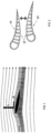
- FIG 6 a fin for a surfboard is illustrated comprising between 10 and 100 foil sections according to the present invention.
- the present invention is directed to diving fins comprising the foil section as described, and to paddles or rowing oars comprising the foil section as described.
- a foil section according to present invention may be used in all application wherein reversible foils may provide benefits, such as windmill blades
Landscapes
- Engineering & Computer Science (AREA)
- Mechanical Engineering (AREA)
- Chemical & Material Sciences (AREA)
- Combustion & Propulsion (AREA)
- Ocean & Marine Engineering (AREA)
- Physics & Mathematics (AREA)
- Fluid Mechanics (AREA)
- Aviation & Aerospace Engineering (AREA)
- Life Sciences & Earth Sciences (AREA)
- Sustainable Development (AREA)
- Sustainable Energy (AREA)
- Wind Motors (AREA)
Priority Applications (1)
| Application Number | Priority Date | Filing Date | Title |
|---|---|---|---|
| EP23315039.0A EP4420973A1 (de) | 2023-02-23 | 2023-02-23 | Verbesserte folie für ein flossen- oder segel- oder kiel- oder windmühlenflügel |
Applications Claiming Priority (1)
| Application Number | Priority Date | Filing Date | Title |
|---|---|---|---|
| EP23315039.0A EP4420973A1 (de) | 2023-02-23 | 2023-02-23 | Verbesserte folie für ein flossen- oder segel- oder kiel- oder windmühlenflügel |
Publications (1)
| Publication Number | Publication Date |
|---|---|
| EP4420973A1 true EP4420973A1 (de) | 2024-08-28 |
Family
ID=85601677
Family Applications (1)
| Application Number | Title | Priority Date | Filing Date |
|---|---|---|---|
| EP23315039.0A Pending EP4420973A1 (de) | 2023-02-23 | 2023-02-23 | Verbesserte folie für ein flossen- oder segel- oder kiel- oder windmühlenflügel |
Country Status (1)
| Country | Link |
|---|---|
| EP (1) | EP4420973A1 (de) |
Citations (8)
| Publication number | Priority date | Publication date | Assignee | Title |
|---|---|---|---|---|
| FR2773773A1 (fr) | 1998-01-21 | 1999-07-23 | Arnaud Ballu | Voilure a double surface pour engin a propulsion velique |
| US20110084174A1 (en) * | 2008-02-21 | 2011-04-14 | Cornerstone Research Group, Inc. | Passive adaptive structures |
| EP2327623B1 (de) * | 1999-04-01 | 2013-11-06 | Leif Kniese | Stuhl |
| WO2015093984A1 (en) * | 2013-12-19 | 2015-06-25 | Howard-Willis Guy | Water sports device and method of using the same |
| US20180057143A1 (en) * | 2016-08-24 | 2018-03-01 | Airbus (S.A.S.) | Airfoil extension for an aircraft wing |
| US9944356B1 (en) | 2009-03-25 | 2018-04-17 | Alexander T. Wigley | Shape shifting foils |
| EP3464054B1 (de) | 2016-05-24 | 2022-03-30 | SoftWing SA | Verstellbare rahmeneinrichtung für eine profilsegeleinrichtung und verstellbare profilsegeleinrichtung |
| US20220126979A1 (en) * | 2019-02-01 | 2022-04-28 | Guilhem COLOMBIÈS | Supporting structure with passively adaptable profile |
-
2023
- 2023-02-23 EP EP23315039.0A patent/EP4420973A1/de active Pending
Patent Citations (8)
| Publication number | Priority date | Publication date | Assignee | Title |
|---|---|---|---|---|
| FR2773773A1 (fr) | 1998-01-21 | 1999-07-23 | Arnaud Ballu | Voilure a double surface pour engin a propulsion velique |
| EP2327623B1 (de) * | 1999-04-01 | 2013-11-06 | Leif Kniese | Stuhl |
| US20110084174A1 (en) * | 2008-02-21 | 2011-04-14 | Cornerstone Research Group, Inc. | Passive adaptive structures |
| US9944356B1 (en) | 2009-03-25 | 2018-04-17 | Alexander T. Wigley | Shape shifting foils |
| WO2015093984A1 (en) * | 2013-12-19 | 2015-06-25 | Howard-Willis Guy | Water sports device and method of using the same |
| EP3464054B1 (de) | 2016-05-24 | 2022-03-30 | SoftWing SA | Verstellbare rahmeneinrichtung für eine profilsegeleinrichtung und verstellbare profilsegeleinrichtung |
| US20180057143A1 (en) * | 2016-08-24 | 2018-03-01 | Airbus (S.A.S.) | Airfoil extension for an aircraft wing |
| US20220126979A1 (en) * | 2019-02-01 | 2022-04-28 | Guilhem COLOMBIÈS | Supporting structure with passively adaptable profile |
Similar Documents
| Publication | Publication Date | Title |
|---|---|---|
| KR102768978B1 (ko) | 추진 장치 | |
| US4848258A (en) | Airfoil sailing system | |
| US20180148356A1 (en) | System for the production of hydrogen from sea water | |
| EP3269631B1 (de) | Segel mit veränderlichem profil | |
| KR920703385A (ko) | 수중익선의 수중익형/공중익형 구조물 및 수륙양용의 수상부양체 | |
| US20170369139A1 (en) | Deployable Shell Reversible Camber Sail System | |
| US10953969B2 (en) | Adjustable frame device for a profiled sail device, and adjustable profiled sail device | |
| WO1986004034A1 (en) | Rigging for a wind propelled craft | |
| US9199709B2 (en) | Frame device for a profiled sail device, and profiled sail device comprising at least one frame device | |
| EP4420973A1 (de) | Verbesserte folie für ein flossen- oder segel- oder kiel- oder windmühlenflügel | |
| US11208187B1 (en) | Sailing vessel | |
| US6019059A (en) | Overlap lifting fin | |
| US5896825A (en) | Dual hull watercraft | |
| US4860680A (en) | Sailboat with leeway reducing keel | |
| US20150197325A1 (en) | Wave Powered Water-Borne Vessel | |
| CN107074330B (zh) | 简化顺风换舷/迎风换舷操纵的索具 | |
| EP3216689B1 (de) | Strömungsprofil-anordnung, rumpf eines bootes oder eines schiffs, ruder und boot oder schiff | |
| US9114863B2 (en) | Aerodynamic fairing and flap for generating lift and methods of using the same | |
| CN116729608A (zh) | 一种蒙皮骨架式风帆以及无人风帆航行器 | |
| US5517934A (en) | Plastic boat hull and method of boat hull construction | |
| RU196940U1 (ru) | Надувная лодка с надувным дном высокого давления | |
| AU585930B2 (en) | Rigging for a wind propelled craft | |
| EP1535835A1 (de) | Flügelstruktur und ihre Verwendungen | |
| CN220616152U (zh) | 突击舟用防沉划桨 | |
| CN221623933U (zh) | 翼型船帆及具有其的帆船 |
Legal Events
| Date | Code | Title | Description |
|---|---|---|---|
| PUAI | Public reference made under article 153(3) epc to a published international application that has entered the european phase |
Free format text: ORIGINAL CODE: 0009012 |
|
| STAA | Information on the status of an ep patent application or granted ep patent |
Free format text: STATUS: THE APPLICATION HAS BEEN PUBLISHED |
|
| AK | Designated contracting states |
Kind code of ref document: A1 Designated state(s): AL AT BE BG CH CY CZ DE DK EE ES FI FR GB GR HR HU IE IS IT LI LT LU LV MC ME MK MT NL NO PL PT RO RS SE SI SK SM TR |
|
| STAA | Information on the status of an ep patent application or granted ep patent |
Free format text: STATUS: REQUEST FOR EXAMINATION WAS MADE |
|
| 17P | Request for examination filed |
Effective date: 20250516 |