EP4424401A1 - Filtre à bande de bord segmentée et ensemble filtre - Google Patents
Filtre à bande de bord segmentée et ensemble filtre Download PDFInfo
- Publication number
- EP4424401A1 EP4424401A1 EP23159688.3A EP23159688A EP4424401A1 EP 4424401 A1 EP4424401 A1 EP 4424401A1 EP 23159688 A EP23159688 A EP 23159688A EP 4424401 A1 EP4424401 A1 EP 4424401A1
- Authority
- EP
- European Patent Office
- Prior art keywords
- filter
- bellows
- side surfaces
- edge band
- band
- Prior art date
- Legal status (The legal status is an assumption and is not a legal conclusion. Google has not performed a legal analysis and makes no representation as to the accuracy of the status listed.)
- Granted
Links
Images


Classifications
-
- B—PERFORMING OPERATIONS; TRANSPORTING
- B01—PHYSICAL OR CHEMICAL PROCESSES OR APPARATUS IN GENERAL
- B01D—SEPARATION
- B01D46/00—Filters or filtering processes specially modified for separating dispersed particles from gases or vapours
- B01D46/10—Particle separators, e.g. dust precipitators, using filter plates, sheets or pads having plane surfaces
-
- B—PERFORMING OPERATIONS; TRANSPORTING
- B01—PHYSICAL OR CHEMICAL PROCESSES OR APPARATUS IN GENERAL
- B01D—SEPARATION
- B01D46/00—Filters or filtering processes specially modified for separating dispersed particles from gases or vapours
- B01D46/0002—Casings; Housings; Frame constructions
-
- B—PERFORMING OPERATIONS; TRANSPORTING
- B01—PHYSICAL OR CHEMICAL PROCESSES OR APPARATUS IN GENERAL
- B01D—SEPARATION
- B01D46/00—Filters or filtering processes specially modified for separating dispersed particles from gases or vapours
- B01D46/10—Particle separators, e.g. dust precipitators, using filter plates, sheets or pads having plane surfaces
- B01D46/12—Particle separators, e.g. dust precipitators, using filter plates, sheets or pads having plane surfaces in multiple arrangements
-
- B—PERFORMING OPERATIONS; TRANSPORTING
- B01—PHYSICAL OR CHEMICAL PROCESSES OR APPARATUS IN GENERAL
- B01D—SEPARATION
- B01D46/00—Filters or filtering processes specially modified for separating dispersed particles from gases or vapours
- B01D46/52—Particle separators, e.g. dust precipitators, using filters embodying folded corrugated or wound sheet material
- B01D46/521—Particle separators, e.g. dust precipitators, using filters embodying folded corrugated or wound sheet material using folded, pleated material
-
- B—PERFORMING OPERATIONS; TRANSPORTING
- B01—PHYSICAL OR CHEMICAL PROCESSES OR APPARATUS IN GENERAL
- B01D—SEPARATION
- B01D46/00—Filters or filtering processes specially modified for separating dispersed particles from gases or vapours
- B01D46/56—Filters or filtering processes specially modified for separating dispersed particles from gases or vapours with multiple filtering elements, characterised by their mutual disposition
- B01D46/58—Filters or filtering processes specially modified for separating dispersed particles from gases or vapours with multiple filtering elements, characterised by their mutual disposition connected in parallel
-
- B—PERFORMING OPERATIONS; TRANSPORTING
- B01—PHYSICAL OR CHEMICAL PROCESSES OR APPARATUS IN GENERAL
- B01D—SEPARATION
- B01D2273/00—Operation of filters specially adapted for separating dispersed particles from gases or vapours
- B01D2273/14—Filters which are moved between two or more positions, e.g. by turning, pushing
Definitions
- the invention relates to a filter with at least two bellows or filter elements with bellows made of pleated filter medium, wherein the bellows have first and second side surfaces, wherein the bellows are provided with edge bands on their side surfaces.
- EP 3 332 858 A1 shows a filter element with a filter medium that is pleated and forms a bellows.
- the bellows is provided with an edge band on its side surfaces.
- the filter element can be inserted into a frame, which is often made of plastic, in order to ensure a secure force- or friction-locking seal between the filter element and the frame.
- a housing can also accommodate the filter element.
- tabs can protrude from the edge bands to improve the seal to the housing.
- the end folds of the bellows can be designed as convex, outward-curved end folds, which improve the seal with the housing.
- the object of the present invention is to provide a filter which can be used in a housing with several chambers for filtering different air streams.
- Another task is to create a filter arrangement which has a housing with several chambers and a suitable filter for filtering different air streams.
- This task is solved by a filter with a continuous and a segmented edge strip.
- a filter element is understood here to be a bellows provided with both of its side surfaces.
- the filter according to the invention serves to filter several air streams and is flowed through from an inflow side to an outflow side of the filter to clean the air streams.
- the filter has at least two bellows or at least two filter elements, each with a bellows, which are formed by a pleated filter medium, i.e. one provided with folds.
- the bellows have first and second side surfaces.
- the side surfaces are the side surfaces of the bellows that do not extend in the direction of the fold edges, which are formed by the zigzag-shaped edges of the filter medium and thus at the ends of the fold edges. are positioned.
- the bellows are provided with a continuous band on their first side surfaces and are connected to one another.
- filter elements are used, these are additionally provided with a segmented edge band on their first side surface.
- the segmented edge band is arranged between the bellows and the continuous band.
- Each segmented edge band is assigned to a respective filter element and its bellows.
- the bellows are provided with a segmented edge band on their second side surfaces.
- the segmented edge band has as many segments as there are bellows. A segment of the segmented edge band is therefore attached to the second side surface of each bellows.
- the bellows are therefore not connected to one another on the second side surfaces.
- the continuous band can be designed as a continuous edge band.
- edge tape is a tape or strip made of a flat material.
- edge bands serve, on the one hand, to stabilize the bellows and the filter element.
- the edge bands can be used to seal the side surfaces of the bellows against adjacent surfaces of a filter holder.
- the edge bands can either be attached to just the two side surfaces. Alternatively, the edge bands can also be attached to the other surfaces in the area of the end folds.
- first variant several bellows are combined to form a filter.
- second variant several filter elements, ie several bellows already provided with edge bands are combined to form a filter.
- the filter can have three bellows or three filter elements.
- a larger number of bellows or filter elements is also conceivable.
- each end fold also referred to as the fold outlet, i.e. a last fold section
- the fold outlet i.e. a last fold section
- the convexly curved outwards i.e. there is a curvature on the front side of the bellows.
- the filter according to the invention is inserted into a filter holder, for example in a filter frame or in a filter housing, and the convexly curved outward end folds come to rest against a wall of the filter holder, a good sealing effect is achieved due to the high contact pressure and bypasses in the area of the convexly curved outward end folds can be avoided or at least greatly reduced.
- the edges of the filter medium of all end folds which extend parallel to the fold edges, are all oriented towards one side of the filter element, i.e. either towards the inflow side or the outflow side. Orientation towards the inflow side is preferred, as this enables the previously described low-leakage or leak-free arrangement of the convex end folds.
- At least one tab is attached to the continuous band and/or the segmented edge band.
- the tab can be designed as a sealing tab and/or as a pull-out tab.
- the sealing tab can be attached to the continuous band and/or the segmented edge band and provide a better seal to the housing.
- the pull tab can be attached to the continuous band and allow for easier gripping and removal of the filter.
- the at least one tab can be made of the same material as the band or edge band.
- a one-piece design of the tab with the band or edge band is also conceivable. These variants are particularly advantageous from a manufacturing point of view.
- the bellows are made of nonwoven fabric, as nonwoven fabric is a lightweight material with good filtering and manufacturing properties.
- the continuous band and the edge bands can also be made of nonwoven fabric.
- the invention also relates to a filter arrangement with a filter as described above and with a filter housing for receiving the filter.
- the filter housing has a plurality of compartments, with each bellows or each filter element being assigned a compartment and a respective bellows or a respective filter element being accommodated in a respective compartment.
- compartments chambers or shafts can also be provided. Regardless of the terminology and the specific geometric design, compartments, chambers and shafts have in common that they are separated from one another by walls or webs. The air in the compartments, Bellows or filter elements located in chambers or shafts can be passed through by different air streams and thus cleaned.
- the filter is advantageously used in such a way that the edges of the filter medium of the end folds are on the upstream side of the filter element. This ensures a particularly good seal between the bellows and the compartments at the end folds and prevents leakage.
- the bellows are spaced apart from one another when assembled, i.e. the end folds do not lie flat against one another, but there is a gap between two adjacent bellows and their segments of the segmented edge band. This is a small gap, in particular in the range of 0.1 to 10 millimeters. Walls or webs of compartments, chambers or shafts of the filter housing engage in this gap.
- the filter arrangement according to the invention can be used in particular as an interior air filter in vehicles, such as cars, passenger vehicles, commercial vehicles, buses, trains or ships or their air conditioning systems.
- Fig.1 shows a filter 10 with a bellows 11 according to the prior art.
- the bellows 11 is formed by a pleated filter medium 7 provided with folds and has two end folds 14.
- the filtration area of the filter 10 can be increased.
- the filter 10 is provided with an edge band 12.
- Such a filter 10 can be inserted into a housing 9 (not shown here). To clean a fluid, this flows in the flow direction L through the filter medium 7 of the filter 10.
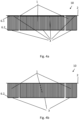
- Fig. 2a shows a filter 10 according to the invention in a first view.
- the filter 10 has three bellows 1 made of pleated filter medium 7, wherein the bellows 1 are flowed through by separate air streams F1, F2 and F3, respectively.
- the bellows 1 have first and second side surfaces 6.1, 6.2. On their first side surfaces 6.1, the bellows 1 are provided with a continuous band 2 and on their second side surfaces 6.2 with a segmented edge band 3. On their first side surfaces 6.1, the bellows 1 can alternatively be provided with a segmented edge band 3, so that three filter elements are present (not shown here, see. Fig. 4a ). Each segment of the segmented edge band 3 is not directly connected to the other segments and extends only to the side surface 6.1, 6.2 of the respective bellows 1.
- the three bellows 1 all have convex outward-curving end folds 5.
- Fig. 2b shows a filter 10 in a second view.
- the three air streams F1, F2, F3 flow through the filter from an inflow side AN to an outflow side AB.
- edges 5.1 of the filter medium 7 of all end folds 5 are all oriented towards one side, here namely the inflow side AN of the filter 10.
- Fig.3 shows a filter arrangement 100 in a roughly schematic sectional view.
- the filter arrangement 100 has a filter 10 as shown in the Fig. 2a and b.
- This filter 10 is accommodated in a filter housing 9.
- the filter 1 can be inserted into the housing 9 in the assembly direction M.
- the filter housing 9 has three compartments 9.1, 9.2, 9.3, which are separated from one another by partition walls.
- Each bellows 1 is assigned a compartment 9.1, 9.2, 9.3.
- the bellows 1 are arranged at a distance from one another and there is a gap 8 between each two bellows 1. Partition walls of a housing 9 can engage in this gap 8.
- the two walls between the compartments 9.1, 9.2, 9.3 engage in the two Column 8.
- the width of column 8 corresponds approximately to the width of the walls and the end folds 5 each rest against the housing 9.
- Fig. 4a shows a variant with three filter elements, which form a filter 10.
- Each filter element has a bellows 1, which is provided with a segmented edge band 3 on its first side surface 6.1 and on its second side surface 6.2.
- the edge band 3 can be glued onto the bellows 1.
- the filter elements are additionally provided with a continuous band 2, which can also be glued on and connects the filter elements to one another.
- Fig. 4b shows a variant with three bellows 1 which form a filter 10.
- Each bellows 1 is provided with a segmented edge band 3 on its second side surface 6.2.
- the edge band 3 can be glued onto the bellows 1.
- the bellows 1 are additionally provided with a continuous band 2, which can also be glued on and connects the bellows 1 to one another.
Landscapes
- Chemical & Material Sciences (AREA)
- Chemical Kinetics & Catalysis (AREA)
- Filtering Of Dispersed Particles In Gases (AREA)
Priority Applications (2)
| Application Number | Priority Date | Filing Date | Title |
|---|---|---|---|
| EP23159688.3A EP4424401B1 (fr) | 2023-03-02 | 2023-03-02 | Ensemble filtre avec filtre à bande de bord segmentée |
| DE102023123890.6A DE102023123890A1 (de) | 2023-03-02 | 2023-09-05 | Filter mit segmentiertem Kantenband und Filteranordnung |
Applications Claiming Priority (1)
| Application Number | Priority Date | Filing Date | Title |
|---|---|---|---|
| EP23159688.3A EP4424401B1 (fr) | 2023-03-02 | 2023-03-02 | Ensemble filtre avec filtre à bande de bord segmentée |
Publications (2)
| Publication Number | Publication Date |
|---|---|
| EP4424401A1 true EP4424401A1 (fr) | 2024-09-04 |
| EP4424401B1 EP4424401B1 (fr) | 2025-10-08 |
Family
ID=85462184
Family Applications (1)
| Application Number | Title | Priority Date | Filing Date |
|---|---|---|---|
| EP23159688.3A Active EP4424401B1 (fr) | 2023-03-02 | 2023-03-02 | Ensemble filtre avec filtre à bande de bord segmentée |
Country Status (2)
| Country | Link |
|---|---|
| EP (1) | EP4424401B1 (fr) |
| DE (1) | DE102023123890A1 (fr) |
Families Citing this family (1)
| Publication number | Priority date | Publication date | Assignee | Title |
|---|---|---|---|---|
| DE102024206186A1 (de) * | 2024-07-02 | 2026-01-08 | BSH Hausgeräte GmbH | Geruchsfiltereinheit für Dunstabzugsvorrichtung |
Citations (10)
| Publication number | Priority date | Publication date | Assignee | Title |
|---|---|---|---|---|
| DE3834942A1 (de) * | 1987-10-14 | 1989-04-27 | Nippon Denso Co | Filtervorrichtung |
| JP2005007361A (ja) * | 2003-06-20 | 2005-01-13 | Denso Corp | エアフィルタ |
| DE102007057616A1 (de) * | 2007-11-30 | 2009-06-04 | Helsa-Automotive Gmbh & Co. Kg | Filtereinsatz und Filtereinrichtung |
| DE102009019859A1 (de) * | 2008-05-07 | 2009-12-03 | Mann + Hummel Gmbh | Filterelement |
| DE102009041113A1 (de) | 2009-09-15 | 2011-03-24 | Carl Freudenberg Kg | Filteranordnung mit einrastbaren V-Laschen |
| DE102015004336A1 (de) * | 2015-04-09 | 2016-10-13 | Mann + Hummel Gmbh | Filterelement mit Lasche und Filtersystem |
| EP3332858A1 (fr) | 2016-12-07 | 2018-06-13 | Carl Freudenberg KG | Élément filtrant |
| DE102017212383A1 (de) * | 2017-07-19 | 2019-01-24 | Mahle International Gmbh | Filterelement für einen Fahrgastinnenraum eines Kraftfahrzeugs |
| DE102019102104A1 (de) | 2019-01-29 | 2020-07-30 | Carl Freudenberg Kg | Filterelement, Filteranordnung mit einem solchen Filterelement und Verwendung der Filteranordnung |
| EP4011480A1 (fr) * | 2020-12-09 | 2022-06-15 | Carl Freudenberg KG | Agencement de filtre pliable comprenant plusieurs éléments filtrants individuels |
-
2023
- 2023-03-02 EP EP23159688.3A patent/EP4424401B1/fr active Active
- 2023-09-05 DE DE102023123890.6A patent/DE102023123890A1/de active Pending
Patent Citations (10)
| Publication number | Priority date | Publication date | Assignee | Title |
|---|---|---|---|---|
| DE3834942A1 (de) * | 1987-10-14 | 1989-04-27 | Nippon Denso Co | Filtervorrichtung |
| JP2005007361A (ja) * | 2003-06-20 | 2005-01-13 | Denso Corp | エアフィルタ |
| DE102007057616A1 (de) * | 2007-11-30 | 2009-06-04 | Helsa-Automotive Gmbh & Co. Kg | Filtereinsatz und Filtereinrichtung |
| DE102009019859A1 (de) * | 2008-05-07 | 2009-12-03 | Mann + Hummel Gmbh | Filterelement |
| DE102009041113A1 (de) | 2009-09-15 | 2011-03-24 | Carl Freudenberg Kg | Filteranordnung mit einrastbaren V-Laschen |
| DE102015004336A1 (de) * | 2015-04-09 | 2016-10-13 | Mann + Hummel Gmbh | Filterelement mit Lasche und Filtersystem |
| EP3332858A1 (fr) | 2016-12-07 | 2018-06-13 | Carl Freudenberg KG | Élément filtrant |
| DE102017212383A1 (de) * | 2017-07-19 | 2019-01-24 | Mahle International Gmbh | Filterelement für einen Fahrgastinnenraum eines Kraftfahrzeugs |
| DE102019102104A1 (de) | 2019-01-29 | 2020-07-30 | Carl Freudenberg Kg | Filterelement, Filteranordnung mit einem solchen Filterelement und Verwendung der Filteranordnung |
| EP4011480A1 (fr) * | 2020-12-09 | 2022-06-15 | Carl Freudenberg KG | Agencement de filtre pliable comprenant plusieurs éléments filtrants individuels |
Also Published As
| Publication number | Publication date |
|---|---|
| EP4424401B1 (fr) | 2025-10-08 |
| DE102023123890A1 (de) | 2023-11-09 |
Similar Documents
| Publication | Publication Date | Title |
|---|---|---|
| DE102009040202B4 (de) | Filter | |
| EP1134014B2 (fr) | Filtre plissé | |
| DE69706551T3 (de) | Filtervorrichtung zum filtrieren eines fluids | |
| EP2135662B2 (fr) | Elément filtrant compressible avec des capuchons d'extrémité inclinés les uns vers les autres | |
| EP2094370B2 (fr) | Module filtrant à élément filtrant compressible, et procédé correspondants | |
| EP1736227B1 (fr) | Système d'étanchéité d'un filtre | |
| EP3680003B1 (fr) | Cartouche filtrante pourvue de buse venturi | |
| EP4424401B1 (fr) | Ensemble filtre avec filtre à bande de bord segmentée | |
| DE102017219009A1 (de) | Filterverbund zum Verbau in einem Fahrzeug | |
| EP3093058A1 (fr) | Élement filtrant pour un dispositif de filtre | |
| EP3077078A1 (fr) | Élément de filtrage avec soufflet de filtrage | |
| DE102014008704B3 (de) | Filter mit einem schräg durchströmten Filterelement | |
| DE102014219403A1 (de) | Filterelement zum Filtern von Fluid mit einem gefalteten Filtermaterial | |
| EP3744414A1 (fr) | Filtre à bande de bord repliée | |
| DE10241748B4 (de) | Filterelement | |
| DE102007035967A1 (de) | Rückspüleinrichtung für eine Filteranlage | |
| DE102024128052A1 (de) | Filterelement und Filtersystem | |
| EP2078554B1 (fr) | Dispositif de filtre destiné à la filtration de fluides gazeux | |
| DE102017000111A1 (de) | Filterelement mit Zusatzbauteil und Filtersystem | |
| DE102015218088A1 (de) | Filtereinrichtung | |
| DE202019104501U1 (de) | Filtereinrichtung für ein Kraftfahrzeug | |
| DE10235122B3 (de) | Flexibler Filter | |
| DE102018202718A1 (de) | Ringdichtung aus elastischem Kunststoff | |
| DE102019102104A1 (de) | Filterelement, Filteranordnung mit einem solchen Filterelement und Verwendung der Filteranordnung | |
| DE102007058616B4 (de) | Filterelement mit einer zickzackförmigen Filterbahn und Filtereinrichtung |
Legal Events
| Date | Code | Title | Description |
|---|---|---|---|
| PUAI | Public reference made under article 153(3) epc to a published international application that has entered the european phase |
Free format text: ORIGINAL CODE: 0009012 |
|
| STAA | Information on the status of an ep patent application or granted ep patent |
Free format text: STATUS: THE APPLICATION HAS BEEN PUBLISHED |
|
| AK | Designated contracting states |
Kind code of ref document: A1 Designated state(s): AL AT BE BG CH CY CZ DE DK EE ES FI FR GB GR HR HU IE IS IT LI LT LU LV MC ME MK MT NL NO PL PT RO RS SE SI SK SM TR |
|
| STAA | Information on the status of an ep patent application or granted ep patent |
Free format text: STATUS: REQUEST FOR EXAMINATION WAS MADE |
|
| 17P | Request for examination filed |
Effective date: 20250227 |
|
| GRAP | Despatch of communication of intention to grant a patent |
Free format text: ORIGINAL CODE: EPIDOSNIGR1 |
|
| STAA | Information on the status of an ep patent application or granted ep patent |
Free format text: STATUS: GRANT OF PATENT IS INTENDED |
|
| RIC1 | Information provided on ipc code assigned before grant |
Ipc: B01D 46/52 20060101ALI20250414BHEP Ipc: B01D 46/58 20220101ALI20250414BHEP Ipc: B01D 46/12 20220101ALI20250414BHEP Ipc: B01D 46/10 20060101ALI20250414BHEP Ipc: B01D 46/00 20220101AFI20250414BHEP |
|
| INTG | Intention to grant announced |
Effective date: 20250507 |
|
| P01 | Opt-out of the competence of the unified patent court (upc) registered |
Free format text: CASE NUMBER: APP_28589/2025 Effective date: 20250616 |
|
| GRAS | Grant fee paid |
Free format text: ORIGINAL CODE: EPIDOSNIGR3 |
|
| GRAA | (expected) grant |
Free format text: ORIGINAL CODE: 0009210 |
|
| STAA | Information on the status of an ep patent application or granted ep patent |
Free format text: STATUS: THE PATENT HAS BEEN GRANTED |
|
| AK | Designated contracting states |
Kind code of ref document: B1 Designated state(s): AL AT BE BG CH CY CZ DE DK EE ES FI FR GB GR HR HU IE IS IT LI LT LU LV MC ME MK MT NL NO PL PT RO RS SE SI SK SM TR |
|
| REG | Reference to a national code |
Ref country code: GB Ref legal event code: FG4D Free format text: NOT ENGLISH Ref country code: CH Ref legal event code: F10 Free format text: ST27 STATUS EVENT CODE: U-0-0-F10-F00 (AS PROVIDED BY THE NATIONAL OFFICE) Effective date: 20251008 |
|
| REG | Reference to a national code |
Ref country code: DE Ref legal event code: R096 Ref document number: 502023001924 Country of ref document: DE |
|
| REG | Reference to a national code |
Ref country code: IE Ref legal event code: FG4D Free format text: LANGUAGE OF EP DOCUMENT: GERMAN |
|
| REG | Reference to a national code |
Ref country code: NL Ref legal event code: MP Effective date: 20251008 |
|
| PG25 | Lapsed in a contracting state [announced via postgrant information from national office to epo] |
Ref country code: NL Free format text: LAPSE BECAUSE OF FAILURE TO SUBMIT A TRANSLATION OF THE DESCRIPTION OR TO PAY THE FEE WITHIN THE PRESCRIBED TIME-LIMIT Effective date: 20251008 |
|
| PG25 | Lapsed in a contracting state [announced via postgrant information from national office to epo] |
Ref country code: ES Free format text: LAPSE BECAUSE OF FAILURE TO SUBMIT A TRANSLATION OF THE DESCRIPTION OR TO PAY THE FEE WITHIN THE PRESCRIBED TIME-LIMIT Effective date: 20251008 |
|
| REG | Reference to a national code |
Ref country code: LT Ref legal event code: MG9D |
|
| PG25 | Lapsed in a contracting state [announced via postgrant information from national office to epo] |
Ref country code: NO Free format text: LAPSE BECAUSE OF FAILURE TO SUBMIT A TRANSLATION OF THE DESCRIPTION OR TO PAY THE FEE WITHIN THE PRESCRIBED TIME-LIMIT Effective date: 20260108 |
|
| PGFP | Annual fee paid to national office [announced via postgrant information from national office to epo] |
Ref country code: DE Payment date: 20260320 Year of fee payment: 4 |
|
| PG25 | Lapsed in a contracting state [announced via postgrant information from national office to epo] |
Ref country code: HR Free format text: LAPSE BECAUSE OF FAILURE TO SUBMIT A TRANSLATION OF THE DESCRIPTION OR TO PAY THE FEE WITHIN THE PRESCRIBED TIME-LIMIT Effective date: 20251008 Ref country code: FI Free format text: LAPSE BECAUSE OF FAILURE TO SUBMIT A TRANSLATION OF THE DESCRIPTION OR TO PAY THE FEE WITHIN THE PRESCRIBED TIME-LIMIT Effective date: 20251008 |
|
| PGFP | Annual fee paid to national office [announced via postgrant information from national office to epo] |
Ref country code: AT Payment date: 20260301 Year of fee payment: 4 |
|
| PG25 | Lapsed in a contracting state [announced via postgrant information from national office to epo] |
Ref country code: RS Free format text: LAPSE BECAUSE OF FAILURE TO SUBMIT A TRANSLATION OF THE DESCRIPTION OR TO PAY THE FEE WITHIN THE PRESCRIBED TIME-LIMIT Effective date: 20260108 |
|
| PG25 | Lapsed in a contracting state [announced via postgrant information from national office to epo] |
Ref country code: IS Free format text: LAPSE BECAUSE OF FAILURE TO SUBMIT A TRANSLATION OF THE DESCRIPTION OR TO PAY THE FEE WITHIN THE PRESCRIBED TIME-LIMIT Effective date: 20260208 |