EP4431985B1 - Suivi d'objet sécurisé d'un objet - Google Patents
Suivi d'objet sécurisé d'un objet Download PDFInfo
- Publication number
- EP4431985B1 EP4431985B1 EP23162021.2A EP23162021A EP4431985B1 EP 4431985 B1 EP4431985 B1 EP 4431985B1 EP 23162021 A EP23162021 A EP 23162021A EP 4431985 B1 EP4431985 B1 EP 4431985B1
- Authority
- EP
- European Patent Office
- Prior art keywords
- protective
- safe
- fields
- partial
- safe output
- Prior art date
- Legal status (The legal status is an assumption and is not a legal conclusion. Google has not performed a legal analysis and makes no representation as to the accuracy of the status listed.)
- Active
Links
Images


Classifications
-
- H—ELECTRICITY
- H04—ELECTRIC COMMUNICATION TECHNIQUE
- H04N—PICTORIAL COMMUNICATION, e.g. TELEVISION
- H04N13/00—Stereoscopic video systems; Multi-view video systems; Details thereof
- H04N13/20—Image signal generators
- H04N13/204—Image signal generators using stereoscopic image cameras
-
- G—PHYSICS
- G01—MEASURING; TESTING
- G01S—RADIO DIRECTION-FINDING; RADIO NAVIGATION; DETERMINING DISTANCE OR VELOCITY BY USE OF RADIO WAVES; LOCATING OR PRESENCE-DETECTING BY USE OF THE REFLECTION OR RERADIATION OF RADIO WAVES; ANALOGOUS ARRANGEMENTS USING OTHER WAVES
- G01S17/00—Systems using the reflection or reradiation of electromagnetic waves other than radio waves, e.g. lidar systems
- G01S17/02—Systems using the reflection of electromagnetic waves other than radio waves
- G01S17/04—Systems determining the presence of a target
-
- F—MECHANICAL ENGINEERING; LIGHTING; HEATING; WEAPONS; BLASTING
- F16—ENGINEERING ELEMENTS AND UNITS; GENERAL MEASURES FOR PRODUCING AND MAINTAINING EFFECTIVE FUNCTIONING OF MACHINES OR INSTALLATIONS; THERMAL INSULATION IN GENERAL
- F16P—SAFETY DEVICES IN GENERAL; SAFETY DEVICES FOR PRESSES
- F16P3/00—Safety devices acting in conjunction with the control or operation of a machine; Control arrangements requiring the simultaneous use of two or more parts of the body
- F16P3/12—Safety devices acting in conjunction with the control or operation of a machine; Control arrangements requiring the simultaneous use of two or more parts of the body with means, e.g. feelers, which in case of the presence of a body part of a person in or near the danger zone influence the control or operation of the machine
- F16P3/14—Safety devices acting in conjunction with the control or operation of a machine; Control arrangements requiring the simultaneous use of two or more parts of the body with means, e.g. feelers, which in case of the presence of a body part of a person in or near the danger zone influence the control or operation of the machine the means being photocells or other devices sensitive without mechanical contact
- F16P3/142—Safety devices acting in conjunction with the control or operation of a machine; Control arrangements requiring the simultaneous use of two or more parts of the body with means, e.g. feelers, which in case of the presence of a body part of a person in or near the danger zone influence the control or operation of the machine the means being photocells or other devices sensitive without mechanical contact using image capturing devices
-
- F—MECHANICAL ENGINEERING; LIGHTING; HEATING; WEAPONS; BLASTING
- F16—ENGINEERING ELEMENTS AND UNITS; GENERAL MEASURES FOR PRODUCING AND MAINTAINING EFFECTIVE FUNCTIONING OF MACHINES OR INSTALLATIONS; THERMAL INSULATION IN GENERAL
- F16P—SAFETY DEVICES IN GENERAL; SAFETY DEVICES FOR PRESSES
- F16P3/00—Safety devices acting in conjunction with the control or operation of a machine; Control arrangements requiring the simultaneous use of two or more parts of the body
- F16P3/12—Safety devices acting in conjunction with the control or operation of a machine; Control arrangements requiring the simultaneous use of two or more parts of the body with means, e.g. feelers, which in case of the presence of a body part of a person in or near the danger zone influence the control or operation of the machine
- F16P3/14—Safety devices acting in conjunction with the control or operation of a machine; Control arrangements requiring the simultaneous use of two or more parts of the body with means, e.g. feelers, which in case of the presence of a body part of a person in or near the danger zone influence the control or operation of the machine the means being photocells or other devices sensitive without mechanical contact
- F16P3/144—Safety devices acting in conjunction with the control or operation of a machine; Control arrangements requiring the simultaneous use of two or more parts of the body with means, e.g. feelers, which in case of the presence of a body part of a person in or near the danger zone influence the control or operation of the machine the means being photocells or other devices sensitive without mechanical contact using light grids
-
- G—PHYSICS
- G01—MEASURING; TESTING
- G01S—RADIO DIRECTION-FINDING; RADIO NAVIGATION; DETERMINING DISTANCE OR VELOCITY BY USE OF RADIO WAVES; LOCATING OR PRESENCE-DETECTING BY USE OF THE REFLECTION OR RERADIATION OF RADIO WAVES; ANALOGOUS ARRANGEMENTS USING OTHER WAVES
- G01S17/00—Systems using the reflection or reradiation of electromagnetic waves other than radio waves, e.g. lidar systems
- G01S17/02—Systems using the reflection of electromagnetic waves other than radio waves
- G01S17/06—Systems determining position data of a target
- G01S17/42—Simultaneous measurement of distance and other co-ordinates
-
- G—PHYSICS
- G01—MEASURING; TESTING
- G01S—RADIO DIRECTION-FINDING; RADIO NAVIGATION; DETERMINING DISTANCE OR VELOCITY BY USE OF RADIO WAVES; LOCATING OR PRESENCE-DETECTING BY USE OF THE REFLECTION OR RERADIATION OF RADIO WAVES; ANALOGOUS ARRANGEMENTS USING OTHER WAVES
- G01S17/00—Systems using the reflection or reradiation of electromagnetic waves other than radio waves, e.g. lidar systems
- G01S17/66—Tracking systems using electromagnetic waves other than radio waves
-
- G—PHYSICS
- G01—MEASURING; TESTING
- G01S—RADIO DIRECTION-FINDING; RADIO NAVIGATION; DETERMINING DISTANCE OR VELOCITY BY USE OF RADIO WAVES; LOCATING OR PRESENCE-DETECTING BY USE OF THE REFLECTION OR RERADIATION OF RADIO WAVES; ANALOGOUS ARRANGEMENTS USING OTHER WAVES
- G01S17/00—Systems using the reflection or reradiation of electromagnetic waves other than radio waves, e.g. lidar systems
- G01S17/88—Lidar systems specially adapted for specific applications
- G01S17/89—Lidar systems specially adapted for specific applications for mapping or imaging
- G01S17/894—Three-dimensional [3D] imaging with simultaneous measurement of time-of-flight at a two-dimensional [2D] array of receiver pixels, e.g. time-of-flight cameras or flash lidar
-
- G—PHYSICS
- G01—MEASURING; TESTING
- G01S—RADIO DIRECTION-FINDING; RADIO NAVIGATION; DETERMINING DISTANCE OR VELOCITY BY USE OF RADIO WAVES; LOCATING OR PRESENCE-DETECTING BY USE OF THE REFLECTION OR RERADIATION OF RADIO WAVES; ANALOGOUS ARRANGEMENTS USING OTHER WAVES
- G01S7/00—Details of systems according to groups G01S13/00, G01S15/00, G01S17/00
- G01S7/48—Details of systems according to groups G01S13/00, G01S15/00, G01S17/00 of systems according to group G01S17/00
- G01S7/497—Means for monitoring or calibrating
-
- G—PHYSICS
- G01—MEASURING; TESTING
- G01V—GEOPHYSICS; GRAVITATIONAL MEASUREMENTS; DETECTING MASSES OR OBJECTS; TAGS
- G01V8/00—Prospecting or detecting by optical means
- G01V8/10—Detecting, e.g. by using light barriers
- G01V8/12—Detecting, e.g. by using light barriers using one transmitter and one receiver
-
- G—PHYSICS
- G01—MEASURING; TESTING
- G01V—GEOPHYSICS; GRAVITATIONAL MEASUREMENTS; DETECTING MASSES OR OBJECTS; TAGS
- G01V8/00—Prospecting or detecting by optical means
- G01V8/10—Detecting, e.g. by using light barriers
- G01V8/20—Detecting, e.g. by using light barriers using multiple transmitters or receivers
-
- G—PHYSICS
- G05—CONTROLLING; REGULATING
- G05B—CONTROL OR REGULATING SYSTEMS IN GENERAL; FUNCTIONAL ELEMENTS OF SUCH SYSTEMS; MONITORING OR TESTING ARRANGEMENTS FOR SUCH SYSTEMS OR ELEMENTS
- G05B19/00—Program-control systems
- G05B19/02—Program-control systems electric
- G05B19/18—Numerical control [NC], i.e. automatically operating machines, in particular machine tools, e.g. in a manufacturing environment, so as to execute positioning, movement or co-ordinated operations by means of program data in numerical form
- G05B19/406—Numerical control [NC], i.e. automatically operating machines, in particular machine tools, e.g. in a manufacturing environment, so as to execute positioning, movement or co-ordinated operations by means of program data in numerical form characterised by monitoring or safety
-
- H—ELECTRICITY
- H04—ELECTRIC COMMUNICATION TECHNIQUE
- H04N—PICTORIAL COMMUNICATION, e.g. TELEVISION
- H04N13/00—Stereoscopic video systems; Multi-view video systems; Details thereof
- H04N13/20—Image signal generators
- H04N13/271—Image signal generators wherein the generated image signals comprise depth maps or disparity maps
-
- G—PHYSICS
- G05—CONTROLLING; REGULATING
- G05B—CONTROL OR REGULATING SYSTEMS IN GENERAL; FUNCTIONAL ELEMENTS OF SUCH SYSTEMS; MONITORING OR TESTING ARRANGEMENTS FOR SUCH SYSTEMS OR ELEMENTS
- G05B2219/00—Program-control systems
- G05B2219/30—Nc systems
- G05B2219/50—Machine tool, machine tool null till machine tool work handling
- G05B2219/50193—Safety in general
Definitions
- the invention relates to a monitoring device and a method for secure object tracking of an object according to the preamble of claims 1 and 15 respectively.
- Optoelectronic sensors are very often used in contactless monitoring to protect against hazards, such as machines in industrial environments or vehicles in logistics applications.
- a laser scanner and a camera, and in particular a 3D camera are particularly useful.
- a light beam generated by a laser periodically sweeps over a monitoring area with the help of a deflection unit.
- the light is remitted by objects in the monitoring area and evaluated in the laser scanner.
- the angular position of the deflection unit is used to determine the angular position of the object, and the light travel time, using the speed of light, is used to determine the distance of the object from the laser scanner.
- the angle and distance information is used to record the location of an object in the monitoring area in two-dimensional polar coordinates.
- the third spatial coordinate can also be recorded by a relative movement in the transverse direction, for example by a further degree of freedom of movement of the deflection unit in the laser scanner or by moving the object relative to the laser scanner.
- a 3D camera measures a distance and thereby obtains depth information.
- the captured three-dimensional image data with distance or range values for the individual pixels is also called a 3D image, range image or depth map.
- 3D cameras are available in various technologies, including time-of-flight, stereoscopic and projection methods, or plenoptic cameras.
- TOF time-of-flight camera
- a scene is illuminated with amplitude-modulated light.
- the light returning from the scene is received and demodulated at the same frequency that is used to modulate the transmitted light (lock-in method).
- the demodulation results in an amplitude measurement value that corresponds to a sample value of the received signal.
- the Nyquist criterion at least two samples are necessary to determine the phase of a periodic signal.
- the measurement is therefore carried out with different relative phase positions between the signals for the transmit-side modulation and the receive-side demodulation. This can then be used to determine the absolute phase shift between the transmitted and received signals due to the time of flight, which in turn is proportional to the object distance in the scene.
- a protective field is monitored that the operating personnel must not enter while the machine is in operation. If the sensor detects an inadmissible intrusion into the protective field, such as an operator's leg, the machine is put into a safe state.
- Sensors used in safety technology must work particularly reliably and therefore meet high safety requirements, for example the EN13849 standard for machine safety and the EN61496 device standard for non-contact protective devices (ESPD). A number of measures must be taken to meet these safety standards, such as secure electronic evaluation using redundant, diverse electronics or various function monitoring, especially monitoring the contamination of optical components including a front screen.
- a safety laser scanner or a safety camera that meets these standards and is designed for protective field evaluation works internally with very large amounts of information from the scan point clouds or depth maps. However, only highly compressed binary information is made available to the outside, namely whether the protective field is violated or not.
- a secure output is usually used for this (OSSD, Output Signal Switching Device). More complex secure evaluations such as determining the position of an object or object tracking are not conventionally available.
- Algorithms for object tracking with optical detection have long been available, based on classic image processing, Kalman filters or, increasingly, artificial intelligence. However, this is not suitable for safety-related use due to the complexity and lack of suitable sensors and control components. Even if it were possible to harden an algorithm using appropriate security measures so that it would meet safety standards, the scan or image data required for this cannot be accessed securely in a safety laser scanner or a safety camera. As already described, there is only one external interface for one bit of secure information about a protective field violation. The internal computing resources of the sensor or those of a safety controller are also far from sufficient to implement object tracking using one of the known procedures.
- the EP 3 470 879 A1 configures at least partially overlapping monitoring fields in a laser scanner. This creates monitoring segments that differ from one another in terms of which monitoring fields overlap there. The number of monitoring fields provided by the hardware is thus refined to the monitoring segments. With clever configuration, n monitoring fields can be turned into 2 n or even slightly more monitoring segments. However, this still does not achieve a particularly fine resolution as long as n is limited to very small values on the hardware side, and for larger n the configuration effort would very quickly become prohibitive.
- the EP 3 709 106 A1 proposes a safety system that validates complex non-safe evaluations with less complex safe evaluations.
- objects are located in a non-safe manner using scan point clouds.
- the scan point cloud of a safety laser scanner cannot actually be read out in reality, and there is no non-safe interface for this purpose, so new devices are required.
- a safe position in the narrower sense is limited to the grid of protective fields, which must remain coarse due to the small number of possible protective fields.
- a parking aid that illuminates the rear area with Fresnel rings and uses a receiver to determine the light level. If the Fresnel rings pass over an object while the vehicle is moving, the light level increases or decreases depending on whether a light or dark zone is currently hitting the object. By counting the light-dark transitions, the relative position of the object to the vehicle can be determined. In another embodiment, alternating Fresnel rings are generated using two light transmitters with different wavelengths and their transitions are evaluated.
- rotary encoders or incremental encoders are known that are made up of two parts that move relative to each other.
- a scanning unit is connected to one part and a measuring element to the second part.
- the measuring element has code tracks and the scanning unit generates scanning signals by scanning the code tracks.
- the scanning signals can be used to determine the respective position of the two parts relative to each other.
- the monitoring device has at least one first secure optoelectronic sensor and a safety control connected to it.
- Safety control means a secure evaluation unit that can be implemented in any hardware. is, in particular, a safety controller as a controller approved for safety applications in the narrower sense.
- safe and security mean that measures have been taken to control errors up to a specified safety level or to comply with the provisions of a relevant safety standard for machine safety or non-contact protective devices, some of which are mentioned in the introduction. However, this does not necessarily mean that the monitoring device is used in a safety application, even if it could.
- the first safe optoelectronic sensor comprises a light receiver that generates a reception signal from received light from the monitoring area.
- the reception signal is, for example, the signal from a photodiode that receives a returning scanning beam, or image data from an image sensor is generally referred to as a reception signal.
- the first sensor also has at least two safe outputs, in particular OSSDs, at each of which a preferably binary safe output signal can be output.
- the two safe outputs are preferably separate physical connections, but can also be implemented as a bit or the like of a more complex safe output.
- a first control and evaluation unit of the first sensor is designed for protective field monitoring with at least two protective fields, a first protective field or protective field A and a second protective field or protective field B.
- the protective fields are each individually configurable sub-areas of the monitoring area and bear the historical name protective field, although in reality, depending on the first sensor, it can be a three-dimensional spatial area.
- An object entering the first protective field leads to a safe output signal at the first safe output and, correspondingly, in the second protective field to a safe output signal at the second safe output.
- the affiliation is sometimes expressed below by referring to the safe outputs as OSSD A and OSSD B, for example.
- OSSD A and B are preferably in the On state when there is an object in the associated protective field A or B and otherwise in the Off state.
- the safety controller is designed to evaluate the safe output signals.
- the invention is based on the basic idea of dividing the two protection fields into separate partial protection fields and thus obtaining a finer spatial resolution. This initially only applies to one dimension, but can be expanded to two and, if necessary, three dimensions in embodiments to be described.
- the first and second protection fields are each configured as several partial protection fields, and the partial protection fields are lined up along a first line in such a way that the partial protection fields are interlocked, so to speak, i.e. first partial protection fields of the first protection field alternate with second partial protection fields of the second protection field. There may or may not be gaps and/or an overlap.
- the sequence is preferably alternating, i.e. if the first line is followed, the two protection fields are violated according to the ..ABABABA.. pattern.
- the protection fields form a type of code track, and more complex code patterns are conceivable, with ..ABBABAAB.. being just one of countless other examples. It is also conceivable to add at least one further protection field C, D ... and thus form more powerful codes. All of this is known per se, for example from rotary encoders, and is therefore not described in detail here, but using the simple representative example ..ABABABA..
- the first line can be curved or preferably straight; according to the invention, a partial protection field corresponds to a discrete coordinate along the line, whereby the grain can be somewhat finer by switching protection fields, as explained later.
- protective fields can be freely configured, each with in principle any number of partial protective fields of any shape, separated from one another and of any size within the resolution of the first sensor.
- partial protective fields of the same protective field are dependent on one another. An infringement is only reported together at the corresponding safe output, so the first sensor initially does not provide any information as to which partial protective field of the affected protective field an object intrusion has occurred in.
- the invention makes it possible to find this out through the special configuration of the at least two protective fields.
- the invention has the advantage that discrete, safe object tracking can be implemented in one direction of movement, and later also in several directions of movement with significantly increased resolution, which is not closely tied to the extremely small number of simultaneously monitored protective fields, but manages with two protective fields per direction of movement.
- This makes use of the high degree of design freedom when configuring the geometry of a protective field.
- This opens up a new safety function. It is based on the already safe protective field evaluation and the equally safe outputs and thus inherits the functional safety to a certain extent without any additional effort.
- the safe, discrete object tracking can be used as a plausibility check or validation of an even finer, non-safe object tracking function, for example with the concept of the introductory discussion. EP 3 709106 A1 . Thanks to the invention, the grid for validation becomes much finer, so that remaining possible errors of the non-secure object tracking function receive a significantly lower upper bound.
- the safety controller is preferably designed to evaluate a temporal sequence of the safe output signals at the first safe output and the second safe output in order to determine a position of the object along the first line. From the temporal sequence it is possible to determine which of the partial protection fields is violated, and this results in a position in the resolution of the partial protection fields, not just the protection fields.
- the first partial protection fields form a first code track and the second partial protection fields form a second code track.
- the partial protection fields and the gaps between them code for one and zero, and the scanning of this special code track takes place when a moving object enters and leaves a partial protection field and the associated safe output changes its state accordingly.
- the first partial protection fields and the second partial protection fields partially overlap one another in the direction of the first line, in particular by half.
- a free area without a partial protection field is arranged along the first line between the partial protection fields.
- the overlap and free area are particularly preferably cumulated, with an injury sequence ..A AB B (empty) A AB ..
- the free area can be as large as a partial protection field and/or their mutual overlap.
- Another preferred extent of the free area is measured by whether a person can fit in it without triggering a protection field, and this results in a size of 50 cm - 1 m, in particular 60 cm, corresponding to the horizontal extent of a standing person.
- the overlap area can be as large as the free area, but the actual requirement here is that both overlapping protective fields are reliably triggered when the overlap area is entered. A smaller extension of, for example, 20 cm is sufficient for this.
- the safety controller is preferably designed to determine the temporal sequence of the safe output signals using an incremental encoder method for the evaluation to evaluate the scanning signals of two code tracks of a measuring embodiment that are offset from one another.
- the analogy to an incremental encoder is not just an illustration; the safe output signals have the same course as the scanning signals of an incremental encoder. This means that the entire powerful arsenal of coding and evaluation is available that was developed for incremental encoders, is therefore known per se, and can be used according to the invention without explaining it in detail here.
- the safety controller is preferably designed to determine the direction of the object's movement from the chronological sequence of the safe output signals. This works particularly reliably with the arrangement of partial protection fields with mutual overlap and free space specified above. If the safe output signals show .. A AB B (empty)..., the object has moved forwards, and if B AB A it has moved backwards.
- the safety controller preferably has a counter that is counted up and down according to the direction of movement when entering and leaving a partial protection field. If the respective direction is known, the position can be recorded incrementally with a counter. It is conceivable to record interventions in a specific protection field in separate counters, but a single counter that does not differentiate which protection field is affected is also sufficient. This could be calculated back from the counter reading anyway. The real position on the first line can be calculated from the counter reading with knowledge of the protection field geometry.
- the safety controller is preferably designed to only process a safe output signal at one of the safe outputs as a new safe output signal if a safe output signal is present at the other safe output in the meantime.
- Incremental encoders tend to bounce. The term originally comes from a switch or button that triggers several times in quick succession due to a malfunction. Something similar can happen if an object is located at the boundary of a protective field. The measure mentioned serves to debounce. A largely stationary object at the boundary of the protective field only triggers another violation of the same protective field when it bounces, while a moving object inevitably violates the other protective field.
- the partial protection fields preferably have the same shape and/or size. This results in uniform code elements, which make both configuration and evaluation much easier and significantly reduce their susceptibility to errors.
- the partial protection fields preferably have a simple shape, for example rectangular or cuboid. This requirement is not necessary for the functional principle.
- the safety controller is preferably designed to move the protective fields along the first line as soon as a safe output signal is present at one of the safe outputs.
- the partial protective fields track the object, which repeatedly breaks through the moved protective field boundary during its movement.
- the movement preferably takes place by a fraction of the distance between two partial protective fields.
- a configuration with equally large partial protective fields and distances corresponding to the extent of the partial protective fields ..A(empty)B(empty)... is preferably provided.
- the movement preferably takes place by switching to a staggered arrangement of the protective fields.
- the preferred configuration mentioned can be achieved with four switchable protective field sets.
- the movements are preferably counted in order to determine the position incrementally.
- the safety controller is preferably designed to move the protective fields in one direction when there is a safe output signal at the first safe output and in the other direction when there is a safe output signal at the second safe output.
- the first protective field is then used to detect forward movement and the second protective field is used to detect backward movement along the first line.
- a counter is counted up or down depending on the direction of movement.
- the first safe optoelectronic sensor is preferably a 3D camera, in particular a time-of-flight camera. This makes it possible to capture a large monitoring area and to configure protective fields and partial protective fields in a fine grid.
- the 3D camera which was originally only designed for protective field evaluation, is given the additional function of safe object tracking by the invention.
- the first safe optoelectronic sensor can alternatively be a laser scanner, but this requires a suitable perspective.
- the safety controller is preferably designed to trigger a safeguard for a machine monitored by the monitoring device if the object is in a dangerous position and/or in a dangerous movement.
- the assessment of whether an object position or movement is dangerous can be carried out in a downstream processing unit, which is here, for the sake of simplicity, assigned to the safety controller.
- a dangerous position can be too close to a machine or a machine part, with possible time dependencies or taking into account the machine's work processes. Movements enable additional assessments, because, for example, a movement parallel to the machine or even with a subcomponent away from it is less critical than moving directly towards the machine.
- Speed can also play a role (speed and separation monitoring).
- the safeguard can consist of swerving, slowing down or stopping the machine or assuming another safe state.
- the monitoring device preferably has a second optoelectronic sensor with a second light receiver, at least one third safe output and one fourth safe output, and a second control and evaluation unit, which is designed for protective field monitoring of at least one third protective field with several third partial protective fields and a fourth protective field with several fourth partial protective fields with output of a safe output signal at the third safe output or the fourth safe output in the event of object intervention, wherein the third partial protective fields and fourth partial protective fields are arranged alternatingly one after the other along a second line transverse to the first line and wherein in particular the safety control is designed to evaluate a temporal sequence of the safe output signals at the third safe output and the fourth safe output in order to determine a position of the object along the second line.
- the second optoelectronic sensor is therefore also able to divide two protective fields into partial protective fields and to monitor them and provide corresponding safe output signals. It therefore corresponds to the first optoelectronic sensor, at least with regard to the features essential to the invention, and is preferably functionally or even structurally identical.
- the two sensors monitor partial protection fields that are lined up on lines oriented transversely to each other. This enables object tracking in two dimensions.
- the second line like the first line, is preferably straight and even more preferably oriented perpendicular to the first line. This then results in Cartesian coordinates. At least one line can be curved, which then results in distorted coordinates result, which can be transformed into Cartesian coordinates at any time if the protective field geometry is known.
- the first control and evaluation unit is preferably designed to switch the protective field monitoring to a third protective field with several third partial protective fields and a fourth protective field with several fourth partial protective fields, wherein the third partial protective fields and fourth partial protective fields are arranged alternatingly one after the other along a second line transverse to the first line, and wherein in particular the safety controller is designed to evaluate a temporal sequence of the safe output signals in order to determine a position of the object along the second line. Violations of the third and fourth protective fields preferably lead to a corresponding safe output signal at the first or second safe output.
- the switching preferably takes place very quickly (toggling) and in particular faster than a response time of the protective fields required by the safety concept, so that effectively all protective fields are monitored simultaneously. This is an alternative to the embodiment of the previous paragraph, which emulates the second safe optoelectronic sensor by switching, so that only one sensor is required.
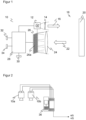
- FIG. 1 shows a schematic block diagram of a camera 10, which is preferably designed as a 3D time-of-flight camera and which is described as representative of an optoelectronic sensor that can be used in connection with the invention.
- An illumination unit 12 emits transmitted light 16 modulated by a transmitting optics 14 into a monitoring area 18. LEDs or lasers in the form of edge emitters or VCSELs can be considered as the light source.
- the illumination unit 12 can be controlled in such a way that the amplitude of the transmitted light 16 is modulated with a frequency typically in the range of 1 MHz to 1000 MHz.
- the modulation is, for example, sinusoidal or rectangular, in any case a periodic modulation.
- the frequency creates a limited unambiguous range of the distance measurement, so that small modulation frequencies are required for large ranges of the camera 10.
- measurements are carried out at two to three or more modulation frequencies in order to increase the unambiguous range by combining the measurements.
- the transmitted light 16 hits an object or a person 20 in the monitoring area 18, a part is reflected back to the camera 10 as received light 22 and there through a receiving optics 24, for example a single lens or a receiving lens, to an image sensor 26.
- the image sensor 26 has a large number of receiving elements or receiving pixels 26a, for example arranged in a matrix or row.
- the resolution of the image sensor 26 can range from two or a few to thousands or millions of receiving pixels 26a.
- Demodulation takes place in this in accordance with a lock-in method.
- the pixel arrangement is typically a matrix, so that a lateral spatial resolution is obtained in an X direction and a Y direction, which is complemented by the Z direction of the distance measurement to the three-dimensional image data.
- This 3D capture is preferably what is meant when we talk about a 3D camera, a 3D time-of-flight camera or three-dimensional image data.
- other pixel arrangements are also conceivable, such as a pixel row that is selected in a matrix or that forms the entire image sensor of a line camera.
- At least two protective fields are configured in a control and evaluation unit 28 with at least one digital computing component such as a microprocessor or the like. These are geometric specifications for a sub-area of the monitoring area 18, which are configured, for example, in a CAD program or in any other way using the control and evaluation unit 28 or imported via an interface 30.
- the protective fields are monitored for object intrusions, and if a protective field is violated, a safe output signal is output at a safe output 32, 34 assigned to the protective field. The state of the safe output therefore reflects in binary form the presence or absence of an object in the associated protective field.
- the two protective fields are referred to below as protective field A and B, and the associated safe output 32, 34 as OSSD A and OSSD B.
- the camera 10 and in particular the protective field evaluation including the output signals or OSSD states are safe in the sense defined in the introduction.
- FIG. 2 shows a schematic representation of a monitoring device with two cameras 10a-b and a safety controller 36, which can be used, for example, at an intersection or in connection with the control of a robot.
- a safety controller 36 which can be used, for example, at an intersection or in connection with the control of a robot.
- only one camera is provided, although other optoelectronic sensors are also possible, in particular a laser scanner.
- a safety controller 36 which is initially to be understood generally as a safe evaluation of a computing unit in any hardware and only preferably as a safety controller in the narrower sense.
- the safety controller 36 carries out safe object tracking, the result of which is, for example, safe values for the position and, if necessary, speed at a particular point in time. This in turn can be used for a risk assessment in a higher-level evaluation (not shown), which is alternatively also implemented in the safety controller 36. If a danger is detected, a safety-related signal is sent to a monitored machine or robot. The machine or robot then slows down or switches to work steps that cannot pose a risk, at least with this detected object movement, and the machine is only transferred to a safe state if absolutely necessary. This achieves a high level of availability and productivity overall.
- Safe object tracking is an important basic function for a wide range of automation applications in manufacturing and logistics, for example when a vehicle has to avoid a person and not just stop. Likewise, robots should use knowledge of the exact position of a person nearby to switch to other work areas and maintain productive processes. Future security solutions that influence automatic processes in a larger area, up to an entire hall or factory, at a higher level also depend on knowledge of the positions of all people.
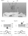
- Figure 3 shows an example depth map with two protection fields. According to a recording perspective from above, parts of the floor and the upper part of the body of a person 20 are recorded as a 3D point cloud. Two overlapping protection fields 38A-B are configured at head height.
- Figure 4a shows in the upper part an alternative representation of the protective fields 38A-B from a top view and in the lower part a temporal signal curve at the associated safe outputs 32, 34, which are designated OSSD A and OSSD B, during a movement of the person 20 through the protective fields 38A-B, hereinafter referred to as protective fields A and B.
- Figure 4b This is shown when person 20 moves in the opposite direction.
- the protective fields A and B can be understood as code elements of a code track of an incremental encoder.
- An incremental encoder is used to measure a linear movement or to measure a rotary movement in discrete steps. To do this, it uses at least two separate code tracks with incremental code elements, each of which generates a binary periodic signal when moving. The signals from both code tracks are phase-shifted to one another, which makes it possible to determine the direction of movement. The principle can be transferred to discrete object tracking with an optical sensor and protective field monitoring.
- the scanning of a respective code element generates a pulse in the scanning signal.
- the movement of the person 20 through a protective field A or B generates a temporary on state on the associated OSSD A or B, which is also pulse-shaped.
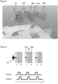
- Figure 5 shows an example depth map similar Figure 3 now with several partial protection fields. This takes advantage of the fact that the protective fields 38A-B can be configured almost as desired. In terms of protective field evaluation, there are still only the two protective fields A and B. However, each of the protective fields A and B is now divided into a large number of non-connected partial protection fields, with the partial protection fields being lined up alternately along a line. This enables object or movement tracking along the line and thus in one dimension. In a further embodiment, which will be described later with reference to the Figure 7 This can be extended to two or three dimensions.
- Figure 6 shows in the upper part the protection fields A and B divided into partial protection fields of the Figure 5 again from the top view and in the lower part a signal curve at OSSD A and OSSD B, while a person 20 moves in the indicated direction through the protective fields.
- the periodic continuation of the constellation of the Figures 3, 4a-b expands individual code elements to form a code track.
- Person 20 generates a sequence of pulse pairs by moving through the protective fields A and B and their partial protective fields.
- Such a signal path corresponds to the scanning signals of an incremental encoder.
- Figure 4a-b explains how each pair of pulses can be evaluated to reliably determine the direction of movement.
- the linear movement of person 20 can be measured using a counter and the partial protection fields.
- the counter is counted up, and if there is movement in the opposite direction, it is counted down.
- the counter value can be converted into a discrete linear position using the specific protection field geometry. Initializing the counter is not a problem as long as people 20 can only enter the area of protection fields A and B from either the left or the right, and the direction of movement can also be used to differentiate between right and left.
- structural or other measures may be required to prevent a person 20 from entering from the side. In the later two-dimensional extension, this is also not necessary because a person 20 does not appear in the middle of a room. All that is required here is a protocol when activating and releasing the system so that initially no person 20 is in or between the protection fields, but these are common measures in safety technology.
- the protective field evaluation and the signals on the OSSDs are reliable in terms of functional safety, only the simple binary counter evaluation must be implemented in accordance with the specifications of functional safety.
- a safety controller 36 with very moderate performance is sufficient for this.
- the resulting counter reading can be evaluated using internal logic operations and in turn used as a control signal for a machine. This can be used to prompt a machine or a robot in particular to take suitable measures that exclude a hazard, up to and including complete braking or shutdown.
- the secure position information or object tracking can also be evaluated in a much more complex way, for example by making the appropriate safety measure dependent on the trajectories, possibly also speeds and accelerations, of monitored persons or the machine status.
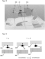
- Figure 7 shows a schematic representation of two pairs of protective fields 38Ax, 38Bx, 38Ay, 38By arranged in a crossed manner for object tracking, now in two dimensions.
- the respective width is preferably adjusted so that the flat area is covered by the resulting grid of partial protective fields.
- the movement tracking takes place as described.
- two counters one per direction or dimension, have to track the positions along their respective direction by counting up or down.
- the orientation of the two protective field pairs 38Ax, 38Bx, 38Ay, 38By is preferably perpendicular to each other, but slanted coordinates can be treated in a completely analogous manner if the protective field geometry is known. This also applies to curved partial protective fields or curved lines along which they are lined up; then a corresponding coordinate transformation into Cartesian coordinates is possible if the protective field geometry is known.
- Figure 8 shows an exemplary depth map with a person 20 and protective fields 38A-B to explain a further embodiment.
- the protective fields 38A-B are switched synchronously with the movement.
- Figure 9 shows the protective fields 38A-B of the Figure 8 again in a top view in three different stages of a movement. Only two partial protection fields are shown, this will be explained later with Figure 10 Analogous to the previous procedure, the periodic use of a large number of such partial protection fields will be continued.
- the protective field 38A for the forward movement is violated again, the counter is incremented to n+2 and switched once again to a protective field set that is slightly offset upwards. If there is a respective backward movement, a correspondingly reversed protective field switch takes place with a protective field set that is offset downwards and the counter for the position is decremented by one.
- Figure 10 shows a schematic representation of four protective field sets, between which the system switches cyclically when an object moves.
- the extension in the monitored direction of movement is the same for the partial protection fields and the gaps between them, and the offset is half of this common extension. This means that the cycle is closed after four switchings, whereby the roles for forward and backward, ie protection field A and B, can be swapped when switching between the first and last protection field set at the end of a cycle.
- the representation of the Figure 10 is exemplary, many alternative protective field sets are conceivable with which a counter for the position and thus safe object tracking can be implemented by automatically switching to slightly offset partial protective fields.
- the described 3D camera 10, in particular the TOF camera, is particularly suitable for the secure object tracking according to the invention.
- other sensors are also possible, especially a safety laser scanner. This means that certain restrictions must be accepted, for example due to boundary conditions on the application geometry.
- the movement should preferably be perpendicular to the beam direction of the safety scanner and tracked by an appropriate arrangement of two-dimensional, overlapping protective fields.
Landscapes
- Engineering & Computer Science (AREA)
- Physics & Mathematics (AREA)
- Electromagnetism (AREA)
- General Physics & Mathematics (AREA)
- Computer Networks & Wireless Communication (AREA)
- Radar, Positioning & Navigation (AREA)
- Remote Sensing (AREA)
- General Engineering & Computer Science (AREA)
- Signal Processing (AREA)
- Multimedia (AREA)
- Mechanical Engineering (AREA)
- Life Sciences & Earth Sciences (AREA)
- General Life Sciences & Earth Sciences (AREA)
- Geophysics (AREA)
- Human Computer Interaction (AREA)
- Manufacturing & Machinery (AREA)
- Automation & Control Theory (AREA)
- Optical Radar Systems And Details Thereof (AREA)
- Geophysics And Detection Of Objects (AREA)
Claims (15)
- Dispositif de surveillance pour le suivi sécurisé d'un objet (20) dans une zone à surveiller (18), comprenant au moins un premier capteur optoélectronique sécurisé (10, 10a) et une commande de sécurité (36) connectée au premier capteur optoélectronique (10, 10a), sachant quele premier capteur optoélectronique (10, 10a) comprend un premier récepteur de lumière (26) pour générer un signal de réception à partir d'une lumière de réception (22) provenant de la zone à surveiller (18), au moins une première sortie sécurisée (32) et une deuxième sortie sécurisée (34) destinées chacune à émettre un signal de sortie sécurisé, ainsi qu'une première unité de commande et d'évaluation (28) conçue pour surveiller de façon sécurisée, quant à des intrusions d'objets, au moins un premier champ de protection (38A) et un deuxième champ de protection (38B) dans la zone à surveiller (18) à l'aide du signal de réception, et pour émettre, en cas d'intrusion d'un objet dans le premier champ de protection (38A), un signal de sortie sécurisé à la première sortie sécurisée (32), et pour émettre, en cas d'intrusion d'un objet dans le deuxième champ de protection (38B), un signal de sortie sécurisé à la deuxième sortie sécurisée (34),la commande de sécurité (36) est conçue pour évaluer les signaux de sortie sécurisés,les termes « sécurisé(e) » et « sécurité » signifient des mesures prises pour maîtriser les erreurs jusqu'à un niveau de sécurité spécifiée et pour respecter les prescriptions d'une norme de sécurité pour la sécurité des machines ou des équipements de protection électrosensibles, etle premier champ de protection (38A) et le deuxième champ de protection (38B) sont chacun une zone partielle de la zone à surveiller (18) configurée au moyen de données géométriques dans la première unité de commande et d'évaluation (28) ou introduite via une interface (30),dans lequelle premier champ de protection (38A) présente plusieurs premiers champs de protection partiels et le deuxième champ de protection (38B) présente plusieurs deuxièmes champs de protection partiels, etles premiers champs de protection partiels et les deuxièmes champs de protection partiels sont disposés en alternance les uns à la suite des autres le long d'une ligne.
- Dispositif de surveillance selon la revendication 1,
dans lequel la commande de sécurité (36) est conçue pour évaluer une séquence temporelle des signaux de sortie sécurisés sur la première sortie de sécurité (32) et sur la deuxième sortie de sécurité (34), afin de déterminer une position de l'objet (20) le long de la première ligne. - Dispositif de surveillance selon la revendication 1 ou 2,
dans lequel les premiers champs de protection partiels forment une première piste de code et les deuxièmes champs de protection partiels forment une deuxième piste de code. - Dispositif de surveillance selon l'une des revendications précédentes,dans lequel les premiers champs de protection partiels et les deuxièmes champs de protection partiels se chevauchent partiellement, en particulier par moitié, en direction de la première ligne, et/ouune zone libre dépourvue de champ de protection partiel est disposée le long de la première ligne entre les champs de protection partiels.
- Dispositif de surveillance selon l'une des revendications précédentes,
dans lequel la commande de sécurité (36) est conçue pour évaluer la séquence temporelle des signaux de sortie sécurisés par un procédé de codeur incrémental pour l'évaluation des signaux de balayage de deux pistes de code, décalées l'une par rapport à l'autre, d'une mesure matérialisée. - Dispositif de surveillance selon l'une des revendications précédentes,dans lequel la commande de sécurité (36) est conçue pour déterminer une direction du mouvement de l'objet (20) à partir de la séquence temporelle des signaux de sortie sécurisés, eten particulier, la commande de sécurité (36) comprend un compteur qui est incrémenté et décrémenté en fonction de la direction du mouvement à l'entrée dans un champ de protection partiel et à la sortie d'un champ de protection partiel.
- Dispositif de surveillance selon l'une des revendications précédentes,
dans lequel la commande de sécurité (36) est conçue pour ne traiter un signal de sortie sécurisé sur l'une des sorties sécurisées (32, 34) en tant que nouveau signal de sortie sécurisé que si un signal de sortie sécurisé est appliqué entre-temps à l'autre sortie sécurisée (34, 32). - Dispositif de surveillance selon l'une des revendications précédentes,
dans lequel les champs de protection partiels présentent une forme et/ou une taille identique(s) entre eux. - Dispositif de surveillance selon l'une des revendications précédentes,
dans lequel la commande de sécurité (36) est conçue pour déplacer les champs de protection (38A, 38B) le long de la première ligne dès qu'un signal de sortie sécurisé est appliqué à l'une des sorties sécurisées (32, 34), en particulier, le déplacement étant réalisé par commutation vers une disposition décalée des champs de protection (38A, 38B). - Dispositif de surveillance selon la revendication 9,
dans lequel la commande de sécurité (36) est conçue pour déplacer les champs de protection (38-B) le long de la première ligne dans un sens lors d'un signal de sortie sécurisé sur la première sortie sécurisée (32) et dans l'autre sens lors d'un signal de sortie sécurisé sur la deuxième sortie sécurisée (34). - Dispositif de surveillance selon l'une des revendications précédentes,
dans lequel le premier capteur optoélectronique sécurisé (10, 10a) est une caméra 3D, en particulier une caméra à temps de vol de lumière. - Dispositif de surveillance selon l'une des revendications précédentes,
dans lequel la commande de sécurité (36) est conçue pour déclencher une sécurisation d'une machine surveillée par le dispositif de surveillance si l'objet (20) se trouve dans une position dangereuse et/ou dans un mouvement dangereux. - Dispositif de surveillance selon l'une des revendications précédentes,comprenant un deuxième capteur optoélectronique (10b) ayant un deuxième récepteur de lumière, au moins une troisième sortie sécurisée et une quatrième sortie sécurisée ainsi qu'une deuxième unité de commande et d'évaluation qui est conçue pour surveiller au moins un troisième champ de protection ayant plusieurs troisièmes champs de protection partiels et un quatrième champ de protection ayant plusieurs quatrièmes champs de protection partiels avec émission d'un signal de sortie sécurisé sur la troisième sortie sécurisée ou sur la quatrième sortie sécurisé en cas d'intrusion d'un objet,dans lequel les troisièmes champs de protection partiels et les quatrièmes champs de protection partiels sont disposés en alternance les uns à la suite des autres le long d'une deuxième ligne transversale à la première ligne, et, en particulier, la commande de sécurité (36) est conçue pour évaluer une séquence temporelle des signaux de sortie sécurisés sur la troisième sortie sécurisée et sur la quatrième sortie sécurisée, afin de déterminer une position de l'objet (20) le long de la deuxième ligne.
- Dispositif de surveillance selon l'une des revendications 1 à 12,dans lequel la première unité de commande et d'évaluation (28) est conçue pour commuter la surveillance du champ de protection vers un troisième champ de protection ayant plusieurs troisièmes champs de protection partiels et vers un quatrième champ de protection ayant plusieurs quatrièmes champs de protection partiels,les troisièmes champs de protection partiels et les quatrièmes champs de protection partiels sont disposés en alternance les uns à la suite des autres le long d'une deuxième ligne transversale à la première ligne, eten particulier, la commande de sécurité (36) est conçue pour évaluer une séquence temporelle des signaux de sortie sécurisés, afin de déterminer une position de l'objet le long de la deuxième ligne.
- Procédé de suivi sécurisé d'un objet (20) dans une zone à surveiller (18) comprenant au moins un premier capteur optoélectronique sécurisé (10, 10a), qui, à l'aide d'un signal de réception d'un récepteur de lumière (26) dans une première unité de commande et d'évaluation (28), surveille au moins un premier champ de protection (38A) et un deuxième champ de protection (38B) dans la zone à surveiller (18) quant à des intrusions d'objets et qui, en cas d'intrusion d'un objet dans le premier champ de protection (38A), émet un signal de sortie sécurisé à une première sortie sécurisée (32) et qui, en cas d'intrusion d'un objet dans le deuxième champ de protection (38B), émet un signal de sortie sécurisé à une deuxième sortie sécurisée (34), sachant queles signaux de sortie sécurisés sont évalués,les termes « sécurisé(e) » et « sécurité » signifient des mesures prises pour maîtriser les erreurs jusqu'à un niveau de sécurité spécifiée et pour respecter les prescriptions d'une norme de sécurité pour la sécurité des machines ou des équipements de protection électrosensibles, etle premier champ de protection (38A) et le deuxième champ de protection (38B) sont chacun une zone partielle de la zone à surveiller configurée au moyen de données géométriques dans la première unité de commande et d'évaluation (28) ou introduite via une interface (30),dans lequelle premier champ de protection (38A) présente plusieurs premiers champs de protection partiels et le deuxième champ de protection (38B) présente plusieurs deuxièmes champs de protection partiels, etles premiers champs de protection partiels et les deuxièmes champs de protection partiels sont disposés en alternance les uns à la suite des autres le long d'une ligne.
Priority Applications (3)
| Application Number | Priority Date | Filing Date | Title |
|---|---|---|---|
| EP23162021.2A EP4431985B1 (fr) | 2023-03-15 | 2023-03-15 | Suivi d'objet sécurisé d'un objet |
| CN202410210192.2A CN118671783A (zh) | 2023-03-15 | 2024-02-26 | 对象的安全对象跟踪 |
| US18/587,338 US20240310521A1 (en) | 2023-03-15 | 2024-02-26 | Safe Object Tracking of an Object |
Applications Claiming Priority (1)
| Application Number | Priority Date | Filing Date | Title |
|---|---|---|---|
| EP23162021.2A EP4431985B1 (fr) | 2023-03-15 | 2023-03-15 | Suivi d'objet sécurisé d'un objet |
Publications (2)
| Publication Number | Publication Date |
|---|---|
| EP4431985A1 EP4431985A1 (fr) | 2024-09-18 |
| EP4431985B1 true EP4431985B1 (fr) | 2024-12-25 |
Family
ID=85703461
Family Applications (1)
| Application Number | Title | Priority Date | Filing Date |
|---|---|---|---|
| EP23162021.2A Active EP4431985B1 (fr) | 2023-03-15 | 2023-03-15 | Suivi d'objet sécurisé d'un objet |
Country Status (3)
| Country | Link |
|---|---|
| US (1) | US20240310521A1 (fr) |
| EP (1) | EP4431985B1 (fr) |
| CN (1) | CN118671783A (fr) |
Family Cites Families (8)
| Publication number | Priority date | Publication date | Assignee | Title |
|---|---|---|---|---|
| DE10143504A1 (de) * | 2001-09-05 | 2003-03-20 | Sick Ag | Überwachungsverfahren und optoelektronischer Sensor |
| FR2898687B1 (fr) * | 2006-03-17 | 2008-05-09 | Valeo Vision Sa | Procede et dispositif de detection d'un obstacle au voisinage d'un vehicule en mouvement |
| EP2315052B1 (fr) * | 2009-10-22 | 2012-02-29 | Sick Ag | Scanner de sécurité |
| KR20180015162A (ko) * | 2015-05-31 | 2018-02-12 | 센스4캐어 | 사람 활동을 원격 모니터링하는 시스템 |
| US11679504B2 (en) * | 2018-02-06 | 2023-06-20 | Veo Robotics, Inc. | Crosstalk mitigation for multi-cell workspace monitoring |
| EP3470879B1 (fr) | 2017-10-16 | 2020-12-02 | Sick Ag | Capteur optoélectronique et procédé de détection sécurisée d'objets |
| EP3587894B1 (fr) * | 2018-06-28 | 2023-08-09 | Leuze electronic GmbH + Co. KG | Agencement de capteurs et procédé de fonctionnement d'un agencement de capteurs |
| EP3709106B1 (fr) | 2019-03-11 | 2021-01-06 | Sick Ag | Mise en sécurité d'une machine |
-
2023
- 2023-03-15 EP EP23162021.2A patent/EP4431985B1/fr active Active
-
2024
- 2024-02-26 CN CN202410210192.2A patent/CN118671783A/zh active Pending
- 2024-02-26 US US18/587,338 patent/US20240310521A1/en active Pending
Also Published As
| Publication number | Publication date |
|---|---|
| US20240310521A1 (en) | 2024-09-19 |
| CN118671783A (zh) | 2024-09-20 |
| EP4431985A1 (fr) | 2024-09-18 |
Similar Documents
| Publication | Publication Date | Title |
|---|---|---|
| EP3709106B1 (fr) | Mise en sécurité d'une machine | |
| EP1046925B1 (fr) | Dispositif optoélectronique | |
| EP2386876B1 (fr) | Capteur de sécurité optoélectronique mesurant l'éloignement et procédé de surveillance d'une zone de surveillance | |
| EP3011225B1 (fr) | Dispositif et procédé pour protéger une machine fonctionnant de manière automatisée | |
| EP3578319B1 (fr) | Procédé de sécurisation d'un endroit dangereux | |
| EP2413159B1 (fr) | Capteur optoélectronique mesurant l'éloignement pour le montage sur une ouverture de passage | |
| DE102009034848B4 (de) | Optoelektronischer Sensor | |
| EP2315052A1 (fr) | Scanner de sécurité | |
| EP3470879B1 (fr) | Capteur optoélectronique et procédé de détection sécurisée d'objets | |
| DE10312972B3 (de) | Optischer Sensor | |
| EP3220164B1 (fr) | Procédé de fonctionnement d'un capteur écartométrique de surveillance et capteur écartométrique de surveillance | |
| EP3916286B1 (fr) | Capteur optoélectronique de sécurité et procédé de sécurisation d'une machine | |
| DE102018110852A1 (de) | Vorrichtung und Verfahren zur Sicherung eines maschinell oder automatisch gesteuerten beweglichen Gerätes und Sensorkachel | |
| EP2395372B1 (fr) | Scanner de sécurité | |
| EP4435313B1 (fr) | Système et procédé de surveillance d'une zone dangereuse d'une machine | |
| EP4431985B1 (fr) | Suivi d'objet sécurisé d'un objet | |
| EP4431787B1 (fr) | Protection sans contact d'une machine | |
| EP3825731B1 (fr) | Capteur optoélectronique de sécurité et procédé de détermination sécurisée de position propre | |
| DE10142362A1 (de) | Optoelekronische Überwachungseinrichtung | |
| EP3919801B1 (fr) | Dispositif de surveillance | |
| EP3527332A1 (fr) | Dispositif capteur de sécurité et procédé de sécurisation d'une machine mobile | |
| EP3671289A1 (fr) | Système de détection | |
| EP4516463B1 (fr) | Protection sans contact sur une zone de coopération d'une machine | |
| DE102017119283A1 (de) | Sensorsystem | |
| EP4660513B1 (fr) | Système de sécurité et procédé de sécurisation d'une machine |
Legal Events
| Date | Code | Title | Description |
|---|---|---|---|
| PUAI | Public reference made under article 153(3) epc to a published international application that has entered the european phase |
Free format text: ORIGINAL CODE: 0009012 |
|
| STAA | Information on the status of an ep patent application or granted ep patent |
Free format text: STATUS: REQUEST FOR EXAMINATION WAS MADE |
|
| 17P | Request for examination filed |
Effective date: 20230920 |
|
| AK | Designated contracting states |
Kind code of ref document: A1 Designated state(s): AL AT BE BG CH CY CZ DE DK EE ES FI FR GB GR HR HU IE IS IT LI LT LU LV MC ME MK MT NL NO PL PT RO RS SE SI SK SM TR |
|
| GRAP | Despatch of communication of intention to grant a patent |
Free format text: ORIGINAL CODE: EPIDOSNIGR1 |
|
| STAA | Information on the status of an ep patent application or granted ep patent |
Free format text: STATUS: GRANT OF PATENT IS INTENDED |
|
| GRAS | Grant fee paid |
Free format text: ORIGINAL CODE: EPIDOSNIGR3 |
|
| INTG | Intention to grant announced |
Effective date: 20241014 |
|
| GRAA | (expected) grant |
Free format text: ORIGINAL CODE: 0009210 |
|
| STAA | Information on the status of an ep patent application or granted ep patent |
Free format text: STATUS: THE PATENT HAS BEEN GRANTED |
|
| AK | Designated contracting states |
Kind code of ref document: B1 Designated state(s): AL AT BE BG CH CY CZ DE DK EE ES FI FR GB GR HR HU IE IS IT LI LT LU LV MC ME MK MT NL NO PL PT RO RS SE SI SK SM TR |
|
| REG | Reference to a national code |
Ref country code: GB Ref legal event code: FG4D Free format text: NOT ENGLISH |
|
| REG | Reference to a national code |
Ref country code: CH Ref legal event code: EP |
|
| REG | Reference to a national code |
Ref country code: DE Ref legal event code: R096 Ref document number: 502023000417 Country of ref document: DE |
|
| REG | Reference to a national code |
Ref country code: IE Ref legal event code: FG4D Free format text: LANGUAGE OF EP DOCUMENT: GERMAN |
|
| REG | Reference to a national code |
Ref country code: LT Ref legal event code: MG9D |
|
| PG25 | Lapsed in a contracting state [announced via postgrant information from national office to epo] |
Ref country code: HR Free format text: LAPSE BECAUSE OF FAILURE TO SUBMIT A TRANSLATION OF THE DESCRIPTION OR TO PAY THE FEE WITHIN THE PRESCRIBED TIME-LIMIT Effective date: 20241225 |
|
| PG25 | Lapsed in a contracting state [announced via postgrant information from national office to epo] |
Ref country code: FI Free format text: LAPSE BECAUSE OF FAILURE TO SUBMIT A TRANSLATION OF THE DESCRIPTION OR TO PAY THE FEE WITHIN THE PRESCRIBED TIME-LIMIT Effective date: 20241225 |
|
| PG25 | Lapsed in a contracting state [announced via postgrant information from national office to epo] |
Ref country code: BG Free format text: LAPSE BECAUSE OF FAILURE TO SUBMIT A TRANSLATION OF THE DESCRIPTION OR TO PAY THE FEE WITHIN THE PRESCRIBED TIME-LIMIT Effective date: 20241225 |
|
| PG25 | Lapsed in a contracting state [announced via postgrant information from national office to epo] |
Ref country code: NO Free format text: LAPSE BECAUSE OF FAILURE TO SUBMIT A TRANSLATION OF THE DESCRIPTION OR TO PAY THE FEE WITHIN THE PRESCRIBED TIME-LIMIT Effective date: 20250325 |
|
| PG25 | Lapsed in a contracting state [announced via postgrant information from national office to epo] |
Ref country code: GR Free format text: LAPSE BECAUSE OF FAILURE TO SUBMIT A TRANSLATION OF THE DESCRIPTION OR TO PAY THE FEE WITHIN THE PRESCRIBED TIME-LIMIT Effective date: 20250326 Ref country code: LV Free format text: LAPSE BECAUSE OF FAILURE TO SUBMIT A TRANSLATION OF THE DESCRIPTION OR TO PAY THE FEE WITHIN THE PRESCRIBED TIME-LIMIT Effective date: 20241225 |
|
| PG25 | Lapsed in a contracting state [announced via postgrant information from national office to epo] |
Ref country code: RS Free format text: LAPSE BECAUSE OF FAILURE TO SUBMIT A TRANSLATION OF THE DESCRIPTION OR TO PAY THE FEE WITHIN THE PRESCRIBED TIME-LIMIT Effective date: 20250325 |
|
| REG | Reference to a national code |
Ref country code: NL Ref legal event code: MP Effective date: 20241225 |
|
| PG25 | Lapsed in a contracting state [announced via postgrant information from national office to epo] |
Ref country code: NL Free format text: LAPSE BECAUSE OF FAILURE TO SUBMIT A TRANSLATION OF THE DESCRIPTION OR TO PAY THE FEE WITHIN THE PRESCRIBED TIME-LIMIT Effective date: 20241225 |
|
| PG25 | Lapsed in a contracting state [announced via postgrant information from national office to epo] |
Ref country code: SM Free format text: LAPSE BECAUSE OF FAILURE TO SUBMIT A TRANSLATION OF THE DESCRIPTION OR TO PAY THE FEE WITHIN THE PRESCRIBED TIME-LIMIT Effective date: 20241225 |
|
| PG25 | Lapsed in a contracting state [announced via postgrant information from national office to epo] |
Ref country code: PL Free format text: LAPSE BECAUSE OF FAILURE TO SUBMIT A TRANSLATION OF THE DESCRIPTION OR TO PAY THE FEE WITHIN THE PRESCRIBED TIME-LIMIT Effective date: 20241225 |
|
| PG25 | Lapsed in a contracting state [announced via postgrant information from national office to epo] |
Ref country code: ES Free format text: LAPSE BECAUSE OF FAILURE TO SUBMIT A TRANSLATION OF THE DESCRIPTION OR TO PAY THE FEE WITHIN THE PRESCRIBED TIME-LIMIT Effective date: 20241225 |
|
| PG25 | Lapsed in a contracting state [announced via postgrant information from national office to epo] |
Ref country code: IS Free format text: LAPSE BECAUSE OF FAILURE TO SUBMIT A TRANSLATION OF THE DESCRIPTION OR TO PAY THE FEE WITHIN THE PRESCRIBED TIME-LIMIT Effective date: 20250425 |
|
| PG25 | Lapsed in a contracting state [announced via postgrant information from national office to epo] |
Ref country code: PT Free format text: LAPSE BECAUSE OF FAILURE TO SUBMIT A TRANSLATION OF THE DESCRIPTION OR TO PAY THE FEE WITHIN THE PRESCRIBED TIME-LIMIT Effective date: 20250428 |
|
| PG25 | Lapsed in a contracting state [announced via postgrant information from national office to epo] |
Ref country code: EE Free format text: LAPSE BECAUSE OF FAILURE TO SUBMIT A TRANSLATION OF THE DESCRIPTION OR TO PAY THE FEE WITHIN THE PRESCRIBED TIME-LIMIT Effective date: 20241225 |
|
| PG25 | Lapsed in a contracting state [announced via postgrant information from national office to epo] |
Ref country code: SK Free format text: LAPSE BECAUSE OF FAILURE TO SUBMIT A TRANSLATION OF THE DESCRIPTION OR TO PAY THE FEE WITHIN THE PRESCRIBED TIME-LIMIT Effective date: 20241225 |
|
| PG25 | Lapsed in a contracting state [announced via postgrant information from national office to epo] |
Ref country code: CZ Free format text: LAPSE BECAUSE OF FAILURE TO SUBMIT A TRANSLATION OF THE DESCRIPTION OR TO PAY THE FEE WITHIN THE PRESCRIBED TIME-LIMIT Effective date: 20241225 |
|
| PG25 | Lapsed in a contracting state [announced via postgrant information from national office to epo] |
Ref country code: IT Free format text: LAPSE BECAUSE OF FAILURE TO SUBMIT A TRANSLATION OF THE DESCRIPTION OR TO PAY THE FEE WITHIN THE PRESCRIBED TIME-LIMIT Effective date: 20241225 |
|
| PG25 | Lapsed in a contracting state [announced via postgrant information from national office to epo] |
Ref country code: SE Free format text: LAPSE BECAUSE OF FAILURE TO SUBMIT A TRANSLATION OF THE DESCRIPTION OR TO PAY THE FEE WITHIN THE PRESCRIBED TIME-LIMIT Effective date: 20241225 |
|
| REG | Reference to a national code |
Ref country code: DE Ref legal event code: R097 Ref document number: 502023000417 Country of ref document: DE |
|
| PG25 | Lapsed in a contracting state [announced via postgrant information from national office to epo] |
Ref country code: DK Free format text: LAPSE BECAUSE OF FAILURE TO SUBMIT A TRANSLATION OF THE DESCRIPTION OR TO PAY THE FEE WITHIN THE PRESCRIBED TIME-LIMIT Effective date: 20241225 |
|
| PG25 | Lapsed in a contracting state [announced via postgrant information from national office to epo] |
Ref country code: MC Free format text: LAPSE BECAUSE OF FAILURE TO SUBMIT A TRANSLATION OF THE DESCRIPTION OR TO PAY THE FEE WITHIN THE PRESCRIBED TIME-LIMIT Effective date: 20241225 |
|
| PLBE | No opposition filed within time limit |
Free format text: ORIGINAL CODE: 0009261 |
|
| STAA | Information on the status of an ep patent application or granted ep patent |
Free format text: STATUS: NO OPPOSITION FILED WITHIN TIME LIMIT |
|
| REG | Reference to a national code |
Ref country code: CH Ref legal event code: L10 Free format text: ST27 STATUS EVENT CODE: U-0-0-L10-L00 (AS PROVIDED BY THE NATIONAL OFFICE) Effective date: 20251105 |
|
| PG25 | Lapsed in a contracting state [announced via postgrant information from national office to epo] |
Ref country code: LU Free format text: LAPSE BECAUSE OF NON-PAYMENT OF DUE FEES Effective date: 20250315 |
|
| 26N | No opposition filed |
Effective date: 20250926 |
|
| REG | Reference to a national code |
Ref country code: BE Ref legal event code: MM Effective date: 20250331 |
|
| PG25 | Lapsed in a contracting state [announced via postgrant information from national office to epo] |
Ref country code: FR Free format text: LAPSE BECAUSE OF NON-PAYMENT OF DUE FEES Effective date: 20250331 |
|
| PG25 | Lapsed in a contracting state [announced via postgrant information from national office to epo] |
Ref country code: BE Free format text: LAPSE BECAUSE OF NON-PAYMENT OF DUE FEES Effective date: 20250331 |
|
| PG25 | Lapsed in a contracting state [announced via postgrant information from national office to epo] |
Ref country code: IE Free format text: LAPSE BECAUSE OF NON-PAYMENT OF DUE FEES Effective date: 20250315 |
|
| REG | Reference to a national code |
Ref country code: CH Ref legal event code: U11 Free format text: ST27 STATUS EVENT CODE: U-0-0-U10-U11 (AS PROVIDED BY THE NATIONAL OFFICE) Effective date: 20260401 |
|
| PGFP | Annual fee paid to national office [announced via postgrant information from national office to epo] |
Ref country code: DE Payment date: 20260320 Year of fee payment: 4 |
|
| PGFP | Annual fee paid to national office [announced via postgrant information from national office to epo] |
Ref country code: AT Payment date: 20260301 Year of fee payment: 4 |
|
| PG25 | Lapsed in a contracting state [announced via postgrant information from national office to epo] |
Ref country code: RO Free format text: LAPSE BECAUSE OF FAILURE TO SUBMIT A TRANSLATION OF THE DESCRIPTION OR TO PAY THE FEE WITHIN THE PRESCRIBED TIME-LIMIT Effective date: 20241225 |