EP4432505A1 - Verfahren zur steuerung einer windenergieanlage, computerprogrammprodukt und windenergieanlage - Google Patents
Verfahren zur steuerung einer windenergieanlage, computerprogrammprodukt und windenergieanlage Download PDFInfo
- Publication number
- EP4432505A1 EP4432505A1 EP23162625.0A EP23162625A EP4432505A1 EP 4432505 A1 EP4432505 A1 EP 4432505A1 EP 23162625 A EP23162625 A EP 23162625A EP 4432505 A1 EP4432505 A1 EP 4432505A1
- Authority
- EP
- European Patent Office
- Prior art keywords
- grid
- frequency
- power output
- forming component
- generator devices
- Prior art date
- Legal status (The legal status is an assumption and is not a legal conclusion. Google has not performed a legal analysis and makes no representation as to the accuracy of the status listed.)
- Pending
Links
Images


Classifications
-
- H—ELECTRICITY
- H02—GENERATION; CONVERSION OR DISTRIBUTION OF ELECTRIC POWER
- H02J—ELECTRIC POWER NETWORKS; CIRCUIT ARRANGEMENTS OR SYSTEMS FOR SUPPLYING OR DISTRIBUTING ELECTRIC POWER; SYSTEMS FOR STORING ELECTRIC ENERGY
- H02J3/00—Circuit arrangements for AC mains or AC distribution networks
- H02J3/001—Arrangements for handling faults or abnormalities, e.g. emergencies or contingencies
- H02J3/0014—Arrangements for handling faults or abnormalities, e.g. emergencies or contingencies for preventing or reducing power oscillations in networks
- H02J3/00142—Oscillations concerning frequency
-
- F—MECHANICAL ENGINEERING; LIGHTING; HEATING; WEAPONS; BLASTING
- F03—MACHINES OR ENGINES FOR LIQUIDS; WIND, SPRING, OR WEIGHT MOTORS; PRODUCING MECHANICAL POWER OR A REACTIVE PROPULSIVE THRUST, NOT OTHERWISE PROVIDED FOR
- F03D—WIND MOTORS
- F03D7/00—Controlling wind motors
- F03D7/02—Controlling wind motors the wind motors having rotation axis substantially parallel to the air flow entering the rotor
- F03D7/028—Controlling wind motors the wind motors having rotation axis substantially parallel to the air flow entering the rotor controlling wind motor output power
- F03D7/0284—Controlling wind motors the wind motors having rotation axis substantially parallel to the air flow entering the rotor controlling wind motor output power in relation to the state of the electric grid
-
- F—MECHANICAL ENGINEERING; LIGHTING; HEATING; WEAPONS; BLASTING
- F03—MACHINES OR ENGINES FOR LIQUIDS; WIND, SPRING, OR WEIGHT MOTORS; PRODUCING MECHANICAL POWER OR A REACTIVE PROPULSIVE THRUST, NOT OTHERWISE PROVIDED FOR
- F03D—WIND MOTORS
- F03D7/00—Controlling wind motors
- F03D7/02—Controlling wind motors the wind motors having rotation axis substantially parallel to the air flow entering the rotor
- F03D7/0298—Controlling wind motors the wind motors having rotation axis substantially parallel to the air flow entering the rotor to prevent, counteract or reduce vibrations
-
- H—ELECTRICITY
- H02—GENERATION; CONVERSION OR DISTRIBUTION OF ELECTRIC POWER
- H02J—ELECTRIC POWER NETWORKS; CIRCUIT ARRANGEMENTS OR SYSTEMS FOR SUPPLYING OR DISTRIBUTING ELECTRIC POWER; SYSTEMS FOR STORING ELECTRIC ENERGY
- H02J3/00—Circuit arrangements for AC mains or AC distribution networks
- H02J3/28—Arrangements for balancing of the load in networks by storage of energy
- H02J3/32—Arrangements for balancing of the load in networks by storage of energy using batteries or super capacitors with converting means
-
- H—ELECTRICITY
- H02—GENERATION; CONVERSION OR DISTRIBUTION OF ELECTRIC POWER
- H02J—ELECTRIC POWER NETWORKS; CIRCUIT ARRANGEMENTS OR SYSTEMS FOR SUPPLYING OR DISTRIBUTING ELECTRIC POWER; SYSTEMS FOR STORING ELECTRIC ENERGY
- H02J3/00—Circuit arrangements for AC mains or AC distribution networks
- H02J3/38—Arrangements for feeding a single network from two or more generators or sources in parallel; Arrangements for feeding already energised networks from additional generators or sources in parallel
- H02J3/381—Dispersed generators
-
- F—MECHANICAL ENGINEERING; LIGHTING; HEATING; WEAPONS; BLASTING
- F05—INDEXING SCHEMES RELATING TO ENGINES OR PUMPS IN VARIOUS SUBCLASSES OF CLASSES F01-F04
- F05B—INDEXING SCHEME RELATING TO WIND, SPRING, WEIGHT, INERTIA OR LIKE MOTORS, TO MACHINES OR ENGINES FOR LIQUIDS COVERED BY SUBCLASSES F03B, F03D AND F03G
- F05B2270/00—Control
- F05B2270/10—Purpose of the control system
- F05B2270/107—Purpose of the control system to cope with emergencies
- F05B2270/1071—Purpose of the control system to cope with emergencies in particular sudden load loss
-
- F—MECHANICAL ENGINEERING; LIGHTING; HEATING; WEAPONS; BLASTING
- F05—INDEXING SCHEMES RELATING TO ENGINES OR PUMPS IN VARIOUS SUBCLASSES OF CLASSES F01-F04
- F05B—INDEXING SCHEME RELATING TO WIND, SPRING, WEIGHT, INERTIA OR LIKE MOTORS, TO MACHINES OR ENGINES FOR LIQUIDS COVERED BY SUBCLASSES F03B, F03D AND F03G
- F05B2270/00—Control
- F05B2270/30—Control parameters, e.g. input parameters
- F05B2270/335—Output power or torque
-
- F—MECHANICAL ENGINEERING; LIGHTING; HEATING; WEAPONS; BLASTING
- F05—INDEXING SCHEMES RELATING TO ENGINES OR PUMPS IN VARIOUS SUBCLASSES OF CLASSES F01-F04
- F05B—INDEXING SCHEME RELATING TO WIND, SPRING, WEIGHT, INERTIA OR LIKE MOTORS, TO MACHINES OR ENGINES FOR LIQUIDS COVERED BY SUBCLASSES F03B, F03D AND F03G
- F05B2270/00—Control
- F05B2270/30—Control parameters, e.g. input parameters
- F05B2270/337—Electrical grid status parameters, e.g. voltage, frequency or power demand
-
- H—ELECTRICITY
- H02—GENERATION; CONVERSION OR DISTRIBUTION OF ELECTRIC POWER
- H02J—ELECTRIC POWER NETWORKS; CIRCUIT ARRANGEMENTS OR SYSTEMS FOR SUPPLYING OR DISTRIBUTING ELECTRIC POWER; SYSTEMS FOR STORING ELECTRIC ENERGY
- H02J2101/00—Supply or distribution of decentralised, dispersed or local electric power generation
- H02J2101/20—Dispersed power generation using renewable energy sources
- H02J2101/28—Wind energy
-
- Y—GENERAL TAGGING OF NEW TECHNOLOGICAL DEVELOPMENTS; GENERAL TAGGING OF CROSS-SECTIONAL TECHNOLOGIES SPANNING OVER SEVERAL SECTIONS OF THE IPC; TECHNICAL SUBJECTS COVERED BY FORMER USPC CROSS-REFERENCE ART COLLECTIONS [XRACs] AND DIGESTS
- Y02—TECHNOLOGIES OR APPLICATIONS FOR MITIGATION OR ADAPTATION AGAINST CLIMATE CHANGE
- Y02E—REDUCTION OF GREENHOUSE GAS [GHG] EMISSIONS, RELATED TO ENERGY GENERATION, TRANSMISSION OR DISTRIBUTION
- Y02E10/00—Energy generation through renewable energy sources
- Y02E10/70—Wind energy
- Y02E10/72—Wind turbines with rotation axis in wind direction
Definitions
- the present invention relates to a method for controlling a wind power plant, a computer program product and a wind power plant.
- Mechanical components of wind turbines are subject to oscillations during operation of the wind turbine. For example, tower oscillations may occur. Further, a drive train of the wind turbine including a gearbox and/or one or more bearings and other mechanical components may be excited to perform oscillations during operation of the wind turbine. These mechanical oscillations may cause wear or even damage of the respective components.
- active damping control is proposed to stabilize tower oscillations or drive train oscillations and, thus, to reduce loads on the components of a wind turbine.
- the proposed active damping control may include a measurement of tower acceleration, nacelle acceleration and/or rotational speed of one or more components of the drive train. Further, based on such measurements, a damping control signal is generated (e.g., sinusoidal offsets) which is added to a power or torque reference supplied to the generator system to control the generator system.
- a damping control signal is generated (e.g., sinusoidal offsets) which is added to a power or torque reference supplied to the generator system to control the generator system.
- the damping control in WO 2021/ 028198 A1 causes a damping-related power output variation at an output terminal of the generator system.
- the wind power plant comprises one or more generator devices and a grid-forming component electrically connected to an output terminal of the one or more generator devices. Furthermore, the wind power plant includes an electrical grid and/or is electrically connected to an electrical grid.
- the method comprises:
- the presence of a frequency event of the respective electrical grid can be detected.
- the frequency of the respective electrical grid can be regulated.
- the power output of the grid-forming component can be controlled such that additional electrical power is supplied to the grid in a low-frequency event and such that electrical power is extracted from the electrical grid in a high-frequency event.
- a frequency event of the respective grid can be regulated faster when the power output of the generator devices is high.
- a frequency event of the respective grid is regulated slower when a power output of the generator devices is low.
- interference of the frequency regulation with other (electrical or mechanical) functions of the wind power plant can be minimized and/or avoided. Further, interference with other (electrical or mechanical) functions of the wind power plant may have a particularly negative impact during phases of high power output of the one or more generator devices of the wind power plant.
- a fast regulation of the grid frequency may be advantageous.
- mechanical oscillations of mechanical structures e.g., tower, drive train
- active oscillation damping of mechanical oscillations may be needed, as described, for example, in WO 2021/028198 A1 .
- Such active damping control stabilizes tower oscillations and/or drive train oscillations by adding a varying offset (e.g., sinusoidal offset) to a power or torque reference supplied to the one or more generator devices to control the one or more generator devices.
- a varying offset e.g., sinusoidal offset
- This causes a damping-related power output variation at the output terminal of the one or more generator devices.
- a fast frequency regulation is of advantage.
- the wind power plant includes, for example, one or more wind turbine installations.
- a wind turbine installation is an apparatus to convert the wind's kinetic energy into electrical energy (electrical power).
- the wind turbine installation comprises, for example, a rotor having one or more blades connected each to a hub, a nacelle including the generator device, and a tower holding, at its top end, the nacelle.
- the tower of the wind turbine may be connected via a transition piece to a foundation of the wind turbine, such as a concrete foundation or a monopile in the seabed.
- the one or blades may, for example, be rotatably connected to the hub by a pitch bearing for adjusting a pitch angle of the one or more blades.
- the rotor hub is mechanically connected to a rotating shaft (e.g., a main shaft) supported by one or more bearings inside the nacelle.
- the main shaft may be directly coupled to the generator device for generating electric power.
- the wind turbine installation may comprise a gear box for transforming the rotation of the main shaft to a rotation of a secondary shaft which is then coupled to the generator device.
- the generator device includes an electrical generator for generating electric power, such as a permanent magnet synchronous machine.
- the generator device further includes, for example, a converter for converting a variable frequency power stream delivered by the generator to a substantially fixed frequency power stream at the output terminal of the generator device.
- the wind power plant is, for example, an onshore wind power plant with onshore wind turbine installations.
- the wind power plant may, however, also be an offshore wind power plant with offshore wind turbine installations.
- Offshore includes marine environments as well as lakes and other open waters.
- the wind power plant forms, for example, an islanded electrical grid and/or microgrid.
- the islanded grid and/or microgrid may be an off-grid system which is not connected to an external grid.
- the islanded grid and/or microgrid may also be a system electrically connected to an (e.g., very weak) external grid.
- the method allows a regulation of the frequency of this islanded electrical grid and/or microgrid.
- the wind power plant is electrically connected to an external electrical grid and the method allows a regulation of the frequency of this external electrical grid.
- the external electrical grid is, for example, an interconnected network for electricity delivery from producers to consumers.
- the external electrical grid is, for example, a nation-wide electrical grid.
- the frequency of the respective electrical grid (also called utility frequency) is the frequency of oscillations of alternating current (AC) of the electrical grid.
- AC alternating current
- the current is transmitted through the grid with a synchronized frequency from generators of the grid to the end-user.
- the nominal frequency of the electrical grid is 50 Hz.
- the nominal frequency of the electrical grid is 60 Hz.
- Operation of an electrical grid is important for the power generators of the grid to remain synchronized.
- generator output to the grid must be controlled to follow the load. For instance, if the load increases faster than a turbine generator can respond, the generator slows down, momentarily operating at lower frequency. If the load changes are severe, other generators of the grid may not remain synchronized and a widespread power outage may occur.
- Adjusting the power generation of a wind power plant is a slow process.
- the grid-forming component is used to decrease or increase the load on the respective grid. Hence, by applying the grid-forming component, a faster regulation of the grid frequency can be provided.
- the nominal frequency of the grid is, for example, 50 Hz or 60 Hz.
- the droop characteristic is, in particular, a droop curve.
- the droop characteristic is, for example, a (e.g., linear) function of the grid frequency.
- the grid-forming component is, in particular, a unit capable of feeding electric power into the grid.
- the grid-forming component is, for example, a unit capable of decreasing or increasing a load of the grid.
- the grid-forming component is, for example, arranged remote from the wind turbine installations of the plant.
- the grid-forming component may, for example, also be arranged in a tower of one of the (e.g., multiple) wind turbine installations of the plant.
- a single grid-forming component may be provided in the plant, the single grid-forming component being electrically connected to the output terminals of all generator devices of the plant.
- Step c) may include generating a control signal based on the determined frequency deviation and the determined droop characteristic and performing control based on the determined control signal. Further, step c) may include a feedback control and/or a closed loop control of the grid forming component (e.g., of discharging and charging the grid forming component) .
- the method may include a step of determining and/or estimating the current power output of the one or more generator devices based on secondary parameters.
- secondary parameters may include a wind speed at the one or more wind turbine installations and/or other environmental conditions (e.g., icy rotor blades) influencing the power generation of the wind turbine installations.
- the grid-forming component includes an energy storage device.
- the energy storage device is, for example, a battery energy storage device (BESS).
- BESS battery energy storage device
- the energy storage device is, for example, discharged for regulating a low-frequency event and recharged for regulating a high-frequency event of the grid.
- a storage capacity of the energy storage device depends on the size of the wind turbine - or in case of multiple wind turbines on the number and size of the multiple wind turbines.
- energy capacity ratings range from 0.5 MWh to 20 MWh and power ratings range from 0.5 MW to 50 MW.
- the wind power plant comprises one or more wind turbine installations each comprising one of the generator devices.
- the method comprises a step of receiving a value of a signal that represents a current operating point of the one or more wind turbine installations.
- the current power output of the one or more generator devices is determined based on the received value.
- the current operating point of the one or more wind turbine installations includes, for example, a wind speed at the one or more wind turbine installations.
- the wind power plant comprises one or more wind turbine installations including one or more mechanical structures.
- the method comprises a step of active oscillation damping of mechanical oscillations of the one or more mechanical structures of the one or more wind turbine installations.
- the active oscillation damping includes:
- oscillation data are received for each wind turbine installation.
- a separate control signal may, for example, be generated for each wind turbine installation.
- damping control may be performed separately for the generator device of each wind turbine installation.
- the droop characteristic defines the dependency of a desired power output of the grid-forming component on the frequency of the respective electrical grid.
- the droop characteristic defines the dependency of the desired power output of the grid-forming component on the frequency deviation of the respective electrical grid from the nominal frequency.
- the droop characteristic is determined by selecting one droop characteristic from a group of predetermined droop characteristics based on the current power output of the one or more generator devices.
- different droop characteristics may be predetermined for different power generation conditions (e.g., different wind conditions).
- the method comprises a step of determining if a percentage of the current power output to a rated power output of the one or more generator devices or of at least one of the one or more generator devices is above a predetermined threshold. Further, steps b) and c) are carried out if it is determined that the percentage of the current power output to the rated power output of the one or more generator devices is above the predetermined threshold.
- determining a tailored droop characteristic for the grid-forming component based on the current power output of the one or more generator devices can be triggered in the case of high power generation (e.g., high wind conditions).
- the predetermined threshold is, for example, 40% or more, 50% or more, 60% or more and/or 70% or more.
- steps b) and c) are not carried out. Rather, the power output of the grid-forming component is controlled based on the frequency deviation determined in step a) and a default droop characteristic of the grid-forming component.
- the method comprises:
- the droop characteristic of the grid-forming component can be adjusted.
- the droop characteristic of the grid-forming component can be adjusted such that a frequency event of the electrical grid is regulated faster in case of overlapping frequency ranges.
- the method may include, for example, determining a frequency range (the first frequency range) of frequency oscillations in the received frequency data.
- a computer program product comprises a program code for executing the above-described method for controlling a wind power plant when run on at least one computer.
- a computer program product such as a computer program means, may be embodied as a memory card, USB stick, CD-ROM, DVD or as a file which may be downloaded from a server in a network.
- a file may be provided by transferring the file comprising the computer program product from a wireless communication network.
- a wind power plant includes an electrical grid and/or is configured for electrical connection with an electrical grid. Further, the wind power plant comprises:
- the respective entity e.g., the control unit(s) may be implemented in hardware and/or in software. If said entity is implemented in hardware, it may be embodied as a device, e.g., as a computer or as a processor or as a part of a system, e.g., a computer system. If said entity is implemented in software it may be embodied as a computer program product, as a function, as a routine, as a program code or as an executable object.
- Fig. 1 shows a wind turbine plant 1 with at least one wind turbine installation 2.
- a wind turbine plant 1' may also comprise multiple electrically interconnected wind turbine installations 2'.
- the wind turbine plant 1, 1' ( Figs. 1, 2 ) is electrically connected at a connection member 3, 3' (point of common contact, PCC) of the plant 1, 1' to an electrical grid 4, 4'.
- the wind turbine plant 1, 1' comprises a grid-forming component 5, 5' for frequency regulation of the electrical grid 4, 4'.
- the grid-forming component 5, 5' is used for regulating a frequency F of the grid 4, 4' in case that a current grid frequency F C deviates (e.g., significantly) from a nominal frequency F N of the grid 4, 4' (e.g., 50 Hz).
- the grid-forming component 5, 5' includes, for example, an energy storage device 6, 6' which can be discharged in a low-frequency event of the grid 4, 4' and can be recharged in a high-frequency event of the grid 4, 4'.
- the grid-forming component 5, 5' is used to regulate the external grid 4, 4'
- the wind power plant 1, 1' may also form an islanded grid and the grid-forming component 5, 5' may be used to regulate a frequency of the islanded grid.
- Fig. 3 shows a detailed view of the wind power plant 1, 1'.
- Fig. 3 a detailed view of one of the wind turbine installations 2, 2' is displayed.
- each wind turbine installation 2, 2' includes a rotor 7 having one or more blades 8 mechanically connected to a hub 9.
- the rotor hub 9 is mechanically connected to a rotating shaft 10 (e.g., main shaft 10).
- a drive train 11 of the wind turbine installation 2, 2' may optionally include a gear box 12 for transforming a rotation of the main shaft 10 to a rotation of a secondary rotating shaft 13.
- the rotating shafts 10, 13 are supported by one or more bearings (not shown).
- the wind turbine installation 2, 2' includes a generator device 14 with an electrical generator 15 for generating electrical power.
- the generator device 14 may optionally include a converter 16 for converting a variable frequency power stream delivered by the generator 15 to a substantially fixed frequency power stream at an output terminal 17 of the generator device 14 (e.g., an output terminal 17 of the converter 16).
- a generated power PG is provided at the output terminal 17 of the generator device 14, in particular at an output terminal 20 of the wind turbine installation 2, 2'.
- the wind turbine installation 2, 2' comprises a nacelle 18 accommodating the components 10, 12 - 16 of the drive train 11.
- the nacelle 18 is (e.g., rotatably) mounted at the upper end of a tower 19.
- Each wind turbine installation 2, 2' may further comprise an active oscillation damping system 21 for damping mechanical oscillations of mechanical structures of the wind turbine installation 2, 2' such as the tower 19, the drive train 11 and/or components 10, 12 - 16 of the drive train 11.
- the active oscillation damping system 21 includes one or more sensors 22 (e.g., accelerometers) for obtaining oscillation data A of mechanical structures 10 - 16, 19 of the wind turbine installation 2, 2'.
- the active oscillation damping system 21 includes a damping control unit 23 for receiving and processing the oscillation data A.
- the damping control unit 23 is further configured for generating a damping control signal B based on the processed oscillation data A and for sending the damping control signal B to the generator device 14, e.g., to the converter 16 of the generator device 14.
- the control of the generator device 14, e.g., the converter 16, based on the damping control signal B causes a variation of the power output PG at the output terminal 17. It is referred to the document WO 2021/028198 A1 for further details on the active oscillation damping system 21 and its application.
- the grid-forming component 5, 5' for frequency regulation of the grid 4, 4'.
- the grid-forming component 5, 5' is electrically connected to the output terminal 17 of the one or more generator devices 14 of the one or more wind turbine installations 2, 2'.
- the grid-forming component 5, 5' includes the energy storage device 6, 6' and an energy storage control unit 24 for controlling a power output PB of the energy storage device 6, 6'.
- a main control unit 25 of the wind power plant 1, 1' is also shown in Fig. 3.
- the grid-forming component 5, 5' and the main control unit 25 are shown in Fig. 3 only with respect to their functional connection (e.g., electrical connection and/or data transfer connection) with the wind turbine installation 2, 2' and the grid 4, 4'. Their physical location is not visible in the figures.
- the grid-forming component 5, 5' and/or the main control unit 25 may, for example, be arranged in the tower 19 of one of the wind turbine installations 2, 2'. Alternatively, the grid-forming component 5, 5' and/or the main control unit 25 may also, for example, be arranged remote from the (e.g., multiple) wind turbine installations 2, 2'.
- a current power output PG C ( Fig. 3 ) of the one or more generator devices 14 is determined.
- the current power output PG C of each of the multiple generator devices 14 may be (e.g., separately) determined in step S1.
- the current power output PG C of the one or more generator devices 14 is, for example, determined by the main control unit 25 of the plant 1, 1'.
- the current power output PG C of the one or more generator devices 14 may, for example, be determined by the energy storage control unit 24 of the grid-forming component 6, 6'.
- each wind turbine installation 2, 2' may comprise one or more wind sensors 26 ( Fig. 3 ) for obtaining wind data C (e.g., a wind speed V) at the respective wind turbine installation 2, 2'.
- the main control unit 25 and/or the energy storage control unit 24 may receive the obtained value of the current wind speed V and determined the current power output PG C of (e.g., each of) the one or more generator devices 14 based on the received value of the current wind speed V.
- a percentage of the current power output PG C to a rated power output PG R of (e.g., at least one of) the one or more generator devices 14 is above a predetermined threshold Th, as illustrated in Fig. 4 .
- the predetermined threshold Th is, for example, 50%. However, the predetermined threshold Th may also have other values than 50%.
- an active oscillation damping of mechanical structures 10 - 16, 19 of the wind turbine installations 2, 2' may be carried out.
- Step S3 may, for example, only be carried out when it is determined in step S2 that the current power output PG C of at least one of the one or more generator devices 14 is above the predetermined threshold Th.
- mechanical oscillations of the mechanical structures 10 - 16, 19 of the wind turbine installations 2, 2' may be small enough such that an active oscillation damping is not necessary.
- a frequency event of the electrical grid 4, 4' is detected.
- a deviation ⁇ F ( Fig. 6 ) between the current frequency F C of the electrical grid 4, 4' and the nominal frequency F N of the electrical grid 4, 4' is determined.
- step S4 frequency data D ( Fig. 3 ) of the electrical grid 4, 4' including the current frequency F C is received for example by the main control unit 25 or by the energy storage control unit 24. Further, the received frequency data D are analyzed with respect to the presence of a frequency event. In case that a frequency event is detected, the frequency deviation ⁇ F of the event is determined.
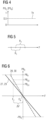
- a frequency range R 1 (first frequency range R 1 ) of frequency oscillations included in the frequency data D is determined, see Fig. 5 .
- a second frequency range R 2 is provided (e.g., determined) in step S5.
- the second frequency range R 2 corresponds to a damping frequency range used for damping mechanical oscillations of mechanical structures 10 - 16, 19 of the wind turbine installations 2, 2' in step S3.
- step S5 it is determined in step S5 if the first frequency range R 1 overlaps at least partially with the second frequency range R 2 .
- a droop characteristic 27, 28 ( Fig. 6 ) for the grid-forming component 5, 5' is determined based on the determined current power output PG C of the one or more generator devices 14.
- a seventh step S7 of the method the power output PB of the grid-forming component 5, 5' is controlled based on the determined frequency deviation ⁇ F and the determined (e.g., selected) droop characteristic 27, 28.
- Fig. 6 shows two different (e.g., predetermined) droop characteristics 27, 28 (first and second droop characteristics 27, 28) for the grid-forming component 5, 5'.
- a respective droop characteristic 27, 28 defines the (e.g., linear) dependency of a desired power output PB D of the grid-forming component 5, 5' on the frequency F of the electrical grid 4, 4'.
- the two droop characteristics 27, 28 shown in Fig. 6 differ from each other by their gradient 29, 30, with the second droop characteristic 28 having a larger gradient (i.e., being steeper) than the first droop characteristic 27.
- applying the second droop characteristic 28 for controlling the power output PB of the grid-forming component 5, 5' allows a faster frequency regulation of the grid 4, 4'.
- the grid-forming component 5, 5' will provide a positive power output PB D for regulating the grid frequency F.
- the energy storage control unit 24 of the grid-forming component 5, 5' will control the energy storage device 6, 6' of the grid-forming component 5, 5' based on a desired power output PB D2 , as illustrated in Fig. 6 .
- This will lead to a fast regulation of the grid 4, 4'.
- an interference of the frequency regulation of the grid 4, 4' with other functions of the wind power plant 1, 1' e.g., the active oscillation damping in step S3 can be kept small.
- the energy storage control unit 24 of the grid-forming component 5, 5' will control the energy storage device 6, 6' of the grid-forming component 5, 5' based on a desired power output PB D1 which is smaller than PB D2 . This will lead to a slower regulation of the grid 4, 4'.
- Such a slow reaction of the grid-forming component 5, 5' helps to increase the lifetime of the grid-forming component 5, 5', in particular of the energy storage device 6, 6' of the grid-forming component 5, 5'.
- Steps S6 and S7 may be carried out only, if it is determined in step S2 that the percentage of the current power output to the rated power output of at least one of the one or more generator devices 14 is above the predetermined threshold Th.
- steps S6 and S7 may be carried out only, if it is determined in step S5 that the first and second frequency ranges R1, R2 overlap at least partially with each other.
Landscapes
- Engineering & Computer Science (AREA)
- Power Engineering (AREA)
- Life Sciences & Earth Sciences (AREA)
- Sustainable Development (AREA)
- Sustainable Energy (AREA)
- Chemical & Material Sciences (AREA)
- Combustion & Propulsion (AREA)
- Mechanical Engineering (AREA)
- General Engineering & Computer Science (AREA)
- Control Of Eletrric Generators (AREA)
Priority Applications (4)
| Application Number | Priority Date | Filing Date | Title |
|---|---|---|---|
| EP23162625.0A EP4432505A1 (de) | 2023-03-17 | 2023-03-17 | Verfahren zur steuerung einer windenergieanlage, computerprogrammprodukt und windenergieanlage |
| EP24707451.1A EP4681306A1 (de) | 2023-03-17 | 2024-02-19 | Verfahren zur steuerung einer windenergieanlage, computerprogrammprodukt und windenergieanlage |
| CN202480019124.6A CN120814135A (zh) | 2023-03-17 | 2024-02-19 | 用于控制风力发电站的方法、计算机程序产品、以及风力发电站 |
| PCT/EP2024/054105 WO2024193917A1 (en) | 2023-03-17 | 2024-02-19 | Method for controlling a wind power plant, computer program product and wind power plant |
Applications Claiming Priority (1)
| Application Number | Priority Date | Filing Date | Title |
|---|---|---|---|
| EP23162625.0A EP4432505A1 (de) | 2023-03-17 | 2023-03-17 | Verfahren zur steuerung einer windenergieanlage, computerprogrammprodukt und windenergieanlage |
Publications (1)
| Publication Number | Publication Date |
|---|---|
| EP4432505A1 true EP4432505A1 (de) | 2024-09-18 |
Family
ID=85704686
Family Applications (2)
| Application Number | Title | Priority Date | Filing Date |
|---|---|---|---|
| EP23162625.0A Pending EP4432505A1 (de) | 2023-03-17 | 2023-03-17 | Verfahren zur steuerung einer windenergieanlage, computerprogrammprodukt und windenergieanlage |
| EP24707451.1A Pending EP4681306A1 (de) | 2023-03-17 | 2024-02-19 | Verfahren zur steuerung einer windenergieanlage, computerprogrammprodukt und windenergieanlage |
Family Applications After (1)
| Application Number | Title | Priority Date | Filing Date |
|---|---|---|---|
| EP24707451.1A Pending EP4681306A1 (de) | 2023-03-17 | 2024-02-19 | Verfahren zur steuerung einer windenergieanlage, computerprogrammprodukt und windenergieanlage |
Country Status (3)
| Country | Link |
|---|---|
| EP (2) | EP4432505A1 (de) |
| CN (1) | CN120814135A (de) |
| WO (1) | WO2024193917A1 (de) |
Citations (4)
| Publication number | Priority date | Publication date | Assignee | Title |
|---|---|---|---|---|
| US20140316592A1 (en) * | 2011-06-14 | 2014-10-23 | Vestas Wind Systems A/S | Selective droop response control for a wind turbine power plant |
| WO2021028198A1 (en) | 2019-08-14 | 2021-02-18 | Siemens Gamesa Renewable Energy A/S | Control of wind turbine during mechanical oscillation damping |
| CN114336676A (zh) * | 2021-12-17 | 2022-04-12 | 中国长江三峡集团有限公司 | 一种dfig风机参与一次调频的装置及控制方法 |
| US20220307472A1 (en) * | 2019-05-09 | 2022-09-29 | Vestas Wind Systems A/S | Wind turbine control using predicted steady-state deflection |
-
2023
- 2023-03-17 EP EP23162625.0A patent/EP4432505A1/de active Pending
-
2024
- 2024-02-19 WO PCT/EP2024/054105 patent/WO2024193917A1/en not_active Ceased
- 2024-02-19 EP EP24707451.1A patent/EP4681306A1/de active Pending
- 2024-02-19 CN CN202480019124.6A patent/CN120814135A/zh active Pending
Patent Citations (4)
| Publication number | Priority date | Publication date | Assignee | Title |
|---|---|---|---|---|
| US20140316592A1 (en) * | 2011-06-14 | 2014-10-23 | Vestas Wind Systems A/S | Selective droop response control for a wind turbine power plant |
| US20220307472A1 (en) * | 2019-05-09 | 2022-09-29 | Vestas Wind Systems A/S | Wind turbine control using predicted steady-state deflection |
| WO2021028198A1 (en) | 2019-08-14 | 2021-02-18 | Siemens Gamesa Renewable Energy A/S | Control of wind turbine during mechanical oscillation damping |
| CN114336676A (zh) * | 2021-12-17 | 2022-04-12 | 中国长江三峡集团有限公司 | 一种dfig风机参与一次调频的装置及控制方法 |
Non-Patent Citations (1)
| Title |
|---|
| ROOZBEHANI SAM ET AL: "Frequency control of islanded wind-powered microgrid based on coordinated robust dynamic droop power sharing", IET GENERATION, TRANSMISSION&DISTRIBUTION, IET, UK, vol. 13, no. 21, 5 November 2019 (2019-11-05), pages 4968 - 4977, XP006085625, ISSN: 1751-8687, DOI: 10.1049/IET-GTD.2019.0410 * |
Also Published As
| Publication number | Publication date |
|---|---|
| CN120814135A (zh) | 2025-10-17 |
| EP4681306A1 (de) | 2026-01-21 |
| WO2024193917A1 (en) | 2024-09-26 |
Similar Documents
| Publication | Publication Date | Title |
|---|---|---|
| US10418925B2 (en) | Wind turbine providing grid support | |
| US9450416B2 (en) | Wind turbine generator controller responsive to grid frequency change | |
| US8994200B2 (en) | Power system frequency inertia for power generation system | |
| CN102301584B (zh) | 风力涡轮系统和稳定公用系统的频率和功率摆动的方法 | |
| EP2306001B1 (de) | Mehrzweckenergiespeicher für erneuerbare Quellen | |
| CA2748459C (en) | Adaptive voltage control for wind turbines | |
| EP2463519B1 (de) | Windturbinegenerator, steuerverfahren für den windturbinegenerator, windturbineerzeugungssystem und steuerverfahren für das windturbineerzeugungssystem | |
| EP1914420B1 (de) | Windenergieanlage und Verfahren zur Steuerung der Ausgangsleistung einer Windenergieanlage | |
| EP1931009A2 (de) | Verfahren zur Synchronisierung mehrerer Generatoren | |
| EP4432505A1 (de) | Verfahren zur steuerung einer windenergieanlage, computerprogrammprodukt und windenergieanlage | |
| EP2594786A1 (de) | Verfahren zum Betrieb einer Windturbine | |
| US20250163593A1 (en) | Wind power plant and method for operating a wind power plant | |
| EP4607737A1 (de) | Verfahren zur steuerung einer windenergieanlage, computerprogrammprodukt und windenergieanlage |
Legal Events
| Date | Code | Title | Description |
|---|---|---|---|
| PUAI | Public reference made under article 153(3) epc to a published international application that has entered the european phase |
Free format text: ORIGINAL CODE: 0009012 |
|
| STAA | Information on the status of an ep patent application or granted ep patent |
Free format text: STATUS: THE APPLICATION HAS BEEN PUBLISHED |
|
| AK | Designated contracting states |
Kind code of ref document: A1 Designated state(s): AL AT BE BG CH CY CZ DE DK EE ES FI FR GB GR HR HU IE IS IT LI LT LU LV MC ME MK MT NL NO PL PT RO RS SE SI SK SM TR |