EP4434474A1 - Instrument, système et procédé de pulvérisation de liquides - Google Patents
Instrument, système et procédé de pulvérisation de liquides Download PDFInfo
- Publication number
- EP4434474A1 EP4434474A1 EP23163809.9A EP23163809A EP4434474A1 EP 4434474 A1 EP4434474 A1 EP 4434474A1 EP 23163809 A EP23163809 A EP 23163809A EP 4434474 A1 EP4434474 A1 EP 4434474A1
- Authority
- EP
- European Patent Office
- Prior art keywords
- instrument
- gas
- liquid
- flow
- stream
- Prior art date
- Legal status (The legal status is an assumption and is not a legal conclusion. Google has not performed a legal analysis and makes no representation as to the accuracy of the status listed.)
- Pending
Links
- 239000007788 liquid Substances 0.000 title claims abstract description 188
- 238000005507 spraying Methods 0.000 title claims description 22
- 238000000034 method Methods 0.000 title claims description 19
- 239000007921 spray Substances 0.000 claims abstract description 20
- 239000007789 gas Substances 0.000 description 164
- 230000004888 barrier function Effects 0.000 description 5
- 239000011248 coating agent Substances 0.000 description 5
- 238000000576 coating method Methods 0.000 description 5
- 239000003085 diluting agent Substances 0.000 description 5
- 239000000203 mixture Substances 0.000 description 4
- XLYOFNOQVPJJNP-UHFFFAOYSA-N water Substances O XLYOFNOQVPJJNP-UHFFFAOYSA-N 0.000 description 4
- 239000003054 catalyst Substances 0.000 description 3
- 239000000017 hydrogel Substances 0.000 description 3
- 230000002209 hydrophobic effect Effects 0.000 description 3
- XKRFYHLGVUSROY-UHFFFAOYSA-N Argon Chemical compound [Ar] XKRFYHLGVUSROY-UHFFFAOYSA-N 0.000 description 2
- IJGRMHOSHXDMSA-UHFFFAOYSA-N Atomic nitrogen Chemical compound N#N IJGRMHOSHXDMSA-UHFFFAOYSA-N 0.000 description 2
- CURLTUGMZLYLDI-UHFFFAOYSA-N Carbon dioxide Chemical compound O=C=O CURLTUGMZLYLDI-UHFFFAOYSA-N 0.000 description 2
- 239000000853 adhesive Substances 0.000 description 2
- 230000001070 adhesive effect Effects 0.000 description 2
- 239000012530 fluid Substances 0.000 description 2
- 239000000499 gel Substances 0.000 description 2
- 230000001575 pathological effect Effects 0.000 description 2
- 230000003187 abdominal effect Effects 0.000 description 1
- 210000003815 abdominal wall Anatomy 0.000 description 1
- 238000009825 accumulation Methods 0.000 description 1
- 229910052786 argon Inorganic materials 0.000 description 1
- 230000036760 body temperature Effects 0.000 description 1
- 229910002092 carbon dioxide Inorganic materials 0.000 description 1
- 239000001569 carbon dioxide Substances 0.000 description 1
- 239000003431 cross linking reagent Substances 0.000 description 1
- 230000001419 dependent effect Effects 0.000 description 1
- 238000011161 development Methods 0.000 description 1
- 230000018109 developmental process Effects 0.000 description 1
- 239000011261 inert gas Substances 0.000 description 1
- 229910052757 nitrogen Inorganic materials 0.000 description 1
- 229910052756 noble gas Inorganic materials 0.000 description 1
- 150000002835 noble gases Chemical class 0.000 description 1
- 210000000056 organ Anatomy 0.000 description 1
- 229920000642 polymer Polymers 0.000 description 1
- 229920002635 polyurethane Polymers 0.000 description 1
- 239000004814 polyurethane Substances 0.000 description 1
- 230000002265 prevention Effects 0.000 description 1
- 239000000376 reactant Substances 0.000 description 1
- 238000001228 spectrum Methods 0.000 description 1
- 239000000126 substance Substances 0.000 description 1
- 238000011477 surgical intervention Methods 0.000 description 1
- 230000032258 transport Effects 0.000 description 1
Images


Classifications
-
- A—HUMAN NECESSITIES
- A61—MEDICAL OR VETERINARY SCIENCE; HYGIENE
- A61B—DIAGNOSIS; SURGERY; IDENTIFICATION
- A61B17/00—Surgical instruments, devices or methods
- A61B17/00491—Surgical glue applicators
-
- A—HUMAN NECESSITIES
- A61—MEDICAL OR VETERINARY SCIENCE; HYGIENE
- A61B—DIAGNOSIS; SURGERY; IDENTIFICATION
- A61B17/00—Surgical instruments, devices or methods
- A61B17/00234—Surgical instruments, devices or methods for minimally invasive surgery
-
- A—HUMAN NECESSITIES
- A61—MEDICAL OR VETERINARY SCIENCE; HYGIENE
- A61M—DEVICES FOR INTRODUCING MEDIA INTO, OR ONTO, THE BODY; DEVICES FOR TRANSDUCING BODY MEDIA OR FOR TAKING MEDIA FROM THE BODY; DEVICES FOR PRODUCING OR ENDING SLEEP OR STUPOR
- A61M11/00—Sprayers or atomisers specially adapted for therapeutic purposes
- A61M11/02—Sprayers or atomisers specially adapted for therapeutic purposes operated by air or other gas pressure applied to the liquid or other product to be sprayed or atomised
-
- A—HUMAN NECESSITIES
- A61—MEDICAL OR VETERINARY SCIENCE; HYGIENE
- A61M—DEVICES FOR INTRODUCING MEDIA INTO, OR ONTO, THE BODY; DEVICES FOR TRANSDUCING BODY MEDIA OR FOR TAKING MEDIA FROM THE BODY; DEVICES FOR PRODUCING OR ENDING SLEEP OR STUPOR
- A61M31/00—Devices for introducing or retaining media, e.g. remedies, in cavities of the body
-
- B—PERFORMING OPERATIONS; TRANSPORTING
- B05—SPRAYING OR ATOMISING IN GENERAL; APPLYING FLUENT MATERIALS TO SURFACES, IN GENERAL
- B05B—SPRAYING APPARATUS; ATOMISING APPARATUS; NOZZLES
- B05B1/00—Nozzles, spray heads or other outlets, with or without auxiliary devices such as valves, heating means
- B05B1/34—Nozzles, spray heads or other outlets, with or without auxiliary devices such as valves, heating means designed to influence the nature of flow of the liquid or other fluent material, e.g. to produce swirl
- B05B1/3405—Nozzles, spray heads or other outlets, with or without auxiliary devices such as valves, heating means designed to influence the nature of flow of the liquid or other fluent material, e.g. to produce swirl to produce swirl
-
- B—PERFORMING OPERATIONS; TRANSPORTING
- B05—SPRAYING OR ATOMISING IN GENERAL; APPLYING FLUENT MATERIALS TO SURFACES, IN GENERAL
- B05B—SPRAYING APPARATUS; ATOMISING APPARATUS; NOZZLES
- B05B12/00—Arrangements for controlling delivery; Arrangements for controlling the spray area
- B05B12/14—Arrangements for controlling delivery; Arrangements for controlling the spray area for supplying a selected one of a plurality of liquids or other fluent materials or several in selected proportions to a spray apparatus, e.g. to a single spray outlet
- B05B12/1472—Arrangements for controlling delivery; Arrangements for controlling the spray area for supplying a selected one of a plurality of liquids or other fluent materials or several in selected proportions to a spray apparatus, e.g. to a single spray outlet separate supply lines supplying different materials to separate outlets of the spraying apparatus
-
- B—PERFORMING OPERATIONS; TRANSPORTING
- B05—SPRAYING OR ATOMISING IN GENERAL; APPLYING FLUENT MATERIALS TO SURFACES, IN GENERAL
- B05B—SPRAYING APPARATUS; ATOMISING APPARATUS; NOZZLES
- B05B7/00—Spraying apparatus for discharge of liquids or other fluent materials from two or more sources, e.g. of liquid and air, of powder and gas
- B05B7/02—Spray pistols; Apparatus for discharge
- B05B7/06—Spray pistols; Apparatus for discharge with at least one outlet orifice surrounding another approximately in the same plane
- B05B7/062—Spray pistols; Apparatus for discharge with at least one outlet orifice surrounding another approximately in the same plane with only one liquid outlet and at least one gas outlet
- B05B7/066—Spray pistols; Apparatus for discharge with at least one outlet orifice surrounding another approximately in the same plane with only one liquid outlet and at least one gas outlet with an inner liquid outlet surrounded by at least one annular gas outlet
-
- B—PERFORMING OPERATIONS; TRANSPORTING
- B05—SPRAYING OR ATOMISING IN GENERAL; APPLYING FLUENT MATERIALS TO SURFACES, IN GENERAL
- B05B—SPRAYING APPARATUS; ATOMISING APPARATUS; NOZZLES
- B05B7/00—Spraying apparatus for discharge of liquids or other fluent materials from two or more sources, e.g. of liquid and air, of powder and gas
- B05B7/02—Spray pistols; Apparatus for discharge
- B05B7/08—Spray pistols; Apparatus for discharge with separate outlet orifices, e.g. to form parallel jets, i.e. the axis of the jets being parallel, to form intersecting jets, i.e. the axis of the jets converging but not necessarily intersecting at a point
- B05B7/0807—Spray pistols; Apparatus for discharge with separate outlet orifices, e.g. to form parallel jets, i.e. the axis of the jets being parallel, to form intersecting jets, i.e. the axis of the jets converging but not necessarily intersecting at a point to form intersecting jets
-
- B—PERFORMING OPERATIONS; TRANSPORTING
- B05—SPRAYING OR ATOMISING IN GENERAL; APPLYING FLUENT MATERIALS TO SURFACES, IN GENERAL
- B05B—SPRAYING APPARATUS; ATOMISING APPARATUS; NOZZLES
- B05B7/00—Spraying apparatus for discharge of liquids or other fluent materials from two or more sources, e.g. of liquid and air, of powder and gas
- B05B7/02—Spray pistols; Apparatus for discharge
- B05B7/10—Spray pistols; Apparatus for discharge producing a swirling discharge
-
- A—HUMAN NECESSITIES
- A61—MEDICAL OR VETERINARY SCIENCE; HYGIENE
- A61B—DIAGNOSIS; SURGERY; IDENTIFICATION
- A61B17/00—Surgical instruments, devices or methods
- A61B17/00491—Surgical glue applicators
- A61B2017/00495—Surgical glue applicators for two-component glue
-
- A—HUMAN NECESSITIES
- A61—MEDICAL OR VETERINARY SCIENCE; HYGIENE
- A61B—DIAGNOSIS; SURGERY; IDENTIFICATION
- A61B17/00—Surgical instruments, devices or methods
- A61B17/00491—Surgical glue applicators
- A61B2017/00522—Sprayers
-
- A—HUMAN NECESSITIES
- A61—MEDICAL OR VETERINARY SCIENCE; HYGIENE
- A61B—DIAGNOSIS; SURGERY; IDENTIFICATION
- A61B90/00—Instruments, implements or accessories specially adapted for surgery or diagnosis and not covered by any of the groups A61B1/00 - A61B50/00, e.g. for luxation treatment or for protecting wound edges
- A61B90/08—Accessories or related features not otherwise provided for
- A61B2090/0815—Implantable devices for insertion in between organs or other soft tissues
- A61B2090/0816—Implantable devices for insertion in between organs or other soft tissues for preventing adhesion
Definitions
- the invention relates to an instrument, preferably for minimally invasive use, with a nozzle arrangement arranged distally on the instrument, which is designed to spray liquids by means of a swirling gas stream, and to a system which has this instrument.
- the invention also relates to a method for spraying liquids.
- pathological adhesions can form between the individual organs and/or the abdominal wall. These pathological adhesions are also known as adhesions, which can lead to serious complications for patients after the procedure.
- adhesion barriers are substances that can be applied to the affected tissue areas to prevent other tissue layers from growing on them.
- the adhesion barriers are advantageously applied by spraying.
- these adhesion barriers are made of two components that first mixed together immediately before or during application.
- WO 0 009 199 A1 describes a device designed to spray a two-component adhesion barrier.
- the device has separate spray nozzles for each of the two components.
- the components are sprayed via a gas stream, the gas stream exiting through circumferential gaps surrounding the nozzles.
- the EP 3 145 417 A1 describes a second device for spraying at least two components using a pressurized gas inside the body of a patient.
- the device has a spray head in which the components emerge separately from one another and are mixed and sprayed by a gas stream that also emerges from the spray head.
- Second spray devices for multiple components are installed in EP 0 951 311 B1 , EP 0 302 411 A1 , EP 2 739 401 A2 , US 2006/189 944 A1 and EP 2 695 626 A1 described.
- EP 2 907 582 B1 describes an externally mixing nozzle in which at least two fluids with different volume flows and/or different viscosities are sprayed.
- JP 2011-194304 A a device for spraying two components forming an adhesive, in which a rotating gas stream is used to spray the components.
- the outlet opening for the gas stream is located centrally between the two separate outlet openings for the components.
- the instrument according to the invention has a nozzle arrangement arranged distally on the instrument, which is designed to spray liquids by means of a swirling gas flow.
- the nozzle arrangement has a nozzle body with a liquid outlet and a gas outlet arrangement.
- the instrument is designed to to discharge a liquid flow through the liquid outlet and the swirling gas flow through the gas outlet arrangement.
- the gas outlet arrangement is arranged such that it encloses the liquid outlet, preferably completely, whereby the swirling gas flow has the largest possible overlap area with the liquid flow.
- the gas flow spreads out from the gas outlet arrangement in a direction of spread with a spray angle determined by the gas outlet arrangement.
- the gas flow is subjected to a vortex flow (hereinafter also referred to as swirl).
- swirl a vortex flow
- the gas flow catches the liquid droplets of the liquid flow in the overlapping area, they are entrained by the gas flow and mixed. Due to the vortex flow (swirl) imposed on the gas flow, additional shear forces act on the liquid droplets of the liquid flow, whereby the liquid droplets are broken up into finer liquid droplets in flight. This makes it possible to achieve a droplet spectrum with smaller droplet sizes.
- the swirling gas flow can thus achieve improved mixing of the liquids outside the nozzle arrangement.
- a special feature of the instrument according to the invention is that the nozzle arrangement generates a swirling gas flow which is used to mix and spray the liquids outside the nozzle arrangement, whereby the gases emerging from the nozzle arrangement Liquids are flowed around and/or through by the swirling gas stream, preferably all the way around.
- the swirl imposed on the gas stream can lead to a larger spray angle of the gas/liquid mixture, which can make the application and distribution of the gas/liquid mixture easier and faster, especially over large areas.
- the liquid droplets of the first liquid stream around which the swirling gas stream flows are entrained and carried along a trajectory from the inside to the outside and/or from the outside to the inside, whereby the droplets are atomized due to the shear forces acting on them.
- the swirl imposed on the gas stream also ensures that the axial exit velocity of the gas/liquid mixture is reduced when the droplet size is small, which enables the liquid to be applied evenly to the tissue.
- the liquid to be sprayed is preferably composed of several components that react with one another.
- the liquid to be sprayed can, for example, be a gel that is initially present in at least two components. It is preferred that the gel is a hydrogel.
- a hydrogel is a polymer that contains water and is simultaneously insoluble in water.
- the hydrogel is based on polyurethane.
- the components of the liquid can be, for example, a prepolymer and a crosslinking agent. reactants. These components react with each other when mixed, and the reaction rate at which these components react with each other is comparatively high.
- the components can, for example, have reacted (completely) with each other within 60 s or less, 50 s or less, and 40 s or less at room or body temperature.
- the components are therefore preferably mixed outside the nozzle arrangement in order to avoid clogging of the nozzle arrangement after use.
- the nozzle arrangement has the first liquid outlet and a second liquid outlet through which a second liquid stream can be discharged, the second liquid outlet being arranged at a distance from the first liquid outlet.
- the second liquid outlet is preferably a separate liquid outlet.
- the first liquid outlet is preferably associated with a first liquid capillary through which a first feed stream of the first liquid is guided to the nozzle arrangement, and the second liquid outlet is preferably associated with a second liquid capillary through which a second feed stream of the second liquid is guided to the nozzle arrangement.
- the two liquids to be mixed can thus be transported separately from a supply device to the nozzle arrangement of the instrument and there mixed and sprayed outside the nozzle arrangement by the swirling gas stream.
- the distance between the first and the second liquid outlet can be between 0.8 and 1.5 mm, preferably 1.4 mm, which ensures good mixing of the liquids and at the same time prevents clogging of the nozzle arrangement.
- the gas outlet arrangement preferably has a first gas outlet opening which is arranged concentrically to the first liquid outlet.
- the gas outlet opening can be an annular gap opening, for example.
- the annular gap opening can have a width of 0.08 to 0.15 mm, preferably a width of 0.1.
- the gas outlet opening can also be divided into several annular gap segments.
- the gas outlet arrangement can have several gas outlet openings which are arranged on a circle defined concentrically to the first liquid outlet.
- the gas outlet arrangement has a second gas outlet opening which is arranged concentrically to the second liquid outlet, wherein the first gas outlet opening and the second gas outlet opening are each designed to discharge a swirling gas flow.
- the first liquid outlet and the second liquid outlet are thus each enclosed by a gas outlet opening.
- the swirling gas flow captures the liquids exiting from the liquid outlets and sprays them, wherein the two resulting spray cones overlap outside the nozzle arrangement. In the overlap region, there is an improved mixing of the two liquid flows.
- the swirling gas streams exiting through the first gas outlet opening and the second gas outlet opening are subjected to a swirl rotating in the same direction or rotating against each other.
- first liquid outlet and the second liquid outlet are arranged at a distance from one another in a flow body which defines a central axis M.
- the gas outlet arrangement has in particular a gas outlet opening which surrounds the flow body and is preferably arranged concentrically to the central axis M of the flow body.
- the flow body preferably has a convex outer contour, whereby the gas flow follows the outer contour of the flow body s and entrainment of the two liquids can be improved.
- the surface of the flow body s is preferably designed with a hydrophobic coating. This can prevent drops from adhering to the distal end of the instrument, which could otherwise lead to an accumulation of hardened (reacting with each other) liquid drops, which in turn can clog the gas outlet opening and/or the liquid outlets.
- the swirling gas stream or streams preferably completely surround the first liquid stream and the second liquid stream, so that the liquid streams and the gas streams are in front of the
- the nozzle arrangement should overlap as much as possible. This allows the largest possible mixing zone for the liquids to be achieved.
- At least one gas supply channel opens into the nozzle body, wherein the gas outlet arrangement can be supplied with a gas supply flow via the gas supply channel.
- at least one swirl generating means is accommodated in the nozzle body, which is designed to impart a predetermined swirl to the gas supply flow.
- the swirl generating means can, for example, be designed as a swirl body that is arranged in such a way that the predetermined swirl is impressed on the gas supply flow.
- the swirl generating means can also be designed as a connecting channel through which the gas supply flow flows into the gas outlet opening in such a way that the predetermined swirl is impressed on it.
- the swirl angle which describes the angle of the swirl to the axis of rotation of the swirl, can in particular be greater than 15°, preferably greater than 20° and particularly preferably greater than 25°.
- the first liquid outlet and/or the second liquid outlet are arranged distally from the instrument, which makes it more difficult for liquid droplets to adhere to the distal end of the instrument if the spraying process is interrupted.
- the gas flows over the liquid outlets, so that liquid droplets adhering to the liquid outlets are entrained by the gas flow that has already flowed out, even if the liquid flow and the gas flow are interrupted almost simultaneously.
- the instrument further comprises an elongate shaft in which the gas supply channel and the liquid capillary for each liquid outlet are arranged.
- the instrument may also comprise a proximally arranged interface device which is connectable to a supply device.
- the supply device may be configured to supply the instrument with the liquids and with the gas supply stream.
- the instrument also has a control unit which is designed to interrupt the first liquid flow and, if present, the second liquid flow when the spraying process ends before the gas flow and the second gas flow, if present.
- the control unit can also be designed to initiate the first gas flow before the first liquid flow when the spraying process starts and, if present, also initiate the second gas flow before the second liquid flow. Both measures can help to prevent liquid drops from accumulating at the distal end of the instrument.
- the method according to the invention for spraying liquids by means of an instrument comprises the following:
- first swirling gas stream and/or the second swirling gas stream envelop the first liquid stream and the second liquid stream, preferably completely.
- the first liquid stream and the second liquid stream are interrupted before the first gas stream and, if present, the second gas stream.
- the first gas stream and, if present, the second gas stream are introduced before the first liquid stream and the second liquid stream.
- the system according to the invention comprises an instrument of the above type and a supply device for feeding the instrument with the required operating resources.
- Operating resources can be, for example, fluids such as gases or liquids, and/or an electrical voltage, in particular a high-frequency alternating voltage.
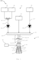
- FIG. 1 a system 100 for supplying, mixing and spraying several liquid components is shown.
- the system 100 has an instrument 10 and a supply device 28.
- the instrument 10 is preferably designed for minimally invasive use, in particular for laparoscopic use.
- the instrument 10 has a nozzle arrangement 11 which is arranged distally on the instrument 10.
- the nozzle arrangement 11 is designed to spray liquids 13 and 13' by means of a first and/or a second swirling gas flow 14, 14'.
- the nozzle arrangement 11 has a first liquid outlet 15 and a second liquid outlet 15' through which a first liquid stream 17 of the first liquid 13 and a second liquid stream 17' of the second liquid 13' flow.
- the nozzle arrangement 11 also has a gas outlet arrangement 16 which is designed to discharge the first and/or second gas stream 14, 14'.
- the instrument 10 has an elongated shaft 31 in which the liquids 13 and 13' to be sprayed as well as the gas for generating the swirling gas flow are transported.
- the instrument 10 has an interface device 26.
- the interface device 26 is designed to be connected to a supply device 28.
- the supply device 28 provides the liquid 13 and the second liquid 13'.
- the elongated shaft 31 of the instrument 10 has a liquid capillary 25 associated with the liquid 13 and a second separate liquid capillary 25 ⁇ associated with the second liquid 13'.
- the liquids 13 and 13 ⁇ are transported via the liquid capillaries 25 and 25' from the interface device 26 at the proximal end 33 of the instrument 10 to the nozzle arrangement 11 at the distal end 32 of the instrument 10.
- a gas supply channel 18 is also arranged in the elongated shaft 31 of the instrument 10, which transports a gas supply stream 19 from the interface device 26 at the proximal end 33 to the nozzle arrangement 11 at the distal end 32 of the instrument 10.
- the supply device 28 has a first source 34 for a first component, a second source 35 for a second component, a third source 36 for a diluent and a fourth source 37 for a gas.
- the first component can be a prepolymer, for example.
- the prepolymer in the first source 34 can have a relatively high viscosity, for example greater than 9 mPa ⁇ s, which is why diluent from the third source 36 can be mixed into it in the mixing device 40.
- the diluent can be water, for example.
- the first component mixed with the diluent forms the first liquid 13, which after premixing can be output to the interface device 26 via a first dosing unit 38.
- the second component can be a catalyst.
- the second component forms the second liquid 13', which can be output from the supply device 28 to the interface device 26 via a separate dosing unit 39.
- the second liquid can be, for example, a catalyst for the first liquid.
- the supply device 28 also has a fourth source 37 for the gas.
- the gas is preferably carbon dioxide or air, or an inert gas, e.g. nitrogen or noble gases such as argon or the like.
- the gas from the fourth source 37 is made available by the supply device 28 via the interface device 26 for the instrument 10.
- the sources 34, 35, 36, 37 can, for example, be reservoirs or tanks in which the components are stored. Alternatively, sources 34, 35, 36, 37 can also be connections to a supply line of the component.
- the instrument 10 also has a control unit 30 which is designed to interrupt the liquid streams 17, 17' before the gas streams 14, 14', 14" when the spraying process ends.
- the control unit 30 is also designed to activate the liquid streams 17 and 17' after the gas streams 14, 14', 14" when the spraying process begins.
- Figure 2 shows a cross section through the nozzle body 12 of a nozzle arrangement 11 of the instrument 10 according to a first embodiment along the Figure 4 drawn section plane A.
- a gas supply channel 18 is provided in the nozzle body 12, through which the gas supply stream 19 is guided.
- the gas supply stream 19 points out of the drawing plane.
- a first liquid outlet 15 and a second liquid outlet 15' are also arranged in the nozzle body 12.
- the first liquid flow 17 is discharged through the first liquid outlet 15.
- the second liquid outlet 15' is in turn provided for the second liquid flow 17'.
- the liquid outlets 15 and 15' are each surrounded by a gas outlet opening 21 and 21', which together form the gas outlet arrangement 16.
- a swirl generating means is accommodated in the nozzle body 12.
- the swirl generating means is formed by connecting channels 41, 41 ⁇ , via which the gas outlet openings 21 and 21' are fluidically connected to the gas supply channel 18.
- the connecting channels 41 are arranged in such a way that the central gas supply flow 19 is divided into two partial gas flows.
- the partial gas flows are guided by the connecting channels 41, 41' into the gas outlet openings 21, 21 ⁇ in such a way that a first swirl-affected gas flow 14 is formed in the first gas outlet opening 21 and a second swirl-affected gas flow 14' is formed in the second gas outlet opening 21 ⁇ .
- the partial gas flows are introduced through the connecting channels 41, 41' preferably tangentially to the liquid outlets 15, 15' into the gas outlet openings 21, 21 ⁇ of the gas outlet arrangement 16.
- the partial flows can be introduced at an inflow angle relative to a Cross-sectional plane of the nozzle body 12 into the gas outlet openings 21, 21'.
- the connecting channels 41, 41' are arranged in this embodiment such that the first and the second gas stream 14, 14' flow in the same rotating direction.
- swirl bodies 20, 20' can be arranged in the gas outlet openings 21, 21', which provide the first gas stream 14 and the second gas stream 14' with a swirl.
- Figure 3 is a cross section along the cutting plane A from Figure 5 shown according to a second embodiment.
- the connecting channels 41 are arranged such that the gas flows 14 and 14' rotate in opposite directions.
- Figure 3 shows a cross section along the section plane A from Figure 5 .
- a gas outlet opening 21 is arranged concentrically around the first liquid outlet 15.
- the first gas outlet opening 21 is designed as an annular gap in this example.
- the central gas supply channel 18 is connected to the first gas outlet opening 21 via a connecting channel 41.
- a second gas outlet opening 21 ⁇ is also arranged concentrically around the second liquid outlet 15'.
- the second gas outlet opening 21 ⁇ is also designed as an annular gap, with the second gas outlet opening 21 being connected to the gas supply channel 18 via a connecting channel 41'.
- the connecting channels 41 are arranged in such a way that the gas supply flow 19 is divided into two partial flows, which are given a swirl that points counterclockwise.
- the first swirling gas flow 14 and the second swirling gas flow 14 ⁇ rotate in the same direction.
- the first liquid outlet 15 and the second liquid outlet 15' protrude distally from the instrument 10 by the distance V.
- Figure 5 is a longitudinal section of the second example of the nozzle arrangement 11. Also with respect to Figure 5 what has been described so far applies accordingly based on the reference symbols.
- Figure 5 differs from Figure 4 in that the connecting channels 41 are arranged such that the swirling gas stream 14 and the second swirling gas stream 14' rotate in opposite directions.
- Figure 6 shows a distal plan view of the nozzle arrangement 11 according to the third embodiment.
- the liquid outlets 15 and 15' are arranged in a common flow body 22.
- the flow body 22 is enclosed by the gas outlet arrangement 16.
- the gas outlet arrangement 16 has a gas outlet opening 21" which surrounds the flow body 22.
- This gas outlet opening 21" is also designed as an annular gap.
- a swirl body 20 is provided in the nozzle body 12, which imparts an additional angular momentum to the gas supply flow 19.
- Figure 7 shows an embodiment of the nozzle arrangement in which the two liquid outlets 15 and 15' are arranged in the flow body 22.
- the flow body 22 is surrounded by the gas outlet opening 21".
- At least one swirl body 20 is arranged in the gas outlet opening 21", which imparts an angular momentum to the gas supply stream 19.
- the outer contour of the flow body 22 is designed as a cone. It is also possible for the outer contour of the flow body 22 to be designed as a truncated cone.
- the surface 23 of the flow body 22 has an additional coating 27.
- the coating can have hydrophobic properties, for example.
- Figure 8 shows a second example of a nozzle arrangement in which the liquid outlets 15 and 15' are provided in a flow body 22.
- the flow body 22 has a convex outer contour.
- a coating of the surface 23 of the flow body 22 is provided, which can be designed to be hydrophobic, for example.
- the mass flows ⁇ of the first gas flow 14 or second gas flow 14 ⁇ or third gas flow 14" and the first liquid flow 17 or second liquid flow 17' are shown over time t.
- the respective mass flows are designated ⁇ 14, ⁇ 14', ⁇ 14" and ⁇ 17, ⁇ 17'.
- the mass flow ⁇ 14, ⁇ 14', ⁇ 14" of the gas flow 14 or 14' or 14" is introduced first, before the mass flows ⁇ 17, ⁇ 17' of the liquid flows 17, 17' are introduced.
- the mass flows ⁇ 17, ⁇ 17' of the liquid flows 17, 17' are interrupted before the mass flows ⁇ 14, ⁇ 14', ⁇ 14" of the gas flows 14, 14', 14".
- the instrument 10 serves to spray several mutually reactive liquids 13, 13 ⁇ by means of at least one swirling gas stream 14, 14', 14" and to mix them outside the nozzle arrangement 11 of the instrument 10.
- the nozzle arrangement 11 of the instrument has a nozzle body 12 with at least one liquid outlet 15, 15' through which one or more liquids 13, 13 ⁇ can be dispensed, and a gas outlet arrangement 16 through which the at least one swirling gas stream 14, 14', 14" can be dispensed, wherein the gas outlet arrangement encloses the at least one liquid outlet, preferably completely.
Landscapes
- Health & Medical Sciences (AREA)
- Life Sciences & Earth Sciences (AREA)
- Surgery (AREA)
- Heart & Thoracic Surgery (AREA)
- Biomedical Technology (AREA)
- Animal Behavior & Ethology (AREA)
- General Health & Medical Sciences (AREA)
- Public Health (AREA)
- Veterinary Medicine (AREA)
- Engineering & Computer Science (AREA)
- Nuclear Medicine, Radiotherapy & Molecular Imaging (AREA)
- Medical Informatics (AREA)
- Molecular Biology (AREA)
- Hematology (AREA)
- Anesthesiology (AREA)
- Nozzles (AREA)
Priority Applications (5)
| Application Number | Priority Date | Filing Date | Title |
|---|---|---|---|
| EP23163809.9A EP4434474A1 (fr) | 2023-03-23 | 2023-03-23 | Instrument, système et procédé de pulvérisation de liquides |
| JP2024033977A JP2024137779A (ja) | 2023-03-23 | 2024-03-06 | 液体を噴霧するための器具、システムおよび方法 |
| US18/608,085 US20240315684A1 (en) | 2023-03-23 | 2024-03-18 | Medical instrument, system, and method for spraying liquids |
| KR1020240037012A KR20240143896A (ko) | 2023-03-23 | 2024-03-18 | 액체를 분사하기 위한 기기, 시스템 및 방법 |
| CN202410326540.2A CN118680653A (zh) | 2023-03-23 | 2024-03-21 | 用于喷洒液体的器械、系统和方法 |
Applications Claiming Priority (1)
| Application Number | Priority Date | Filing Date | Title |
|---|---|---|---|
| EP23163809.9A EP4434474A1 (fr) | 2023-03-23 | 2023-03-23 | Instrument, système et procédé de pulvérisation de liquides |
Publications (1)
| Publication Number | Publication Date |
|---|---|
| EP4434474A1 true EP4434474A1 (fr) | 2024-09-25 |
Family
ID=85727044
Family Applications (1)
| Application Number | Title | Priority Date | Filing Date |
|---|---|---|---|
| EP23163809.9A Pending EP4434474A1 (fr) | 2023-03-23 | 2023-03-23 | Instrument, système et procédé de pulvérisation de liquides |
Country Status (5)
| Country | Link |
|---|---|
| US (1) | US20240315684A1 (fr) |
| EP (1) | EP4434474A1 (fr) |
| JP (1) | JP2024137779A (fr) |
| KR (1) | KR20240143896A (fr) |
| CN (1) | CN118680653A (fr) |
Citations (13)
| Publication number | Priority date | Publication date | Assignee | Title |
|---|---|---|---|---|
| US4335677A (en) * | 1979-10-25 | 1982-06-22 | Sumitomo Light Metal Industries, Ltd. | Coating of the inner surface of tubes |
| EP0302411A2 (fr) | 1987-08-01 | 1989-02-08 | Hoechst Aktiengesellschaft | Tête de pulvérisation pour l'application d'un matériau à plusieurs composants à l'aide d'un gaz |
| US5368563A (en) | 1991-12-18 | 1994-11-29 | Micromedics, Inc. | Sprayer assembly for physiologic glue |
| WO1998020931A1 (fr) * | 1996-11-15 | 1998-05-22 | Bristol-Myers Squibb Company | Dispositifs et procedes utilises pour appliquer un melange de deux composants liquides ou davantage pour former un biomateriau |
| WO2000009199A1 (fr) | 1998-08-14 | 2000-02-24 | Incept Llc | Procedes et appareil servant a former des hydrogels in situ |
| JP2000354797A (ja) * | 1999-06-17 | 2000-12-26 | Sumitomo Bakelite Co Ltd | 生体組織接着剤塗布用具 |
| US20060189944A1 (en) | 2005-02-08 | 2006-08-24 | Campbell Patrick K | Spray for fluent materials |
| JP2011194304A (ja) | 2010-03-18 | 2011-10-06 | Olympus Corp | 接着剤塗布装置 |
| EP2695626A1 (fr) | 2012-08-10 | 2014-02-12 | Nordson Corporation | Dispositif de déchargement d'un liquide réactif |
| EP2739401A2 (fr) | 2011-06-05 | 2014-06-11 | Omrix Biopharmaceuticals Ltd. | Dispositif pour pulvériser et / ou mélanger des fluides à proximité d'une surface |
| WO2015176905A1 (fr) | 2014-05-22 | 2015-11-26 | Medmix Systems Ag | Applicateur de pulvérisation laparoscopique et adaptateur |
| EP2907582B1 (fr) | 2014-02-17 | 2017-09-06 | Erbe Elektromedizin GmbH | Procédé et buse permettant de mélanger et de pulvériser des fluides médicaux |
| WO2019065192A1 (fr) * | 2017-09-29 | 2019-04-04 | ランズバーグ・インダストリー株式会社 | Dispositif de pulvérisation pneumatique de matériau de revêtement |
-
2023
- 2023-03-23 EP EP23163809.9A patent/EP4434474A1/fr active Pending
-
2024
- 2024-03-06 JP JP2024033977A patent/JP2024137779A/ja active Pending
- 2024-03-18 US US18/608,085 patent/US20240315684A1/en active Pending
- 2024-03-18 KR KR1020240037012A patent/KR20240143896A/ko active Pending
- 2024-03-21 CN CN202410326540.2A patent/CN118680653A/zh active Pending
Patent Citations (15)
| Publication number | Priority date | Publication date | Assignee | Title |
|---|---|---|---|---|
| US4335677A (en) * | 1979-10-25 | 1982-06-22 | Sumitomo Light Metal Industries, Ltd. | Coating of the inner surface of tubes |
| EP0302411A2 (fr) | 1987-08-01 | 1989-02-08 | Hoechst Aktiengesellschaft | Tête de pulvérisation pour l'application d'un matériau à plusieurs composants à l'aide d'un gaz |
| US5368563A (en) | 1991-12-18 | 1994-11-29 | Micromedics, Inc. | Sprayer assembly for physiologic glue |
| EP0951311B1 (fr) | 1996-11-15 | 2007-03-28 | Bristol-Myers Squibb Company | Dispositifs utililsés por appliquer un mélange de deux ou plusieurs composants liquides pour former un biomateriau |
| WO1998020931A1 (fr) * | 1996-11-15 | 1998-05-22 | Bristol-Myers Squibb Company | Dispositifs et procedes utilises pour appliquer un melange de deux composants liquides ou davantage pour former un biomateriau |
| WO2000009199A1 (fr) | 1998-08-14 | 2000-02-24 | Incept Llc | Procedes et appareil servant a former des hydrogels in situ |
| JP2000354797A (ja) * | 1999-06-17 | 2000-12-26 | Sumitomo Bakelite Co Ltd | 生体組織接着剤塗布用具 |
| US20060189944A1 (en) | 2005-02-08 | 2006-08-24 | Campbell Patrick K | Spray for fluent materials |
| JP2011194304A (ja) | 2010-03-18 | 2011-10-06 | Olympus Corp | 接着剤塗布装置 |
| EP2739401A2 (fr) | 2011-06-05 | 2014-06-11 | Omrix Biopharmaceuticals Ltd. | Dispositif pour pulvériser et / ou mélanger des fluides à proximité d'une surface |
| EP2695626A1 (fr) | 2012-08-10 | 2014-02-12 | Nordson Corporation | Dispositif de déchargement d'un liquide réactif |
| EP2907582B1 (fr) | 2014-02-17 | 2017-09-06 | Erbe Elektromedizin GmbH | Procédé et buse permettant de mélanger et de pulvériser des fluides médicaux |
| WO2015176905A1 (fr) | 2014-05-22 | 2015-11-26 | Medmix Systems Ag | Applicateur de pulvérisation laparoscopique et adaptateur |
| EP3145417A1 (fr) | 2014-05-22 | 2017-03-29 | Medmix Systems AG | Applicateur de pulvérisation laparoscopique et adaptateur |
| WO2019065192A1 (fr) * | 2017-09-29 | 2019-04-04 | ランズバーグ・インダストリー株式会社 | Dispositif de pulvérisation pneumatique de matériau de revêtement |
Also Published As
| Publication number | Publication date |
|---|---|
| US20240315684A1 (en) | 2024-09-26 |
| CN118680653A (zh) | 2024-09-24 |
| KR20240143896A (ko) | 2024-10-02 |
| JP2024137779A (ja) | 2024-10-07 |
Similar Documents
| Publication | Publication Date | Title |
|---|---|---|
| EP3204168B1 (fr) | Buse de pulvérisation | |
| EP2340125B1 (fr) | Tête de pulvérisation et dispositif de pulvérisation avec conduit de gaz sous pression | |
| EP0302411B1 (fr) | Tête de pulvérisation pour l'application d'un matériau à plusieurs composants à l'aide d'un gaz | |
| EP2722008B1 (fr) | Buse pour l'alimentation de matériau biologique, notamment des cellules, dispositif médical doté d'une telle buse, utilisation d'une buse, procédé de mélange de fluides et appareil | |
| DE60108786T2 (de) | Vorrichtung zur abgabe von zumindest zwei miteinander reaktionsfähigen komponenten | |
| EP1296753A1 (fr) | Procede et dispositif pour reduire le nombre de produits secondaires lors du melange de courants d'eduit | |
| EP0669100A1 (fr) | Dispositif pour appliquer une colle de tissu à plusieurs composant | |
| WO1998043727A1 (fr) | Melangeur dynamique pour compositions pour empreintes dentaires | |
| DE3419423A1 (de) | Spruehduese | |
| DE102007025214A1 (de) | Verfahren und Vorrichtung zum Hochdruckmischen von chemisch reaktiven Fluidkomponenten | |
| CH703974A1 (de) | Medizinischer Sprühkopf mit Druckgasunterstützung. | |
| EP3042724A1 (fr) | Procédé de génération d'un jet diffusé et buse à deux composants | |
| EP1289649B1 (fr) | Procede et dispositif de production en continu de mono- ou de polyisocyanates organiques | |
| EP0519363A1 (fr) | Procédé et dispositif pour l'application de produits visqueux en forme de bande | |
| EP1470864B1 (fr) | Buse de pulvérisation à deux fluides | |
| EP2907582B1 (fr) | Procédé et buse permettant de mélanger et de pulvériser des fluides médicaux | |
| EP4434474A1 (fr) | Instrument, système et procédé de pulvérisation de liquides | |
| DE1278105B (de) | Spritzpistole zur Erzeugung von Polyurethanschaeumen | |
| EP1915219A1 (fr) | Dispositif de pulverisation de deux composants | |
| EP0155553A2 (fr) | Dispositif de traitement d'un liquide moussant fortement avec un gaz | |
| DE102016108872A1 (de) | Vorrichtung und Verfahren für die Durchführung von Fällungsreaktionen unter Beteiligung von mindestens zwei Ausgangsprodukten | |
| DE3233744A1 (de) | Verfahren zum mischen von trockengemisch und wasser beim trockenspritzen und mischrohr fuer das trockenspritzverfahren | |
| WO2011116893A1 (fr) | Dispositif de buse de mélange interne binaire et procédé de pulvérisation d'un liquide | |
| DE3243230C2 (de) | Drallkörperdüse für Spritzanlagen | |
| DD272423A5 (de) | Spruehkopf zum applizieren eines mehrkomponentenmaterials mittels gas |
Legal Events
| Date | Code | Title | Description |
|---|---|---|---|
| PUAI | Public reference made under article 153(3) epc to a published international application that has entered the european phase |
Free format text: ORIGINAL CODE: 0009012 |
|
| STAA | Information on the status of an ep patent application or granted ep patent |
Free format text: STATUS: THE APPLICATION HAS BEEN PUBLISHED |
|
| AK | Designated contracting states |
Kind code of ref document: A1 Designated state(s): AL AT BE BG CH CY CZ DE DK EE ES FI FR GB GR HR HU IE IS IT LI LT LU LV MC ME MK MT NL NO PL PT RO RS SE SI SK SM TR |
|
| STAA | Information on the status of an ep patent application or granted ep patent |
Free format text: STATUS: REQUEST FOR EXAMINATION WAS MADE |
|
| 17P | Request for examination filed |
Effective date: 20250110 |