EP4442932A1 - Aufblasbares schwimmbecken - Google Patents
Aufblasbares schwimmbecken Download PDFInfo
- Publication number
- EP4442932A1 EP4442932A1 EP23203575.8A EP23203575A EP4442932A1 EP 4442932 A1 EP4442932 A1 EP 4442932A1 EP 23203575 A EP23203575 A EP 23203575A EP 4442932 A1 EP4442932 A1 EP 4442932A1
- Authority
- EP
- European Patent Office
- Prior art keywords
- side wall
- wall
- weld
- arched
- segment
- Prior art date
- Legal status (The legal status is an assumption and is not a legal conclusion. Google has not performed a legal analysis and makes no representation as to the accuracy of the status listed.)
- Pending
Links
Images


Classifications
-
- E—FIXED CONSTRUCTIONS
- E04—BUILDING
- E04H—BUILDINGS OR LIKE STRUCTURES FOR PARTICULAR PURPOSES; SWIMMING OR SPLASH BATHS OR POOLS; MASTS; FENCING; TENTS OR CANOPIES, IN GENERAL
- E04H4/00—Swimming or splash baths or pools
- E04H4/0018—Easily movable or transportable swimming pools
- E04H4/0025—Easily movable or transportable swimming pools with inflatable parts
Definitions
- Example embodiments relate to inflatable pools, and in particular to a tear-proof inflatable pool.
- An inflatable pool is a recreational product gaining in popularity.
- Inflatable pools which are plastic products, are often made by joining pieces through welding during the production process, which is known for its simplicity and high reliability.
- tearing is a common form of damage that occurs during the use of inflatable pools. Tearing mainly occurs at stress concentration points or weak points in the structural design of an inflatable pool, such as at certain points along an annular weld between the inner side wall and bottom wall of an inflatable pool. Some of these points may be subject to high hydrostatic pressure due to the structural design, while others are located in complex welding positions with weaker connection strength.
- the strength of connections at positions that have been welded multiple times is slightly weaker than those welded once. During use, these positions that have been welded multiple times are more prone to tearing and air leaks when subject to the pressure of the water in the pool for a prolonged period of time.
- Example embodiments may address at least the above problems and/or disadvantages and other disadvantages not described above. Also, example embodiments are not required to overcome the disadvantages described above, and may not overcome any of the problems described above.
- an inflatable pool comprises: a bottom wall and a side wall, the bottom wall and side wall together defining a water cavity; wherein the side wall comprises: an inner side wall comprising a lower edge welded to the bottom wall, thereby forming an annular weld, an outer side wall surrounding the inner side wall, and a top wall, wherein the annular weld comprises at least one arched weld segment projecting toward the outer side wall.
- the inner side wall may comprise an inner wall splice sheet comprising a first end welded to a second end thereby forming a first weld which intersects the arched weld segment.
- the bottom wall may comprise a first bottom splice sheet welded to a second bottom splice sheet, thereby forming a second weld is formed, the second weld which intersects the arched weld segment.
- the inflatable pool may further comprise a reinforcing strip disposed at the arched weld segment and connecting the inner side wall and the bottom wall.
- the reinforcing strip may completely cover the arched weld segment and may be attached to each of the inner side wall and the bottom wall.
- the top wall may be annular and comprise an arcuate segment curved toward an inside of the water cavity.
- the top wall may comprise at least two top splice sheets joined end-to-end, each of the at least two splice sheets forming an arcuate segment.
- An inflatable chamber may be is jointly defined by the inner side wall, the outer side wall, the top wall, and the bottom wall, wherein the inflatable pool further comprises a plurality of tensioning members are disposed within the inflatable chamber, wherein each of the plurality of tensioning members is connected to the inner side wall and the outer side wall.
- the inflatable pool may further comprise: a cushion layer, and a mat layer, wherein a periphery of the mat layer is connected to the bottom wall, and the cushion layer is sandwiched between the mat layer and the bottom wall.
- the cushion layer may be made of one of expanded polyethylene foam and polyester fiberfill.
- an inflatable pool may comprise: a bottom wall comprising a first bottom splice sheet and a second bottom splice sheet welded to the first splice sheet; an side wall, wherein the bottom wall and the side wall together define a water cavity; wherein the side wall comprises: an inner side wall comprising a lower edge welded to the bottom wall, thereby forming an annular weld comprising: a first arched weld segment projecting outwardly and intersecting a weld between the first bottom splice sheet and the second bottom splice sheet, and a second arched weld segment projecting outwardly and intersecting the weld between the first bottom splice sheet and the second bottom splice sheet, an outer side wall surrounding the inner side wall, and an annular top wall, wherein the inner side wall, the outer side wall, and the annular top wall together define an inflatable chamber therein
- the inflatable pool may further comprise: a plurality of tensioning members disposed within the inflatable chamber, wherein each of the plurality of tensioning members has a first side connected to the inner side wall and a second side connected to the outer side wall.
- the inflatable pool may further comprise: a first reinforcing strip connecting the inner side wall and the bottom wall at the first arched weld segment, and a second reinforcing strip connecting the inner side wall and the bottom wall at the second arched weld segment.
- the inner side wall may comprise: a first inner wall splice sheet and a second inner wall splice sheet; wherein a first end of the first inner wall splice sheet is welded to a second end of the second inner wall splice sheet, thereby forming a first side wall weld which intersects the first arched weld segment; and wherein a second end of the first inner wall splice sheet is welded to a first end of the second inner wall splice sheet, thereby forming a second side wall weld which intersects the second arched weld segment.
- the inflatable pool may further comprise: a mat layer, wherein a periphery of the mat layer is welded to the bottom wall; and a cushion layer disposed between the mat layer and the bottom wall.
- the cushion may be made of one of expanded polyethylene foam and polyester fiberfill.
- the term "and/or" includes any and all combinations of one or more of the associated listed items. Expressions such as “at least one of,” when preceding a list of elements, modify the entire list of elements and do not modify the individual elements of the list.
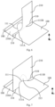
- an inflatable pool includes a bottom wall 100 and a side wall 200.
- the side wall 200 includes an inner side wall 210, an outer side wall 220, and a top wall 230.
- the outer side wall 220 surrounds the outer side of the inner side wall 210.
- Lower edges of the inner side wall 210 and the outer side wall 220 are both connected to the bottom wall 100, while upper edges of the inner side wall 210 and the outer side wall 220 are both connected to the top wall 230.
- the inner side wall 210, the outer side wall 220, the top wall 230 and the bottom wall 100 collectively define an inflatable chamber 240 of the inflatable pool.
- the bottom wall 100 and the side wall 200 together define a water cavity 300 operable to contain water, and specifically, the bottom wall 100 and the inner side wall 210 of the side wall 200 together define the water cavity 300.
- a lower edge 210A of the inner side wall 210 is welded to the bottom wall 100, forming an annular weld 110.
- the annular weld 110 has at least one arched weld segment 111 projecting toward the outer side wall 220.
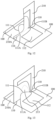
- FIG. 2 shows an example annular weld 110 and an arched weld segment 111 of an example embodiment.
- one or more portions of the annular weld 110 project toward the outer side wall 220 to form the arched weld segment(s) 111.
- the annular weld 110 may comprise at least a first and a second arched weld segment 111; other configurations may comprise more than two arched weld segments 111.
- the welds including the annular weld 110, a first weld 212, and a second weld 121, which will be mentioned below
- the arched weld segment 111 are indicated by a single dashed line in the accompanying drawings, as described herein.
- the arched weld segment 111 may be implemented at a position on the connection structure that is prone to tearing, such as a stress concentration point or a complex weld position.
- the arched weld segment 111 projects toward the outer side wall 220 with respect to other positions of the annular weld 110, so that a discrete portion of the inner side wall 210 and a correspondent portion of the bottom wall 100 placed in correspondence of the arched weld segment 111 are not connected each other along a straight line connecting two ends 111A and 111B of the arched weld segment 111, but are, at the most, in contact along this straight line, being connected each other along the arched weld segment 111.
- the inner side wall 210 extends straight towards the bottom wall 100 and then the portion both of the inner side wall 210 and of the bottom wall 100 placed right below along the generally straight line connecting the two ends 111A and 111B of the arched weld segment 111 are not welded or bonded together but are simply in contact with each other. Indeed, in correspondence of that straight line, comprised between the two ends 111A and 111B, the annular weld 110 comprised said arched weld segment 111 projecting toward the outer side wall 220.
- the annular weld 110 comprised said arched weld segment 111 projecting toward the outer side wall 220.
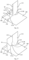
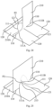
- FIGs. 8 and 9 respectively illustrate an example implementation of the formation of the structure at the arched weld segment 111 of FIG. 6 , in an upside-down configuration.
- a copper mold 400 surrounds the outside of the inner side wall 210 and a perimeter of the copper mold 400 is approximately equal to that of the inner side wall 210.
- the copper mold 400 is used in the method for welding the inner side wall 210 to the bottom wall 100 creating the annular weld 110 and the arched weld segments 111.
- the inner side wall 210 is flattened along an inside surface of the copper mold 400 and abuts against the inside surface of the copper mold 400.
- the lower edge 210A of the inner side wall 210 is then folded outward and overlaps on an upper edge of the copper mold 400, and then, the bottom wall 100 is placed over the entire lower edge 210A.
- a welding base plate of a welder is pressed against the upper edge of the copper mold 400.
- the portions of the inner side wall 210 and the bottom wall 100 sandwiched between the welding base plate and the upper edge of the copper mold 400 are welded, thus forming the annular weld 110 along the track of the upper edge of the copper mold 400.
- the arched weld segments 111 of the annular weld 110 are formed accordingly.
- the protrusions 410 shown in FIG. 8 are formed on and near the upper edge of the copper mold 400. According to one or more example embodiments, as shown in FIG. 9 , the protrusions 410 extend along the z-direction from the lower edge of the copper mold 400 to the upper edge of the copper mold 400.
- a reinforcing strip 112 may be provided at the arched weld segment 111.
- the reinforcing strip 112 connects the inner side wall 210 and the bottom wall 100 and helps to bear the pressure exerted by the water in the water cavity 300 on the arched weld segment 111.
- the reinforcing strip 112 may completely cover the arched weld segment 111, isolating the arched weld segment 111 from the water in the water cavity 300, and protecting the arched weld segment 111 from the direct hydrostatic pressure.
- the reinforcing strip 112 can be attached to the inner side wall 210 and the bottom wall 100 by bonding, welding, or other methods. It should be understood that, in some alternative embodiments, the reinforcing strip 112 may be annular and cover the entire annular weld 110, isolating the annular weld 110 from the water in the water cavity 300.
- the inner side wall 210 is formed by joining at least one inner wall splice sheet 211 end-to-end, that is, the inner side wall 210 may be formed by joining one inner wall splice sheet 211 end-to-end to create a cylindrical shape or by adjoining at least two or more inner wall splice sheets 211 together to form a big single sheet of material, which is then joined end-to-end to create a cylindrical shape. Therefore, the inner side wall 210 may comprise a first inner wall splice sheet 211 and a second inner wall splice sheet 211 placed parallel one another, having each its own entire surface overlapping the other and joined end-to-end to create a cylindrical shape.
- the lower edges 211A of the respective inner wall splice sheets 211 are also joined end-to-end so as to integrally form the lower edge 210A of the inner side wall.
- the joining method may be welding.
- a first weld 212 is formed at the joint between adjacent inner wall splice sheets 211 or end-to-end joint of the inner wall splice sheets.
- first inner wall splice sheet 211 is welded to a second end of the second inner wall splice sheet 211, thereby forming a first side wall weld which intersects the first arched weld segment 111
- a second end of the first inner wall splice sheet 211 is welded to a first end of the second inner wall splice sheet 211, thereby forming a second side wall weld which intersects the second arched weld segment 111.
- the first weld 212 may intersect the arched weld segment 111.
- first multi-layer weld point P1 the intersection of the first weld 212 and the arched weld segment 111 forms a triple-layer weld point, referred to herein as a first multi-layer weld point P1, where two layers of the inner wall splice sheets 211 and one layer of the bottom wall 100 are stacked together.
- the stress at the arched weld segment 111 is smaller than at other positions of the annular weld 110, thus reducing the risk of tearing.
- This overcomes the technical problem that is it is a straight weld segment at the position that the first weld intersects the annular weld, the connection between the inner side wall and the bottom wall at the position is weak and easily torn due to two layers of the inner side wall overlapping at the first weld.
- a reinforcing strip 112 may be provided at the arched weld segment 111.
- the reinforcing strip 112 connects the inner side wall 210 and the bottom wall 100 and helps to bear the pressure exerted by the water in the water cavity 300 on the arched weld segment 111.
- the reinforcing strip 112 may completely cover the arched weld segment 111, isolating the arched weld segment 111 from the water in the water cavity 300, and protecting the arched weld segment 111 from the direct hydrostatic pressure.
- the reinforcing strip 112 can be attached to the inner side wall 210 and the bottom wall 100 by bonding, welding, or other methods. It should be understood that, in some example embodiments, the reinforcing strip 112 is annular and covers the entire annular weld 110, isolating the annular weld 110 from the water in the water cavity 300.
- the bottom wall 100 comprises at least two bottom splice sheets 120, a first bottom splice sheet 120 and a second bottom splice sheet 120 overlapping each other; preferably, the bottom wall 100 is formed by joining at least two bottom splice sheets 120, one end of a first bottom splice sheet 120 being welded to one end of a second bottom splice sheet 120, and thus at least one second weld 121 is formed.
- the joining method may be welding.
- FIG. 2 shows an example the overlap of the second weld 121 with the arched weld segment 111, with two ends of the second weld 121 reaching the weld line between the bottom wall 100 and the outer side wall 220.
- the intersection of the second weld 121 and the arched weld segment 111 forms a triple-layer weld point, referred to herein as a second multi-layer weld point P2, where one layer of the inner side wall 210 (or the inner side wall splice sheet 211) and two layers of the bottom splice sheets 120 are stacked together.
- the stress on the annular weld 110 at the arched weld segment 111 is smaller than at other positions on the annular weld 110, thus reducing the risk of tearing.
- a reinforcing strip 112 may be provided at the arched weld segment 111.
- the reinforcing strip 112 connects the inner side wall 210 and the bottom wall 100 and helps to bear the pressure exerted by the water in the water cavity 300 on the arched weld segment 111.
- the reinforcing strip 112 may completely cover the arched weld segment 111, isolating the arched weld segment 111 from the water in the water cavity 300, and protecting the arched weld segment 111 from the direct hydrostatic pressure.
- the reinforcing strip 112 can be attached to the inner side wall 210 and the bottom wall 100 by bonding, welding, or other methods. It should be understood that, in some example embodiments, the reinforcing strip 112 may be annular and cover the entire annular weld 110, isolating the annular weld 110 from the water in the water cavity 300.
- an arched weld segment 111 may be provided to span the first and second multi-layer weld points that are close to each other to simultaneously solve the tearing problem caused by the two multi-layer weld points.
- the first and second multi-layer weld points overlap each other to form a four-layer weld point (not shown), and the arched weld segment 111 may also be provided at the four-layer weld point to reduce the risk of tearing at these weld points.
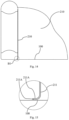
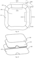
- the top wall 230 is annular and includes side bodies 230A and corner portions 230B, each side body 230A having an arcuate segment 231C curved toward the inside of the water cavity 300.
- the top wall 230 is formed by joining four top splice sheets 231 end-to-end to create the top wall 230.
- the joining method may be welding.
- Each individual top splice sheet 231 is composed of a main body section 231A and two side sections 231B at opposite ends of the main body section 231A.
- the top splice sheets 231 are connected to each other in an annular shape by joining the side sections 231B of adjacent top splice sheets 231.
- the main body section 231A of the top splice sheet 231 forms the side body 230A of the top wall 230, and the side section 231B of one top splice sheet 231 and the side section 231B of another adjacent top splice sheet 231 are welded to each other to form the corner portion 230B of the top wall 230.
- Each top splice sheet 231 has an arcuate segment 231C curved toward the inside of the water cavity 300. As shown in FIG.
- both the side body 230A and the main body section 231A have each an arcuate segment 231C curved toward the inside of the water cavity 300.
- the general area of the arcuate segment 231C is indicated by a pair of double dashed lines in FIG. 32 .
- the double dashed lines do not exist.
- Each of the side body 230A and the main body section 231A features an arcuate segment 231C curved toward the water cavity, which can increase the support force toward the water cavity 300 for the inner side wall 210 and the outer side wall 220 to resist the hydrostatic pressure in the water cavity 300.
- the arcuate segment 231C may be a part of the side body 230A/main body section 231A or may be the entire side body 230A/main body section 231A.
- all of the top splice sheets 231 of the top wall 230 may include the arcuate segment 231C curved toward the inside of the water cavity 300.
- the main body section 231A of only some of the top splice sheets 231 may include the arcuate segment 231C curved toward the inside of the water cavity 300.
- the inflatable pool shown in FIGs. 30 to 32 is substantially quadrilateral and has four top splice sheets 231.
- the shape of the inflatable pool is not limited thereto and may be any of elliptical, hexagonal, octagonal, etc.
- a number of the top splice sheets 231 may be adjusted accordingly.
- the top wall of an elliptical inflatable pool may include two semi-elliptical top splice sheets joined together
- the top wall of a hexagonal inflatable pool may include six top splice sheets joined together
- the top wall of an octagonal inflatable pool may include eight top splice sheets joined together.
- the top wall 230 may be one-piece, i.e., may be made of a single annular piece of material instead of being constructed by joining multiple splice sheets.
- tensioning members 241 are provided within the inflatable chamber 240.
- the tensioning members 241 are connected to the inner side wall 210 and the outer side wall 220, using methods such as bonding or welding, to aid in shaping during inflation of the inflatable chamber 240 and to enhance the overall structural strength of the inflatable pool while forming decorative patterns on the visible surface of the inflatable pool.
- any one or more of the inner side wall 210, the outer side wall 220, the top wall 230, and the bottom wall 100 may be made of weldable materials such as PVC (thermoplastic polyvinyl chloride), TPU (thermoplastic polyurethane), and may be bonded or welded to each other.
- the reinforcing strip 112 and the tensioning member 241 may also be made of a weldable material such as PVC or TPU, and may also be bonded or welded to the bottom wall 100, the inner side wall 210, and the outer side wall 220.
Landscapes
- Engineering & Computer Science (AREA)
- Architecture (AREA)
- Civil Engineering (AREA)
- Structural Engineering (AREA)
- Lining Or Joining Of Plastics Or The Like (AREA)
- Tents Or Canopies (AREA)
Applications Claiming Priority (1)
| Application Number | Priority Date | Filing Date | Title |
|---|---|---|---|
| CN202320761778.9U CN220133622U (zh) | 2023-04-06 | 2023-04-06 | 充气水池 |
Publications (1)
| Publication Number | Publication Date |
|---|---|
| EP4442932A1 true EP4442932A1 (de) | 2024-10-09 |
Family
ID=88413710
Family Applications (1)
| Application Number | Title | Priority Date | Filing Date |
|---|---|---|---|
| EP23203575.8A Pending EP4442932A1 (de) | 2023-04-06 | 2023-10-13 | Aufblasbares schwimmbecken |
Country Status (3)
| Country | Link |
|---|---|
| US (1) | US20240337122A1 (de) |
| EP (1) | EP4442932A1 (de) |
| CN (1) | CN220133622U (de) |
Families Citing this family (3)
| Publication number | Priority date | Publication date | Assignee | Title |
|---|---|---|---|---|
| USD1099248S1 (en) * | 2023-05-31 | 2025-10-21 | Alexander Schweid | Inflatable swimming pool with handles |
| USD1090757S1 (en) * | 2025-01-17 | 2025-08-26 | Shenzhen SenTe Cute Pet Products Co., Ltd. | Swimming pool |
| USD1102542S1 (en) * | 2025-01-17 | 2025-11-18 | Shenzhen SenTe Cute Pet Products Co., Ltd. | Swimming pool |
Citations (5)
| Publication number | Priority date | Publication date | Assignee | Title |
|---|---|---|---|---|
| US20140059760A1 (en) * | 2012-08-29 | 2014-03-06 | James Leyland Hendrick | Inflatable pool for dogs |
| US20160102470A1 (en) * | 2014-10-13 | 2016-04-14 | Harold Albert Brooks | Seamless Pool Liner and Method of Making the Same |
| CN111764707A (zh) * | 2020-08-10 | 2020-10-13 | 陶青平 | 一种方便排水的可充气泳池 |
| US20200347628A9 (en) * | 2013-07-18 | 2020-11-05 | Intex Marketing Ltd. | Inflatable spa |
| CN216866153U (zh) * | 2021-12-16 | 2022-07-01 | 江苏吉龙运动休闲用品有限公司 | 一种充气水池 |
Family Cites Families (23)
| Publication number | Priority date | Publication date | Assignee | Title |
|---|---|---|---|---|
| NL167854C (nl) * | 1976-10-27 | 1982-02-16 | Ratelband Johannes B | Zweminrichting. |
| FR2461792A1 (fr) * | 1979-07-18 | 1981-02-06 | Zodiac | Perfectionnements apportes aux reservoirs d'eau, notamment aux piscines |
| US4597113A (en) * | 1985-03-21 | 1986-07-01 | Zodiac | Inflatable reservoir for containing a liquid, more especially an inflatable swimming pool, and a method for filling same |
| US4935970A (en) * | 1989-04-11 | 1990-06-26 | Barbara Aristone | Child's pool |
| US5924144A (en) * | 1998-04-02 | 1999-07-20 | Sportsstuff, Inc. | Inflatable swimming pool and supporting shell |
| US5987661A (en) * | 1998-06-25 | 1999-11-23 | Sportsstuff, Inc. | Inflatable swimming pool and supporting net |
| US6062983A (en) * | 1999-07-01 | 2000-05-16 | Butsook; Peter | Combination water slide and pool |
| US6595861B1 (en) * | 2002-01-29 | 2003-07-22 | Sandra L Morrow | Infant play pool |
| US7699186B2 (en) * | 2003-01-17 | 2010-04-20 | Patent Category Corp. | Collapsible structures |
| US7308989B2 (en) * | 2003-01-17 | 2007-12-18 | Patent Category Corp. | Collapsible structures |
| US20050159275A1 (en) * | 2003-12-24 | 2005-07-21 | Bullman Barbara E. | Complete and portable aquatic exercise system called: "The Hydro Jogger"™ |
| US7218235B1 (en) * | 2004-09-30 | 2007-05-15 | Rainey Jeffrey L | Motion responsive swimming pool safety device |
| FR2896997B1 (fr) * | 2006-02-07 | 2011-11-04 | Christophe Mayaud | Dispositif amovible permettant la nage stationnaire dans une piscine hors sol. |
| US20220325546A1 (en) * | 2013-07-18 | 2022-10-13 | Intex Marketing Ltd. | Inflatable spa |
| PL3077606T3 (pl) * | 2013-12-05 | 2019-09-30 | Intex Recreation Corp. | Basen dmuchany |
| CN207568250U (zh) * | 2017-11-24 | 2018-07-03 | 上海荣威塑胶工业有限公司 | 一种充气水池 |
| CN111576946B (zh) * | 2020-05-26 | 2025-02-25 | 江苏吉龙运动休闲用品有限公司 | 一种充气水池及其制作方法 |
| CN213269138U (zh) * | 2020-09-09 | 2021-05-25 | 南通荣威娱乐用品有限公司 | 用于充气水池的管道组件以及充气水池 |
| CN214463007U (zh) * | 2021-02-09 | 2021-10-22 | 上海荣威塑胶工业有限公司 | 充气水池 |
| CN214996405U (zh) * | 2021-07-12 | 2021-12-03 | 上海荣威塑胶工业有限公司 | 按摩充气水池 |
| US12540481B2 (en) * | 2022-07-04 | 2026-02-03 | Bestway Inflatables & Material Corp. | Pool having built-in seat |
| CN220725888U (zh) * | 2023-02-24 | 2024-04-05 | 上海荣威塑胶工业有限公司 | 具有保温结构的充气水池 |
| CN221524384U (zh) * | 2023-09-19 | 2024-08-13 | 上海荣威塑胶工业有限公司 | 一种充气水池 |
-
2023
- 2023-04-06 CN CN202320761778.9U patent/CN220133622U/zh active Active
- 2023-09-08 US US18/243,895 patent/US20240337122A1/en active Pending
- 2023-10-13 EP EP23203575.8A patent/EP4442932A1/de active Pending
Patent Citations (5)
| Publication number | Priority date | Publication date | Assignee | Title |
|---|---|---|---|---|
| US20140059760A1 (en) * | 2012-08-29 | 2014-03-06 | James Leyland Hendrick | Inflatable pool for dogs |
| US20200347628A9 (en) * | 2013-07-18 | 2020-11-05 | Intex Marketing Ltd. | Inflatable spa |
| US20160102470A1 (en) * | 2014-10-13 | 2016-04-14 | Harold Albert Brooks | Seamless Pool Liner and Method of Making the Same |
| CN111764707A (zh) * | 2020-08-10 | 2020-10-13 | 陶青平 | 一种方便排水的可充气泳池 |
| CN216866153U (zh) * | 2021-12-16 | 2022-07-01 | 江苏吉龙运动休闲用品有限公司 | 一种充气水池 |
Also Published As
| Publication number | Publication date |
|---|---|
| US20240337122A1 (en) | 2024-10-10 |
| CN220133622U (zh) | 2023-12-05 |
Similar Documents
| Publication | Publication Date | Title |
|---|---|---|
| EP4442932A1 (de) | Aufblasbares schwimmbecken | |
| JPS6119719Y2 (de) | ||
| US4547919A (en) | Inflatable article with reforming and reinforcing structure | |
| US5096529A (en) | Adjustable seat assembly bladder sealing method | |
| JPH0872649A (ja) | エアバッグ | |
| US20080105366A1 (en) | Method for producing plastic products with reinforced heat sealed joints | |
| US7306694B2 (en) | Method for producing plastic products with reinforced heat sealed joints | |
| EP3524099B1 (de) | Aufblasbares produkt | |
| CA2592946A1 (en) | Partition assembly made with multiple ply partitions | |
| US4756032A (en) | Inflatable pool | |
| JP2009196610A (ja) | 内装部品縫製部構造 | |
| US11969097B2 (en) | Inflatable product | |
| US5031260A (en) | Fluid-filled mattress construction | |
| JPH07196080A (ja) | 膨張式の浮揚筏装置及びその組み立て方法 | |
| US5137592A (en) | Fluid-filled mattress construction | |
| US4520054A (en) | Flexible hollow body fillable with fluid medium | |
| US4914761A (en) | Reinforced corner for waterbed mattress | |
| EP0630219B1 (de) | Sammelbeutel sowie verfahren zum herstellen solcher beutel | |
| US6432495B1 (en) | Abrasion resistant air bag | |
| US6322870B1 (en) | Sheet material sealing structure for inflatable apparatus | |
| CN220764643U (zh) | 一种漂浮装置 | |
| JPH06329143A (ja) | 断熱複合容器材料及び該材料からなる容器 | |
| US20240335050A1 (en) | Inflatable product | |
| JP6248007B2 (ja) | 連結ふうせん | |
| CN222285924U (zh) | 一种气袋、气动按摩系统及按摩座椅 |
Legal Events
| Date | Code | Title | Description |
|---|---|---|---|
| PUAI | Public reference made under article 153(3) epc to a published international application that has entered the european phase |
Free format text: ORIGINAL CODE: 0009012 |
|
| STAA | Information on the status of an ep patent application or granted ep patent |
Free format text: STATUS: THE APPLICATION HAS BEEN PUBLISHED |
|
| AK | Designated contracting states |
Kind code of ref document: A1 Designated state(s): AL AT BE BG CH CY CZ DE DK EE ES FI FR GB GR HR HU IE IS IT LI LT LU LV MC ME MK MT NL NO PL PT RO RS SE SI SK SM TR |
|
| STAA | Information on the status of an ep patent application or granted ep patent |
Free format text: STATUS: REQUEST FOR EXAMINATION WAS MADE |
|
| 17P | Request for examination filed |
Effective date: 20250402 |