EP4450596A1 - Procédé de pyrolyse d'une matière plastique - Google Patents
Procédé de pyrolyse d'une matière plastique Download PDFInfo
- Publication number
- EP4450596A1 EP4450596A1 EP23168533.0A EP23168533A EP4450596A1 EP 4450596 A1 EP4450596 A1 EP 4450596A1 EP 23168533 A EP23168533 A EP 23168533A EP 4450596 A1 EP4450596 A1 EP 4450596A1
- Authority
- EP
- European Patent Office
- Prior art keywords
- pyrolysis
- plastic
- separation
- fraction
- solids
- Prior art date
- Legal status (The legal status is an assumption and is not a legal conclusion. Google has not performed a legal analysis and makes no representation as to the accuracy of the status listed.)
- Withdrawn
Links
Images
Classifications
-
- C—CHEMISTRY; METALLURGY
- C10—PETROLEUM, GAS OR COKE INDUSTRIES; TECHNICAL GASES CONTAINING CARBON MONOXIDE; FUELS; LUBRICANTS; PEAT
- C10G—CRACKING HYDROCARBON OILS; PRODUCTION OF LIQUID HYDROCARBON MIXTURES, e.g. BY DESTRUCTIVE HYDROGENATION, OLIGOMERISATION, POLYMERISATION; RECOVERY OF HYDROCARBON OILS FROM OIL-SHALE, OIL-SAND, OR GASES; REFINING MIXTURES MAINLY CONSISTING OF HYDROCARBONS; REFORMING OF NAPHTHA; MINERAL WAXES
- C10G1/00—Production of liquid hydrocarbon mixtures from oil-shale, oil-sand, or non-melting solid carbonaceous or similar materials, e.g. wood, coal
- C10G1/10—Production of liquid hydrocarbon mixtures from oil-shale, oil-sand, or non-melting solid carbonaceous or similar materials, e.g. wood, coal from rubber or rubber waste
-
- C—CHEMISTRY; METALLURGY
- C10—PETROLEUM, GAS OR COKE INDUSTRIES; TECHNICAL GASES CONTAINING CARBON MONOXIDE; FUELS; LUBRICANTS; PEAT
- C10G—CRACKING HYDROCARBON OILS; PRODUCTION OF LIQUID HYDROCARBON MIXTURES, e.g. BY DESTRUCTIVE HYDROGENATION, OLIGOMERISATION, POLYMERISATION; RECOVERY OF HYDROCARBON OILS FROM OIL-SHALE, OIL-SAND, OR GASES; REFINING MIXTURES MAINLY CONSISTING OF HYDROCARBONS; REFORMING OF NAPHTHA; MINERAL WAXES
- C10G1/00—Production of liquid hydrocarbon mixtures from oil-shale, oil-sand, or non-melting solid carbonaceous or similar materials, e.g. wood, coal
- C10G1/002—Production of liquid hydrocarbon mixtures from oil-shale, oil-sand, or non-melting solid carbonaceous or similar materials, e.g. wood, coal in combination with oil conversion- or refining processes
-
- C—CHEMISTRY; METALLURGY
- C10—PETROLEUM, GAS OR COKE INDUSTRIES; TECHNICAL GASES CONTAINING CARBON MONOXIDE; FUELS; LUBRICANTS; PEAT
- C10G—CRACKING HYDROCARBON OILS; PRODUCTION OF LIQUID HYDROCARBON MIXTURES, e.g. BY DESTRUCTIVE HYDROGENATION, OLIGOMERISATION, POLYMERISATION; RECOVERY OF HYDROCARBON OILS FROM OIL-SHALE, OIL-SAND, OR GASES; REFINING MIXTURES MAINLY CONSISTING OF HYDROCARBONS; REFORMING OF NAPHTHA; MINERAL WAXES
- C10G31/00—Refining of hydrocarbon oils, in the absence of hydrogen, by methods not otherwise provided for
- C10G31/09—Refining of hydrocarbon oils, in the absence of hydrogen, by methods not otherwise provided for by filtration
-
- C—CHEMISTRY; METALLURGY
- C10—PETROLEUM, GAS OR COKE INDUSTRIES; TECHNICAL GASES CONTAINING CARBON MONOXIDE; FUELS; LUBRICANTS; PEAT
- C10G—CRACKING HYDROCARBON OILS; PRODUCTION OF LIQUID HYDROCARBON MIXTURES, e.g. BY DESTRUCTIVE HYDROGENATION, OLIGOMERISATION, POLYMERISATION; RECOVERY OF HYDROCARBON OILS FROM OIL-SHALE, OIL-SAND, OR GASES; REFINING MIXTURES MAINLY CONSISTING OF HYDROCARBONS; REFORMING OF NAPHTHA; MINERAL WAXES
- C10G31/00—Refining of hydrocarbon oils, in the absence of hydrogen, by methods not otherwise provided for
- C10G31/10—Refining of hydrocarbon oils, in the absence of hydrogen, by methods not otherwise provided for with the aid of centrifugal force
-
- Y—GENERAL TAGGING OF NEW TECHNOLOGICAL DEVELOPMENTS; GENERAL TAGGING OF CROSS-SECTIONAL TECHNOLOGIES SPANNING OVER SEVERAL SECTIONS OF THE IPC; TECHNICAL SUBJECTS COVERED BY FORMER USPC CROSS-REFERENCE ART COLLECTIONS [XRACs] AND DIGESTS
- Y02—TECHNOLOGIES OR APPLICATIONS FOR MITIGATION OR ADAPTATION AGAINST CLIMATE CHANGE
- Y02P—CLIMATE CHANGE MITIGATION TECHNOLOGIES IN THE PRODUCTION OR PROCESSING OF GOODS
- Y02P20/00—Technologies relating to chemical industry
- Y02P20/141—Feedstock
- Y02P20/143—Feedstock the feedstock being recycled material, e.g. plastics
Definitions
- the invention relates to a method and a device for the pyrolysis of a plastic, in particular a waste plastic.
- Methods for pyrolyzing a starting material, in particular a plastic are known in the prior art. The focus is on separating a gaseous fraction from a pyrolysis product, while the rest of the pyrolysis product, in particular a solids-rich fraction, is typically used for energy purposes.
- the EP 1 154 007 A1 discloses a method for pyrolysis of a waste plastic.
- the waste plastic is pyrolyzed in a first pyrolysis reactor at a first temperature, whereby a first pyrolysis product comprising a first gaseous fraction and a first pyrolysis residue is obtained.
- the first pyrolysis residue is then pyrolyzed in a second pyrolysis reactor at a second temperature, which is higher than the first temperature, whereby a second pyrolysis product comprising a second gaseous fraction and a second pyrolysis residue is obtained.
- the second pyrolysis residue is subjected to a magnetic separation process in order to obtain inorganic fillers and waste metals.
- waste plastic is converted in a pyrolysis reactor into a pyrolysis product comprising a gaseous fraction and a solid pyrolysis residue.
- the pyrolysis residue is then separated in a separation unit, such as a cyclone, into a low-solids fraction and a high-solids fraction.
- the low-solids fraction is returned to the pyrolysis reactor for further pyrolysis.
- the high-solids fraction is separated in a settling tank based on its density. A first part of the low-solids fraction is returned to the pyrolysis reactor together with the low-solids fraction, while a second part of the high-solids fraction can be used as a high-energy fuel.
- the pyrolysis product can be at least be partially recycled.
- This method and device enable particularly good processing of the first and second pyrolysis residues by carrying out two pyrolysis steps in two different pyrolysis reactors and separating the pyrolysis residue between the two pyrolysis steps into a low-solids fraction and a high-solids fraction. Pyrolysis product and separation into individual components, which enables a high degree of recycling. The process can therefore reduce the burden on the environment, as greenhouse gas emissions can be lowered and the amount of waste can be reduced. Overall, resource consumption can be significantly reduced and the circular economy can be strengthened, which can also bring economic benefits.
- the plastic preferably comprises a polyolefin and/or a polystyrene (PS), whereby the polyolefin can comprise a polyethylene (PE) and/or a polypropylene (PP).
- PS polystyrene
- the plastic preferably comprises the polyolefin and/or the polystyrene in an amount of at least 65% by weight, more preferably at least 70% by weight, in particular at least 90% by weight, based on the total weight of the plastic. This makes it possible to obtain a pyrolysis residue which comprises a significant proportion of an aliphatic hydrocarbon (or a mixture of several aliphatic hydrocarbons).
- the plastic preferably comprises at least 20% by weight of the polyolefin, more preferably at least 50% by weight, even more preferably at least 70% by weight, in particular at least 90% by weight, based on the total weight of the plastic.
- the plastic can comprise a further polymer from the group consisting of thermoplastics, thermosets and/or elastomers, in particular an acrylonitrile-butadiene-styrene copolymer (ABS), a polyvinyl chloride (PVC), a polyamide (PA) and/or a polyester.
- the plastic Before step (a) of the process, the plastic can be plasticized, for example in a mixer, in particular in an extruder.
- the plastic is preferably heated to a temperature of at least 120 °C in order to plasticize it, more preferably to a temperature of 200 to 500 °C, even more preferably 400 to 470 °C.
- the subsequent pyrolysis can then be carried out more energy efficiently and in a shorter time.
- the plastic in the extruder, can also be degassed to produce a uniform mass without gas inclusions, so that the subsequent pyrolysis a homogeneous pyrolysis product can be obtained.
- a diluent can be added to the plastic, in particular the plasticized plastic, to reduce the viscosity.
- the device can have an introduction device which is set up to add a diluent to the plastic to reduce the viscosity before pyrolysis in the first pyrolysis reactor.
- the diluent is preferably added to the plastic in an amount of at least 5% by weight, more preferably at least 9% by weight, based on the total weight of the plastic.
- the ratio of plastic to diluent is preferably at least 1:4, preferably at least 1:9.
- the mobility of polymer chains can be increased at a given temperature, so that the heat input into the plastic can be improved during pyrolysis. Furthermore, due to the reduction in viscosity, the risk of overheating of plastic in wall areas of the pyrolysis reactor can be reduced, since it is usually heated by a heating device arranged near an outer wall of the pyrolysis reactor. The risk of coking of the plastic during pyrolysis can also be reduced by reducing the viscosity.
- its viscosity can preferably be reduced by at least 30%, more preferably by at least 50%, particularly preferably by at least 80%, based on the viscosity of the plastic without diluent under the same measuring conditions, in particular at a temperature in the range of 180 to 240 °C. This can improve the pumpability of the plastic, which can facilitate its processing.
- the plastic When the diluent is added, the plastic preferably has a temperature of at least 120 °C, more preferably a temperature of 150 to 300 °C, in particular of 200 to 300 °C.
- the diluent can be heated to a temperature of preferably at least 120 °C, more preferably at least 150 °C, in particular to a temperature of 200 to 300 °C before being added to the plastic.
- the diluent can be mixed into the plastic more quickly and efficiently. The subsequent pyrolysis can also be carried out more energy efficiently and more quickly.
- the diluent can be added to the plastic using a adding device.
- the adding device can have a metering device, such as a metering pump.
- the plastic in particular the plasticized plastic, can be fed to a mixer, e.g. a static mixer, and mixed there with the diluent.
- the diluent can be added directly in the extruder.
- the adding device can be arranged, for example, in the compression zone or mixing zone of the extruder.
- the diluent can comprise a hydrocarbon selected from an alkane, a cycloalkane and/or an aromatic. Pyrolysis can convert such a diluent into a gaseous and/or liquid product, which can be at least partially separated from the pyrolysis residue and reused.
- the diluent can comprise a fraction obtained from crude oil, preferably a heavy oil.
- the heavy oil can be an oil obtained from crude oil in a petroleum refinery, e.g. a residual oil from a pyrolysis plant.
- the heavy oil preferably has a proportion of an aromatic hydrocarbon of at least 25% by weight, based on the total weight of the heavy oil.
- the diluent may comprise part of the liquid fraction of the first pyrolysis product and/or part of the low-solids fraction. This may enable reuse of the liquid fraction and the low-solids fraction.
- the diluent consists of at least part of the liquid fraction of the first pyrolysis product and/or at least part of the low-solids fraction. A high degree of recycling can then be achieved.
- the diluent preferably has a boiling point (or a lower end of a boiling range) of at least 300 °C, in particular at least 350 °C. This can avoid It is not possible for the diluent to evaporate immediately after a mixture of plastic and diluent is introduced into the pyrolysis reactor, but rather evaporation, splitting and/or depolymerization of the diluent can only take place as the mixture spends more time in the pyrolysis reactor and the mixture heats up as a result. This makes it possible to obtain a homogeneous pyrolysis product.
- the plastic is pyrolyzed in a first pyrolysis reactor.
- the first pyrolysis reactor can be a screw reactor, a fluidized bed reactor, a rotary tube reactor or a coker, preferably a coker.
- the temperature in the first pyrolysis reactor is preferably in the range from 300 to 800 °C, more preferably from 350 to 700 °C.
- the pressure in the first pyrolysis reactor in step (a) is preferably in the range from 1 to 30 bar, more preferably from 5 to 30 bar, even more preferably 10 to 25 bar.
- pyrolysis is preferably carried out for a period of 0.3 min, more preferably for a period of 1 to 10 min, in particular 1.5 to 5 min. This makes it possible to achieve a good balance between economic viability and process efficiency.
- the pyrolysis in step (a) may be thermal pyrolysis (i.e. thermal cracking without addition of a catalyst) and/or catalytic pyrolysis (i.e. catalytic cracking).
- Thermal pyrolysis is preferred to avoid any contamination of the wax and/or the solid due to catalyst components.
- the pyrolysis in step (a) can be carried out largely in the absence of oxygen, in particular in an inert atmosphere, for example under nitrogen.
- a lack of oxygen or the absence of oxygen can prevent complete combustion and a polymer contained in the plastic can be split or depolymerized.
- the first pyrolysis product comprises a pyrolysis residue. Furthermore, the first pyrolysis product comprises a liquid fraction and/or a gaseous fraction.
- the pyrolysis residue is separated from the first pyrolysis product in a first separation unit.
- the separation can be carried out by Evaporation and/or centrifugal separation (ie centrifugation) can take place, preferably by centrifugal separation.
- the first separation unit can have an evaporator, a cyclone and/or a hydrocyclone, in particular a hydrocyclone.
- the temperature in the first separation unit in step (b) is preferably in the range from 300 to 700 °C, more preferably in the range from 330 to 420 °C.
- the pressure in the first separation unit in step (b) is preferably in the range from 1 to 15 bar, more preferably in the range from 2 to 8 bar.
- the first separation unit preferably has a hydrocyclone with which the gaseous fraction, the liquid fraction and the pyrolysis residue can be separated from one another in just one process step.
- a hydrocyclone is described in the application WO 2023/036751 A1 described.
- the remaining part of the first pyrolysis product can then be discharged due to gravity in the direction of a bottom of the hydrocyclone, wherein a tangential speed of a developing vortex flow can continuously increase.
- at least part of the pyrolysis residue can be discharged via an outlet arranged in the bottom of the hydrocyclone, while at least part of a liquid fraction of the first pyrolysis product can reach an inner container arranged in the hydrocyclone and can be discharged from there via an outlet.
- This part of the liquid fraction can then be used as a diluent to reduce the viscosity of the plastic before step (a) of the process.
- the pyrolysis residue discharged via the outlet arranged in the bottom of the hydrocyclone can then be used in step (c) of the process.
- the hydrocyclone is preferably operated at a temperature in the range of 300 to 450 °C, more preferably from 320 to 420 °C, especially preferably from 360 to 400 °C.
- the pyrolysis residue separated in step (b) of the process preferably has a boiling temperature (or a lower end of a boiling range) of at least 250 °C, more preferably at least 300 °C, even more preferably at least 330 °C, particularly preferably at least 350 °C.
- the boiling temperature (or boiling range) of the pyrolysis residue can be determined by means of the standard ASTM D7500-15:2019 (preferably when the pyrolysis residue has a boiling temperature or boiling range of 100 to 850 °C, in particular 100 to 735 °C) or by means of the standard ASTM D2887-22:2022 (preferably when the pyrolysis residue has a boiling temperature or boiling range of 55 to 538 °C).
- the pyrolysis residue separated in step (b) of the process preferably comprises a carbon fraction having at least 14 carbon atoms per molecule, more preferably at least 16 carbon atoms per molecule, particularly preferably at least 18 carbon atoms per molecule.
- the pyrolysis residue can then be readily separated in the subsequent step (c) of the process.
- the pyrolysis residue is separated in a second separation unit into a low-solids fraction and a high-solids fraction.
- the low-solids fraction preferably has a liquid content of more than 70 wt. %, preferably more than 80 wt. %, more preferably more than 85 wt. %, more preferably more than 90 wt. %, more preferably more than 95 wt. %, more preferably more than 98 wt. %, more preferably more than 99 wt.
- the low-solids fraction has a liquid content in the range from 80 to 100 wt. %, more preferably 90 to 99.9 wt.
- the low-solids fraction preferably has a density at 20 °C and 101325 Pa in the range from 0.600 to 1.100 g/cm 3 , more preferably 0.750 to 0.990 g/cm 3 .
- the solids-rich fraction preferably has a liquid content of less than 95% by weight, preferably less than 90% by weight, more preferably less than 85% by weight, more preferably less than 80% by weight, more preferably less than 75% by weight, more preferably less than 70% by weight.
- the solids-rich fraction has a liquid content in the range of 50 to 95% by weight, more preferably 70 to 90% by weight, based on the total weight of the solids-rich fraction.
- the solids-rich fraction preferably has a density at 20 °C and 101325 Pa in the range from 0.650 to 1.300 g/cm 3 , more preferably 0.800 to 1.150 g/cm 3 .
- the solids-rich fraction preferably has a lower liquid content than the solids-poor fraction. It is also preferred if the solids-rich fraction has a higher density at 20 °C and 101325 Pa than the solids-poor fraction.
- the separation in the second separation unit can comprise gravimetric separation, filtration and/or centrifugal separation, preferably centrifugal separation.
- the gravimetric separation can comprise sedimentation and/or decanting.
- the second separation unit can comprise a device for gravimetric separation, a filter, a centrifuge and/or a hydrocyclone, preferably a hydrocyclone.
- the device for gravimetric separation can comprise a sedimentation system and/or a decanter. If the second separation unit comprises a hydrocyclone, this can be constructed and operated in the same or similar manner as the hydrocyclone of the first separation unit, as described above.
- the separation in the second separation unit in step (c) comprises centrifugal separation in combination with filtration or gravimetric separation.
- the centrifugal separation can take place before the filtration or before the gravimetric separation.
- the second separation unit can have the hydrocyclone in combination with the filter or the device for gravimetric separation.
- the hydrocyclone can be installed upstream of the filter or the device for gravimetric separation. In this way, a sharp separation into the low-solids fraction and the high-solids fraction can take place.
- the temperature in the second separation unit in step (c) is preferably in the range of 100 to 700 °C, more preferably 100 to 350 °C, even more preferably 100 to 200 °C.
- the temperature is preferably in the range of 180 to 700 °C.
- the temperature is preferably 200 °C or below, more preferably in the range of 100 to 180 °C.
- the temperature is preferably in the range of 200 to 700 °C. If the temperature is selected as indicated depending on the process, the separation into a low-solids fraction and a high-solids fraction can proceed efficiently.
- step (d) of the process the solids-rich fraction is pyrolyzed in a second pyrolysis reactor to obtain a second pyrolysis product.
- the second pyrolysis reactor may be a screw reactor, a fluidized bed reactor, a rotary tube reactor or a coker, preferably a coker.
- the temperature in the second pyrolysis reactor is preferably in the range of 400 to 800 °C, more preferably in the range of 500 to 700 °C. This allows the solids-rich fraction to be efficiently pyrolyzed.
- the temperature during pyrolysis in the second pyrolysis reactor in step (d) can be higher than the temperature during pyrolysis in the first pyrolysis reactor in step (a).
- the temperature in the second pyrolysis reactor is preferably at least 50 °C higher than the temperature in the first pyrolysis reactor, more preferably at least 80 °C, even more preferably at least 100 °C, even more preferably at least 150 °C, in particular at least 200 °C.
- the pressure in the second pyrolysis reactor is preferably in the range from 1 to 20 bar, more preferably in the range from 2 to 12 bar, in particular 2 to 8 bar.
- pyrolysis is preferably carried out for a period of 1 to 90 minutes, in particular 1.5 to 5 minutes. This makes it possible to achieve a good balance between economic viability and process efficiency.
- a ratio of the volumetric capacity of the first pyrolysis reactor and the second pyrolysis reactor is a maximum of 10:3, more preferably a maximum of 10:2, preferably in the range from 10:0.2 to 10:2, in particular from 10:1 to 10:2.
- the volumetric capacity is understood to mean the maximum possible filling level of the respective pyrolysis reactor.
- the second pyrolysis product may comprise a solid, a gas and/or a liquid.
- the amount of gas is preferably at least 10 % by weight, more preferably at least 20 % by weight, even more preferably at least 40 % by weight, based on the total weight of the second pyrolysis product.
- the gas preferably comprises a proportion of a carbon fraction of at least 5 % by weight, more preferably at least 15 % by weight, even more preferably at least 20 % by weight, in particular at least 40 % by weight, based on the total weight of the gas.
- the carbon fraction of the gas preferably comprises methane, ethane, ethene, propane, propene, butane, butene, butadiene or a mixture of these components. These components of the gas can be separated from one another, for example by fractional distillation, in order to supply them for further use, for example in other plants of a refinery.
- the liquid preferably comprises an oil, whereby the oil can comprise a light oil and a heavy oil.
- the light oil can comprise a carbon fraction of 3 to 14 carbon atoms per molecule
- the heavy oil can comprise a carbon fraction of 11 to 50 carbon atoms per molecule.
- the amount of solid is preferably a maximum of 70% by weight, more preferably a maximum of 55% by weight, even more preferably a maximum of 30% by weight, based on the total weight of the second pyrolysis product.
- the solid can comprise an inorganic salt, a ceramic raw material, an asphaltene, a tar and/or a coke.
- the solid can comprise talc, an iron oxide (e.g. iron(III) oxide), aluminum oxide, titanium dioxide, magnesium oxide and/or calcium carbonate.
- the pyrolysis residue provided is obtained by pyrolyzing a plastic, the solid can comprise an additive contained in the plastic.
- the additive can comprise a filler, a color pigment and/or an additive. A person skilled in the art knows which additives are used depending on the respective plastic and field of application.
- the method may comprise a further step (e): separating at least part of the solid from the second pyrolysis product.
- the device may have a solid separation device.
- the separation of the solid from the second pyrolysis product can comprise gravimetric separation, filtration and/or centrifugal separation, preferably filtration.
- the gravimetric separation can comprise sedimentation and/or decanting. If the separation comprises filtration, this can be carried out using a filter medium which can comprise activated carbon or bleaching earth. This allows any polar components (e.g. a tar or a polyphenol) dissolved together with the wax in the solvent to be separated and adsorbed by the filter medium.
- a filter medium which can comprise activated carbon or bleaching earth. This allows any polar components (e.g. a tar or a polyphenol) dissolved together with the wax in the solvent to be separated and adsorbed by the filter medium.
- D50 average particle size
- the separation of the solid from the second pyrolysis product can also take place directly in the second pyrolysis reactor.
- the second pyrolysis reactor is preferably a screw reactor for this purpose.
- the solid can be discharged directly from the extruder by means of a discharge device.
- the solid After it has been separated from the second pyrolysis product, i.e. after step (e) of the process, the solid can be dried, for example in an oven. This makes the solid free-flowing and thus easier to process.
- the solid is preferably dried at a temperature in the range from 50 to 250 °C, more preferably from 100 to 200 °C, even more preferably from 130 to 160 °C.
- the drying time is preferably up to 120 minutes, in particular from 5 to 60 minutes.
- One or more components can be separated from the solid, in particular from the dried solid, and then reused, e.g. as an additive for a plastic.
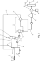
- Fig. 1 shows a flow chart of a process for the pyrolysis of a plastic.
- a plastic comprising at least 50% by weight of a polyolefin is fed to an extruder 1 in which the plastic is plasticized and degassed.
- the plasticized plastic has a temperature of at least 120 °C and is then added to a static mixer 2.
- a diluent 3 can be added to the plasticized plastic in order to reduce its viscosity.
- a part of a liquid fraction 4 separated from the first pyrolysis product 6 can be mixed with the plasticized plastic in order to reduce its viscosity.
- the resulting mixture is then fed to a first pyrolysis reactor 5 in which the plastic is pyrolyzed at a temperature of 350 to 700 °C.
- a first pyrolysis product 6 comprising a gaseous fraction, a liquid fraction and a pyrolysis residue.
- the first pyrolysis product 6 is fed to a first separation unit 7 which is connected downstream of the first pyrolysis reactor 5 and has a hydrocyclone.
- the gaseous fraction is at least partially separated in the hydrocyclone.
- the separated part of the gaseous fraction 8 can then be further separated into a light oil (e.g. with a boiling range of 35 to 225 °C) and a heavy oil (e.g.
- the liquid fraction is at least partially separated in the hydrocyclone.
- the separated part of the liquid fraction 4 can be discharged via an outlet 9 of the hydrocyclone and reused in the process for reducing the viscosity of the plastic, as described above.
- At least part of the pyrolysis residue, which at least partially comprises the pyrolysis residue, is discharged via an outlet 10 arranged in the bottom of the hydrocyclone.
- the pyrolysis residue discharged via the outlet 10 is fed to a second separation unit 11, which has a hydrocyclone 12 and a filter 13, where it is separated into a low-solids fraction 14 and a high-solids fraction 15.
- the low-solids fraction has a liquid content in the range of 80 to 100 wt.%, based on the total weight of the low-solids fraction
- the high-solids fraction has a liquid content in the range of 50 to 95 wt.%, based on the total weight of the high-solids fraction.
- the low-solids fraction 14 can be reused in the process by adding at least part of the low-solids fraction 14 to the plasticized plastic in the mixer 2 to reduce the viscosity.
Landscapes
- Chemical & Material Sciences (AREA)
- Oil, Petroleum & Natural Gas (AREA)
- Engineering & Computer Science (AREA)
- Chemical Kinetics & Catalysis (AREA)
- General Chemical & Material Sciences (AREA)
- Organic Chemistry (AREA)
- Life Sciences & Earth Sciences (AREA)
- Wood Science & Technology (AREA)
- Production Of Liquid Hydrocarbon Mixture For Refining Petroleum (AREA)
- Separation, Recovery Or Treatment Of Waste Materials Containing Plastics (AREA)
- Organic Low-Molecular-Weight Compounds And Preparation Thereof (AREA)
Priority Applications (6)
| Application Number | Priority Date | Filing Date | Title |
|---|---|---|---|
| EP23168533.0A EP4450596A1 (fr) | 2023-04-18 | 2023-04-18 | Procédé de pyrolyse d'une matière plastique |
| PCT/EP2024/060472 WO2024218181A1 (fr) | 2023-04-18 | 2024-04-18 | Procédé de pyrolyse d'un plastique |
| KR1020257036542A KR20260004352A (ko) | 2023-04-18 | 2024-04-18 | 플라스틱 열분해 방법 |
| EP24719550.6A EP4698612A1 (fr) | 2023-04-18 | 2024-04-18 | Procédé de pyrolyse d'un plastique |
| CN202480022866.4A CN121039254A (zh) | 2023-04-18 | 2024-04-18 | 用于热解塑料的方法 |
| MX2025010797A MX2025010797A (es) | 2023-04-18 | 2025-09-12 | Metodo para la pirolisis de un plastico |
Applications Claiming Priority (1)
| Application Number | Priority Date | Filing Date | Title |
|---|---|---|---|
| EP23168533.0A EP4450596A1 (fr) | 2023-04-18 | 2023-04-18 | Procédé de pyrolyse d'une matière plastique |
Publications (1)
| Publication Number | Publication Date |
|---|---|
| EP4450596A1 true EP4450596A1 (fr) | 2024-10-23 |
Family
ID=86053735
Family Applications (2)
| Application Number | Title | Priority Date | Filing Date |
|---|---|---|---|
| EP23168533.0A Withdrawn EP4450596A1 (fr) | 2023-04-18 | 2023-04-18 | Procédé de pyrolyse d'une matière plastique |
| EP24719550.6A Pending EP4698612A1 (fr) | 2023-04-18 | 2024-04-18 | Procédé de pyrolyse d'un plastique |
Family Applications After (1)
| Application Number | Title | Priority Date | Filing Date |
|---|---|---|---|
| EP24719550.6A Pending EP4698612A1 (fr) | 2023-04-18 | 2024-04-18 | Procédé de pyrolyse d'un plastique |
Country Status (5)
| Country | Link |
|---|---|
| EP (2) | EP4450596A1 (fr) |
| KR (1) | KR20260004352A (fr) |
| CN (1) | CN121039254A (fr) |
| MX (1) | MX2025010797A (fr) |
| WO (1) | WO2024218181A1 (fr) |
Citations (7)
| Publication number | Priority date | Publication date | Assignee | Title |
|---|---|---|---|---|
| EP1154007A1 (fr) | 1998-09-24 | 2001-11-14 | Dingli Zhou | Procede et appareil de production d'hydrocarbures a partir de dechets urbains et/ou de dechets organiques |
| US20120117860A1 (en) * | 2010-11-16 | 2012-05-17 | Kior, Inc. | Two-Stage Reactor and Process for Conversion of Solid Biomass Material |
| WO2016116114A1 (fr) | 2015-01-19 | 2016-07-28 | VAN DER REE, Teunis Christiaan | Procédé et installation pour la transformation des déchets de matières plastiques en un combustible ayant les propriétés du diesel/du fioul |
| WO2017168163A1 (fr) * | 2016-03-31 | 2017-10-05 | Trifol Resources Limited | Procédé de préparation d'une cire en c20 à c60 à partir de la décomposition thermique sélective d'un polymère de polyoléfine plastique |
| US20220340819A1 (en) * | 2021-04-27 | 2022-10-27 | Uop Llc | Plastics pyrolysis process with quench |
| WO2023036751A1 (fr) | 2021-09-07 | 2023-03-16 | OMV Downstream GmbH | Appareil et procédé de séparation de composants d'un flux d'hydrocarbures multiphasique |
| EP4151702A1 (fr) * | 2021-09-17 | 2023-03-22 | Alpha Trading S.p.A. | Procédé de traitement thermique continu d'un flux de matière d'alimentation comprenant au moins une fraction de matière polymère et installation pour la mise en oeuvre de ce procédé |
-
2023
- 2023-04-18 EP EP23168533.0A patent/EP4450596A1/fr not_active Withdrawn
-
2024
- 2024-04-18 CN CN202480022866.4A patent/CN121039254A/zh active Pending
- 2024-04-18 KR KR1020257036542A patent/KR20260004352A/ko active Pending
- 2024-04-18 EP EP24719550.6A patent/EP4698612A1/fr active Pending
- 2024-04-18 WO PCT/EP2024/060472 patent/WO2024218181A1/fr not_active Ceased
-
2025
- 2025-09-12 MX MX2025010797A patent/MX2025010797A/es unknown
Patent Citations (7)
| Publication number | Priority date | Publication date | Assignee | Title |
|---|---|---|---|---|
| EP1154007A1 (fr) | 1998-09-24 | 2001-11-14 | Dingli Zhou | Procede et appareil de production d'hydrocarbures a partir de dechets urbains et/ou de dechets organiques |
| US20120117860A1 (en) * | 2010-11-16 | 2012-05-17 | Kior, Inc. | Two-Stage Reactor and Process for Conversion of Solid Biomass Material |
| WO2016116114A1 (fr) | 2015-01-19 | 2016-07-28 | VAN DER REE, Teunis Christiaan | Procédé et installation pour la transformation des déchets de matières plastiques en un combustible ayant les propriétés du diesel/du fioul |
| WO2017168163A1 (fr) * | 2016-03-31 | 2017-10-05 | Trifol Resources Limited | Procédé de préparation d'une cire en c20 à c60 à partir de la décomposition thermique sélective d'un polymère de polyoléfine plastique |
| US20220340819A1 (en) * | 2021-04-27 | 2022-10-27 | Uop Llc | Plastics pyrolysis process with quench |
| WO2023036751A1 (fr) | 2021-09-07 | 2023-03-16 | OMV Downstream GmbH | Appareil et procédé de séparation de composants d'un flux d'hydrocarbures multiphasique |
| EP4151702A1 (fr) * | 2021-09-17 | 2023-03-22 | Alpha Trading S.p.A. | Procédé de traitement thermique continu d'un flux de matière d'alimentation comprenant au moins une fraction de matière polymère et installation pour la mise en oeuvre de ce procédé |
Also Published As
| Publication number | Publication date |
|---|---|
| KR20260004352A (ko) | 2026-01-08 |
| MX2025010797A (es) | 2025-10-01 |
| CN121039254A (zh) | 2025-11-28 |
| EP4698612A1 (fr) | 2026-02-25 |
| WO2024218181A1 (fr) | 2024-10-24 |
Similar Documents
| Publication | Publication Date | Title |
|---|---|---|
| EP2705117B1 (fr) | Procédé pour préparer de manière énergétiquement efficace des gisements secondaires | |
| EP2981572B1 (fr) | Procédé de décomposition de polymères synthétiques et dispositif permettant la mise en oeuvre du dit procédé | |
| EP0759962B1 (fr) | Dispositif de depolymerisation de matieres plastiques usagees et de recuperation | |
| DE69212667T2 (de) | Kracken von Polymeren | |
| EP0713906B1 (fr) | Procédé de recyclage de matériaux plastiques dans une unité de vapocraquage | |
| JP2021050325A (ja) | ディレードコーカーユニットにおける廃プラスチックの同時変換のためのプロセス及び装置 | |
| EP0659867A2 (fr) | Procédé et installation pour la dépolymérisation des matériaux plastiques | |
| DE4214527C2 (de) | Verfahren zur Aufbereitung von Verpackungsmaterialien | |
| DE10037229B4 (de) | Verfahren zur Herstellung von hochmolekularen Wachsen aus Polyolefinen | |
| DE4344846C1 (de) | Verfahren zur Gewinnung von festen und flüssigen Kohlenwasserstoffen aus Polyolefinen | |
| EP4450596A1 (fr) | Procédé de pyrolyse d'une matière plastique | |
| EP4056632B1 (fr) | Procédé et installation de dépolymérisation de matières plastiques | |
| DE102010052287A1 (de) | Modifizierte Polyolefine | |
| DE69214069T2 (de) | Verfahren zur Umwandlung von Polymeren | |
| EP4450593A1 (fr) | Procédé d'obtention d'une cire à partir d'un résidu de pyrolyse | |
| DE4344848A1 (de) | Verfahren zur Gewinnung von Mikrowachsen, Paraffinen und Ölen aus hochmolekularen Kohlenwasserstoffen | |
| DE4417721A1 (de) | Vorrichtung zur Depolymerisation von Alt- und Abfallkunststoffen | |
| DE4344845C1 (de) | Verfahren zur Herstellung von Kohlenwasserstoffschmelzen aus Polyolefinen | |
| DE19702539A1 (de) | Verfahren zur Gewinnung von Paraffinen und/oder hochschmelzenden Wachsen aus Altkunststoffen | |
| DE4417386A1 (de) | Verfahren zur Herstellung destillierbarer Kohlenwasserstoffe | |
| DE19707303B4 (de) | Verfahren zur Gewinnung von Mikrowachsen, Paraffinen und Ölen aus Altkunststoffen oder Altkunststoffgemischen | |
| EP4345147B1 (fr) | Procédé continu de récupération de ressources secondaires à partir de déchets contenant des composés organiques par huilage | |
| DE19724146A1 (de) | Verfahren zur Gewinnung von Paraffin und/oder Mikrowachs aus Altkunststoffen | |
| JP2026513463A (ja) | 熱分解残渣からワックスを得るための方法 | |
| EP4450592A1 (fr) | Procédé d'obtention d'une cire à partir d'un résidu de pyrolyse |
Legal Events
| Date | Code | Title | Description |
|---|---|---|---|
| PUAI | Public reference made under article 153(3) epc to a published international application that has entered the european phase |
Free format text: ORIGINAL CODE: 0009012 |
|
| STAA | Information on the status of an ep patent application or granted ep patent |
Free format text: STATUS: THE APPLICATION HAS BEEN PUBLISHED |
|
| AK | Designated contracting states |
Kind code of ref document: A1 Designated state(s): AL AT BE BG CH CY CZ DE DK EE ES FI FR GB GR HR HU IE IS IT LI LT LU LV MC ME MK MT NL NO PL PT RO RS SE SI SK SM TR |
|
| STAA | Information on the status of an ep patent application or granted ep patent |
Free format text: STATUS: THE APPLICATION IS DEEMED TO BE WITHDRAWN |
|
| 18D | Application deemed to be withdrawn |
Effective date: 20250424 |