EP4459073A1 - Renforcement pour un support de béton poreux, support de béton poreux, utilisation d'un support de béton poreux, procédé de renforcement d'un support de béton poreux et utilisation d'un renforcement - Google Patents
Renforcement pour un support de béton poreux, support de béton poreux, utilisation d'un support de béton poreux, procédé de renforcement d'un support de béton poreux et utilisation d'un renforcement Download PDFInfo
- Publication number
- EP4459073A1 EP4459073A1 EP24171997.0A EP24171997A EP4459073A1 EP 4459073 A1 EP4459073 A1 EP 4459073A1 EP 24171997 A EP24171997 A EP 24171997A EP 4459073 A1 EP4459073 A1 EP 4459073A1
- Authority
- EP
- European Patent Office
- Prior art keywords
- aerated concrete
- support
- outer side
- screws
- reinforcement
- Prior art date
- Legal status (The legal status is an assumption and is not a legal conclusion. Google has not performed a legal analysis and makes no representation as to the accuracy of the status listed.)
- Pending
Links
Images

Classifications
-
- E—FIXED CONSTRUCTIONS
- E04—BUILDING
- E04G—SCAFFOLDING; FORMS; SHUTTERING; BUILDING IMPLEMENTS OR AIDS, OR THEIR USE; HANDLING BUILDING MATERIALS ON THE SITE; REPAIRING, BREAKING-UP OR OTHER WORK ON EXISTING BUILDINGS
- E04G23/00—Working measures on existing buildings
- E04G23/02—Repairing, e.g. filling cracks; Restoring; Altering; Enlarging
- E04G23/0218—Increasing or restoring the load-bearing capacity of building construction elements
- E04G23/0237—Increasing or restoring the load-bearing capacity of building construction elements of storey floors
-
- E—FIXED CONSTRUCTIONS
- E04—BUILDING
- E04G—SCAFFOLDING; FORMS; SHUTTERING; BUILDING IMPLEMENTS OR AIDS, OR THEIR USE; HANDLING BUILDING MATERIALS ON THE SITE; REPAIRING, BREAKING-UP OR OTHER WORK ON EXISTING BUILDINGS
- E04G21/00—Preparing, conveying, or working-up building materials or building elements in situ; Other devices or measures for constructional work
- E04G21/12—Mounting of reinforcing inserts; Prestressing
-
- E—FIXED CONSTRUCTIONS
- E04—BUILDING
- E04G—SCAFFOLDING; FORMS; SHUTTERING; BUILDING IMPLEMENTS OR AIDS, OR THEIR USE; HANDLING BUILDING MATERIALS ON THE SITE; REPAIRING, BREAKING-UP OR OTHER WORK ON EXISTING BUILDINGS
- E04G23/00—Working measures on existing buildings
- E04G23/02—Repairing, e.g. filling cracks; Restoring; Altering; Enlarging
- E04G23/0218—Increasing or restoring the load-bearing capacity of building construction elements
-
- E—FIXED CONSTRUCTIONS
- E04—BUILDING
- E04G—SCAFFOLDING; FORMS; SHUTTERING; BUILDING IMPLEMENTS OR AIDS, OR THEIR USE; HANDLING BUILDING MATERIALS ON THE SITE; REPAIRING, BREAKING-UP OR OTHER WORK ON EXISTING BUILDINGS
- E04G23/00—Working measures on existing buildings
- E04G23/02—Repairing, e.g. filling cracks; Restoring; Altering; Enlarging
- E04G23/0288—Repairing or restoring floor slabs
-
- E—FIXED CONSTRUCTIONS
- E04—BUILDING
- E04G—SCAFFOLDING; FORMS; SHUTTERING; BUILDING IMPLEMENTS OR AIDS, OR THEIR USE; HANDLING BUILDING MATERIALS ON THE SITE; REPAIRING, BREAKING-UP OR OTHER WORK ON EXISTING BUILDINGS
- E04G23/00—Working measures on existing buildings
- E04G23/02—Repairing, e.g. filling cracks; Restoring; Altering; Enlarging
- E04G23/0218—Increasing or restoring the load-bearing capacity of building construction elements
- E04G2023/0251—Increasing or restoring the load-bearing capacity of building construction elements by using fiber reinforced plastic elements
-
- E—FIXED CONSTRUCTIONS
- E04—BUILDING
- E04G—SCAFFOLDING; FORMS; SHUTTERING; BUILDING IMPLEMENTS OR AIDS, OR THEIR USE; HANDLING BUILDING MATERIALS ON THE SITE; REPAIRING, BREAKING-UP OR OTHER WORK ON EXISTING BUILDINGS
- E04G23/00—Working measures on existing buildings
- E04G23/02—Repairing, e.g. filling cracks; Restoring; Altering; Enlarging
- E04G23/0218—Increasing or restoring the load-bearing capacity of building construction elements
- E04G23/0244—Increasing or restoring the load-bearing capacity of building construction elements of beams at places of holes, e.g. drilled in them
-
- F—MECHANICAL ENGINEERING; LIGHTING; HEATING; WEAPONS; BLASTING
- F16—ENGINEERING ELEMENTS AND UNITS; GENERAL MEASURES FOR PRODUCING AND MAINTAINING EFFECTIVE FUNCTIONING OF MACHINES OR INSTALLATIONS; THERMAL INSULATION IN GENERAL
- F16B—DEVICES FOR FASTENING OR SECURING CONSTRUCTIONAL ELEMENTS OR MACHINE PARTS TOGETHER, e.g. NAILS, BOLTS, CIRCLIPS, CLAMPS, CLIPS OR WEDGES; JOINTS OR JOINTING
- F16B25/00—Screws that cut thread in the body into which they are screwed, e.g. wood screws
- F16B25/001—Screws that cut thread in the body into which they are screwed, e.g. wood screws characterised by the material of the body into which the screw is screwed
- F16B25/0026—Screws that cut thread in the body into which they are screwed, e.g. wood screws characterised by the material of the body into which the screw is screwed the material being a hard non-organic material, e.g. stone, concrete or drywall
-
- F—MECHANICAL ENGINEERING; LIGHTING; HEATING; WEAPONS; BLASTING
- F16—ENGINEERING ELEMENTS AND UNITS; GENERAL MEASURES FOR PRODUCING AND MAINTAINING EFFECTIVE FUNCTIONING OF MACHINES OR INSTALLATIONS; THERMAL INSULATION IN GENERAL
- F16B—DEVICES FOR FASTENING OR SECURING CONSTRUCTIONAL ELEMENTS OR MACHINE PARTS TOGETHER, e.g. NAILS, BOLTS, CIRCLIPS, CLAMPS, CLIPS OR WEDGES; JOINTS OR JOINTING
- F16B39/00—Locking of screws, bolts or nuts
- F16B39/22—Locking of screws, bolts or nuts in which the locking takes place during screwing down or tightening
- F16B39/225—Locking of screws, bolts or nuts in which the locking takes place during screwing down or tightening by means of a settable material
Definitions
- the invention relates to a reinforcement for an aerated concrete beam.
- the invention also relates to an aerated concrete beam.
- the invention further relates to a use of an aerated concrete beam, a method for reinforcing an aerated concrete beam and a use of a reinforcement.
- Aerated concrete beams are used in buildings, for example in industrial buildings as roof elements.
- the aerated concrete beams rest on supports on both sides.
- a seal is then placed on the top of the aerated concrete beams.
- Aerated concrete beams can also be used as facade elements, for example as window lintels or door lintels.
- it is sometimes impossible to mount a solar system on the roof or facade as the load-bearing capacity of the aerated concrete beams is not high enough for the additional load of a solar system.
- the load-bearing capacity of the aerated concrete beams used as roof elements is not sufficient.
- the invention aims to improve a reinforcement for an aerated concrete beam, an aerated concrete beam, a use of an aerated concrete beam, a method for reinforcing an aerated concrete beam and a use of a reinforcement.
- a reinforcement for an aerated concrete support has several so-called aerated concrete screws, each aerated concrete screw having a head with a drive formation and a cylindrical shaft.
- the reinforcement also has at least one elongated support rail with several through holes arranged at a distance from one another for inserting one aerated concrete screw each.
- the reinforcement also has a flowable adhesive for introduction into several drill holes in the aerated concrete support.
- the drill holes are designed and arranged for screwing in the aerated concrete screws.
- the aerated concrete screws are provided with a thread that extends from a free end of the shaft towards the head of the aerated concrete screw, the thread extending over a maximum of 50% of the length of the shaft.
- the elongated support rail is designed in the form of an external reinforcement for arrangement on a first outer side of the aerated concrete beam, the first outer side being opposite a second outer side to which a main load is applied.
- the elongated support rail is made of a rigid material such as steel, aluminum or reinforced plastic.
- the flowable adhesive has a low viscosity and, in an uncured, flowable state in which it is introduced into a drill hole, can be pressed into the pores of the aerated concrete beam when the aerated concrete screw is screwed into the drill hole and can then harden there.
- the flowable, preferably two-component adhesive contains little or no fillers such as sand, glass or other additives to facilitate the flow and pressing of the adhesive into the substrate, in particular the penetration of the adhesive into the pores of the aerated concrete.
- the through holes in the support rail can be evenly spaced from one another, but if required the through holes can also be closer or further apart than a uniform distance. This can be provided in particular if the reinforced aerated concrete support is subjected to a higher load at certain points.
- the through holes can be provided with an additional countersunk recess on the side facing away from the aerated concrete support so that the aerated concrete screw, also provided with a countersunk head, can be inserted flush with the surface of the support rail.
- the adhesive has the viscosity of warm honey when it is flowing. This is sufficient for the adhesive not only to be introduced into the drill hole, but also for the adhesive to be pressed into the pores of the aerated concrete support when the aerated concrete screw is screwed in, in the area that immediately surrounds the wall of the drill hole.
- This has the advantage that the thread of the aerated concrete screw then engages in areas of the aerated concrete that are soaked with the adhesive.
- the aerated concrete screw can therefore be securely and with high holding force in the aerated concrete. of the aerated concrete support.
- the load-bearing capacity or failure load of the aerated concrete screws is five to seven times the failure load of an aerated concrete screw screwed into the aerated concrete support without using the adhesive, with otherwise identical parameters.
- a failure load in the aerated concrete of 300 kg is achieved without adhesive, while using the adhesive a failure load of 2 t per aerated concrete screw is achieved.
- the at least one support rail is designed as a fiber-reinforced plastic rail or as an aluminum rail.
- Plastic rails and aluminum rails are corrosion-resistant and surprisingly, the provision of a plastic rail or aluminum rail is sufficient to sufficiently reinforce an aerated concrete beam.
- glass fiber reinforced plastic in particular glass fiber reinforced epoxy resin
- Both fiber reinforced plastic rails and aluminum rails are very light compared to steel rails and are therefore easy to handle even when installed overhead.
- the reinforcement of the aerated concrete beams according to the invention can be retrofitted to existing structures. When retrofitting aerated concrete beams that are used as roof elements, the reinforcement must be installed overhead.
- Both aluminum rails and fiber reinforced plastic rails can be designed to be sufficiently tensile to be able to exert a tension band effect when the reinforcement is used.
- the support rails in the aerated concrete beams according to the invention are subjected to a tensile load. Such tensile forces can also be easily absorbed by lightweight support rails made of aluminum or fiber reinforced plastic.
- the through openings in the support rail are evenly spaced from each other.
- the shaft of the at least one aerated concrete screw is shorter than the thickness of the aerated concrete support, but longer than half the thickness of the aerated concrete support, in particular the length of the shaft of the at least one aerated concrete screw is between 60% and 90%, in particular 75% of the thickness of the aerated concrete support.
- the thread of the aerated concrete screw can be positioned in a pressure zone of the aerated concrete support if the drill holes are drilled from the side of the aerated concrete beam, in which the tension zone is located in the case of loading.
- the support rail then lies on the outside, which is followed by the tension zone of the aerated concrete beam.
- the length of the thread-free section of the shaft of the at least one aerated concrete screw is between 40% and 70% of the thickness of the aerated concrete support.
- the aerated concrete screws can be arranged in such a way that the thread is only located in the neutral phase and/or in the compression zone of the aerated concrete support when the load is applied, while the thread-free section of the shaft is located in the tension zone.
- An elongation of the aerated concrete support in the tension zone cannot therefore lead to a reduced holding force of the aerated concrete screw.
- a thread diameter of the aerated concrete screw thread is between 10% and 65% larger than a core diameter of the aerated concrete screw thread.
- the through openings in the support rail are countersunk in the shape of a truncated cone and an underside of the heads of the aerated concrete screws is provided with a matching truncated cone shape.
- the through holes are thus countersunk and the aerated concrete screws are designed as countersunk screws.
- the support rail can no longer move relative to the aerated concrete screws, as the underside of the head of the aerated concrete screws is arranged without play in the countersunk holes in the through holes.
- these can be circular-cylindrical and, in order to be able to push the thread of the aerated concrete screws through, there must be a gap between the cylindrical section of the through hole and the cylindrical shaft of the aerated concrete screw.
- the flowable adhesive displaced by the aerated concrete screw enters the cavity and fills this gap. This also reliably prevents the support rail from moving relative to the aerated concrete screws.
- the flowable, preferably two-component adhesive contains little or no fillers such as sand, glass or other additives, so that the flow or pressing of the adhesive into the substrate or the aerated concrete surrounding the drill hole is facilitated, as well as into the gap between the inner wall of the through hole of the support rail and the outer wall of the screw shaft.
- An aerated concrete support according to the invention is provided with a reinforcement according to the invention, wherein the reinforcement has at least one elongated support rail with several through holes arranged at a distance from one another and several aerated concrete screws, wherein the support rail is arranged on a first outer side of the aerated concrete support and the aerated concrete screws are inserted through the through holes in the support rail and screwed into drill holes in the aerated concrete support, so that a bottom side of a head of the aerated concrete screws rests on a top side of the support rail, wherein a diameter of the drill holes is equal to a core diameter, 10% smaller or 10% larger than the core diameter of the aerated concrete screws, so that the thread of the aerated concrete screw engages in the aerated concrete, wherein before screwing the aerated concrete screws into the drill holes, a flowable adhesive is introduced into the drill holes, wherein when screwing the aerated concrete screws, the flowable adhesive is at least partially introduced into
- the thread of the aerated concrete screw engages in areas of the aerated concrete which are permeated with the hardened adhesive, and wherein the thread of the aerated concrete screw begins at an end of the shaft which is spaced from the head of the aerated concrete screw and ends at a distance from the underside of the head of the aerated concrete screw.
- the diameter of the drill holes is between 90% and 100% of the core diameter of the shaft of the aerated concrete screw.
- the thread of the aerated concrete screw extends over a maximum of 50% of the length of the shaft of the aerated concrete screw.
- the thread-free area The shaft has a length between 25% and 75% of the thickness of the aerated concrete beam.
- the thread of the aerated concrete screw is arranged exclusively in a region of the aerated concrete support which, viewed in the direction of thickness, lies in the half of the aerated concrete support which is spaced from the first outer side on which the support rail rests.
- the support rail is arranged on the first outer side of the aerated concrete beam and the first outer side is opposite the second outer side of the aerated concrete beam, which is intended for applying the main load.
- the reinforcement is applied as so-called external reinforcement.
- the reinforcement of the aerated concrete beam is thus carried out on the tension side, opposite the compression side, to which the main load is applied.
- the reinforcement according to the invention is independent of any internal reinforcement of the aerated concrete beam. If one or more aerated concrete screws touch the internal reinforcement of the aerated concrete beam, this is harmless.
- the position of the reinforcement is usually known, so that the drill holes in the aerated concrete beams can be placed in such a way that they do not cross or touch the reinforcement of the aerated concrete beam.
- the at least one support rail extends substantially over the entire length of the aerated concrete support or the at least one support rail extends over the entire accessible region of the first outer side of the aerated concrete support between supports of the aerated concrete support.
- the support rail or support rails can thus extend into the area of the support of the aerated concrete beam or, when retrofitting the reinforcement, only extend between the supports of the aerated concrete beam.
- the support rail can be arranged as external reinforcement on a first outer side of the aerated concrete beam, which is opposite a second outer side of the aerated concrete beam, on which a main load is applied.
- the at least one support rail extends on the first outer side of the aerated concrete beam over the entire length between supports of the aerated concrete beam.
- the first outer side forms a bottom side of the aerated concrete support and the second outer side forms a top side of the aerated concrete support.
- the aerated concrete support is used in a building as a roof element, as a facade element and/or as a window lintel or door lintel element.
- a method for reinforcing an aerated concrete beam with a reinforcement the following steps are provided: drilling several drill holes in a first outer side of the aerated concrete beam, the drill holes having a diameter that is smaller than or equal to a core diameter of the aerated concrete screws of the reinforcement, the drill holes having a depth that is greater than half the thickness of the aerated concrete beam and smaller than the thickness of the aerated concrete beam, arranging the at least one support rail of the reinforcement on a first outer side of the aerated concrete beam, introducing the flowable adhesive of the reinforcement into the drill holes, pushing the aerated concrete screws through the through holes in the support rail and screwing the aerated concrete screws into the drill holes before the flowable adhesive in the drill holes has hardened, the drilling screws being screwed into the drill holes until a bottom side of the head of the aerated concrete screws rests on a top side of the support rail.
- aerated concrete beams arranged in a building can be retrofitted with reinforcement.
- reinforcement For example, it is possible to arrange solar systems or roof gardens on roofs that are constructed with aerated concrete beams and where reinforcement of the aerated concrete beams is required in order to bear the increased roof load.
- several support rails are arranged on the first outer side of the aerated concrete beam, wherein the support rails are arranged parallel and at a distance from one another.
- aerated concrete beams that serve as roof elements or facade elements and are very wide can be reinforced evenly.
- the support rail of the reinforcement is dimensioned and arranged such that the support rail either extends substantially over the entire length of the aerated concrete beam or that the support rail extends over the entire length of a region of the first outer side which is accessible between the supports of the aerated concrete beam.
- a reinforcement according to the invention can be used to reinforce an aerated concrete beam.
- the aerated concrete support is installed as a roof element or as a facade element of a building.
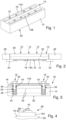
- Fig. 1 shows an aerated concrete support 10 according to the invention in accordance with a first embodiment of the invention.
- the aerated concrete support 10 consists of cuboid-shaped aerated concrete 12. Reinforcements can be provided within the cuboid-shaped aerated concrete 12, which Fig. 1 but are not recognizable, cf. but Fig. 3 .
- the aerated concrete beam 10 is provided with a reinforcement, the reinforcement comprising two elongated support rails 14A, 14B which extend substantially over the entire length of the aerated concrete beam and which are arranged parallel to each other and at a distance from each other.
- the distance between the two support rails 14A, 14B is approximately twice the distance of the side rail 14A to the Fig. 1 rear side edge or the distance of the support rail 14B to the Fig. 1 front side edge.
- the support rails 14A, 14B are each provided with four through holes, which Fig. 1 are concealed, and through each of which an aerated concrete screw 16 is inserted.
- the aerated concrete screws 16 are screwed in an invisible manner into drill holes in the aerated concrete 12 of the aerated concrete support 10.
- the aerated concrete screws 16 rest with the underside of their respective heads on the top of the respective support rail 14A, 14B and clamp the support rail 14A, 14B against a first outer side 18 of the aerated concrete support 10.
- a flowable adhesive is filled into the drill holes.
- the flowable adhesive is low viscosity and has about the same viscosity as warm honey.
- the flowable adhesive is pressed into areas of the aerated concrete 12 that border on the respective drill hole wall.
- the diameter of the drill holes is slightly smaller than or equal to the core diameter of the shaft of the aerated concrete screws 16.
- the thread of the aerated concrete screws thus engages in areas of the aerated concrete 12 that have been saturated with the flowable adhesive.
- the adhesive has hardened, the load-bearing capacity of the aerated concrete is significantly increased by the hardened adhesive. This also significantly increases the holding power of the aerated concrete screws compared to aerated concrete screws that are screwed into drill holes without flowable adhesive.
- the reinforcement is arranged such that the first outer side 18 is opposite a second outer side 20, onto which the main load is applied to the aerated concrete support 10.
- the second outer side 20 When using the aerated concrete beam 10 as a roof element, the second outer side 20 would consequently be at the top and the first outer side 18 at the bottom.
- Fig. 2 shows the aerated concrete beam 10 of the Fig. 1 when installed as a roof element.
- the aerated concrete beam 10 rests on a first support 22.
- the aerated concrete beam 10 rests on a second support 24.
- the two supports 22, 24 form, for example, parts of a roof construction.
- further aerated concrete beams 26, 28 are indicated in sections, which also form part of the roof surface.
- a solar system or a roof garden, or perhaps just a green roof is to be installed on an existing roof structure, for example the roof structure of an industrial hall
- the additional load from the solar systems and/or the green roof usually exceeds the permissible load-bearing capacity of the aerated concrete beams 10, 26, 28.
- the aerated concrete beam 10 and of course also the other aerated concrete beams 26, 28 can be reinforced so that they have an increased load-bearing capacity. This makes it possible to reinforce roofs or facades made of aerated concrete beams in such a way that solar systems can be installed on the roofs and facades and, for example, a green roof can also be installed on a roof.
- a reinforcement with the support rails 14A, 14B and aerated concrete screws 16 is arranged on the first outer side 18 of the aerated concrete support 10, wherein the first outer side 18 in Fig. 2 forms the underside of the aerated concrete beam 10.
- a roof load consequently acts on the opposite second outer side 20 of the aerated concrete beam 10. The roof load is symbolized by several arrows F.
- Fig. 2 an imaginary dashed line 30 is drawn in, which is arranged exactly halfway along the thickness of the aerated concrete support 10.
- Below the dashed line 30 is the so-called tension zone when the aerated concrete support 10 is loaded, in which the aerated concrete 12 of the aerated concrete support 10 is slightly stretched.
- Above the dashed line 30 is the so-called compression zone of the aerated concrete support 10, in which the aerated concrete 12 is slightly compressed when loaded.
- the support rails 14A, 14B reduce deflection of the aerated concrete beam 10 under load F and can thereby increase the load-bearing capacity of the aerated concrete beam 10.
- the aerated concrete beam 10 of the Fig. 2 was retrofitted with the reinforcement, i.e. the support rails 14A, 14B and the aerated concrete screws 16. If an aerated concrete beam is to be reinforced before it is installed in a structure, the support rails 14A, 14B can also extend over the entire length of the aerated concrete beam. The support rails would then also rest on the supports 22, 24.
- the aerated concrete screws 16 are dimensioned such that the thread of the aerated concrete screws 16 is arranged exclusively or at least for the most part in the pressure zone above the dashed line 30, see also Fig. 3 .
- a thread-free area of the shaft of the aerated concrete screws 16 is arranged in the tension zone below the dashed line 30.
- Fig. 3 shows a schematic sectional view of an inventive aerated concrete support 40 according to a further embodiment of the invention.
- each of the aerated concrete screws 16 has a head 42 with a drive formation and a cylindrical shaft 44.
- the drive formation on the head 42 is designed as an external hexagon, can be However, according to the invention, it can also be designed in any way, for example as a hexagon socket or the like.
- the shaft 44 Starting from the underside of the head 42, the shaft 44 initially has a smooth, thread-free section 46 and then, at the thread-free section 46, a thread 48 that extends to the end of the shaft 44.
- the underside of the head 42 rests on the top of the support rail 14A.
- the aerated concrete screws 16 prestress the support rail 14A against the first outer side 18 of the aerated concrete support 40, at least the support rail 14A is held in contact with the first outer side 18.
- the second outer side 20 is arranged opposite the first outer side 18.
- Two reinforcements 50 can be seen in the volume of the aerated concrete support 40.
- the reinforcements 50 can be designed as ring reinforcements, for example.
- the aerated concrete screws 16 are arranged in the aerated concrete support 40 in such a way that they do not touch the reinforcements 50.
- the aerated concrete screws 16 are each screwed into drill holes 52 in the aerated concrete support 40.
- the drill holes 52 are designed as blind holes and a depth of the drill holes is greater than half the thickness of the aerated concrete support 40, but smaller than the thickness of the aerated concrete support 40. With an aerated concrete support of approximately 20 to 30 cm thick, the drill holes extend to approximately 5 cm in front of the second outer side 20 of the aerated concrete support 40.
- the drill holes 52 have a diameter that corresponds to the core diameter of the aerated concrete screws 16. The core diameter is measured between two threads of the thread 48.
- the drill hole diameter can also be slightly smaller than the core diameter and, for example, be between 90% and 100% of the core diameter of the shaft 44 of the aerated concrete screws 16. This ensures that the thread flanks of the thread 48 engage in the aerated concrete 12 of the aerated concrete support 40.
- a flowable adhesive is introduced into the drill holes.
- This flowable adhesive is low-viscosity in the uncured state and has approximately the viscosity of warm honey. The viscosity of the flowable adhesive is such that it can be pressed into the pores of the aerated concrete 12 and then harden there.
- the flowable adhesive When screwing in the aerated concrete screws 16, the flowable adhesive is displaced from the drill hole by the shaft 44 of the aerated concrete screw 16, so that the flowable adhesive is pressed into an area 54 of the aerated concrete 12 which surrounds the drill hole and which is in Fig. 3 is indicated schematically.
- the thread flanks of the thread 48 of the aerated concrete screw 16 also engage in this area 54.
- the thread flanks of the thread 48 thus engage in the area 54, which is significantly strengthened by the hardened adhesive compared to the rest of the aerated concrete 12 of the aerated concrete support 40.
- the holding force of the aerated concrete screws 16 can thus be significantly increased compared to the aerated concrete 12 without adhesive.
- part of the flowable adhesive also emerges from the top of the drill holes and fills a gap between the shaft 44 and the inner wall of the through opening in the support rail 14A. A lateral movement of the support rail 14A relative to the shaft 44 of the screw is thereby prevented, so that the support rail 14A has a tension band effect.
- Fig. 4 shows a sectional view of another aerated concrete support 50 according to the invention, which has been provided with a reinforcement 62, also only shown in sections, with a support rail 14A and an aerated concrete screw 16.
- a large washer 64 which, like the support rail 14A, is made of aluminum, is arranged between the top of the support rail 14A and the bottom of the head of the aerated concrete screw 16.
- a small washer 66 is arranged between the top of the large washer 64 and the bottom of the head of the aerated concrete screw 16.
- the thickness of the large washer 64 is significantly greater than the thickness of the small washer 66 and, for example, three to four times as large.
- the diameter of the large washer 64 is approximately twice as large as the diameter of the small washer 66.
- the small washer 66 can, for example, be made of steel or can also be formed in one piece on the bottom of the head of the aerated concrete screw 16.
- the two washers 64, 66 serve to evenly distribute a prestressing force, which is applied from the underside of the head of the aerated concrete screw 16, to the support rail 14A.
- the support rail 14A rests with its underside on a first outer side 18 of the aerated concrete support 60.
- aerated concrete beams as roof elements, as facade elements or as door lintel elements or window lintel elements can be reinforced in such a way that they have an increased load-bearing capacity and that, for example, solar systems or green roofs can be arranged on or on these structures. If structures are manufactured If aerated concrete beams according to the invention are used, the roof loads of such structures can be significantly increased and the load-bearing capacity of facades made of the aerated concrete beams according to the invention can also be significantly increased compared to the use of conventional aerated concrete beams.
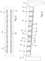
- Fig. 5 shows a bottom view of an aerated concrete support 10 according to the invention according to a fifth embodiment of the invention.
- the aerated concrete support 10 differs from the aerated concrete support 10 of Fig. 1 only in the design of the support rails 14A, 14B and the aerated concrete screws 16. As a result, only the differences of the aerated concrete beam 10 of the Fig. 5 to the aerated concrete beam 10 of the Fig. 1 explained.
- the support rails 14A, 14B are each made of fiber-reinforced plastic, for example glass fiber-reinforced epoxy resin.
- the support rails 14A, 14B each have 9 through holes, into each of which an aerated concrete screw 16 is inserted.
- the two support rails 14A, 14B are arranged parallel to each other and each end in front of the front side of the aerated concrete beam 10.
- the support rails 14A, 14B thus end in front of the area of the aerated concrete beam 10 in which it is placed on a support of a building, compare Fig. 6.
- Fig. 6 shows the aerated concrete beam 10 of the Fig. 5 in a sectional view and in the state laid on two supports 22, 24 of a structure not otherwise shown.
- the aerated concrete beam 10 can be used, for example, as a roof element and is therefore loaded with a surface load F from its second outer side 20.
- the several aerated concrete screws 16 have been screwed into pre-drilled holes in the aerated concrete support 10. How Fig. 6 As can be seen, the drill holes have been placed in such a way that they do not intersect with the reinforcements 50 of the aerated concrete support 10. If the drill holes or the aerated concrete screws touch the reinforcements 50 when screwed in, this is harmless. It is possible that a load from the aerated concrete screws 16 is even distributed more evenly over the volume of the aerated concrete support 10 when they touch the reinforcement. Within the scope of the invention, however, the aim is to place the drill holes and also the aerated concrete screws in such a way that they do not touch the reinforcements 50.
- the through holes in the support rail 14A are initially countersunk in the shape of a truncated cone and then have a short, circular cylindrical section.
- the aerated concrete screws 16 have countersunk heads.
- a truncated cone-shaped underside of the heads of the aerated concrete screws 16 lies flat in the truncated cone-shaped countersink of the through hole in the support rail 14A.
- the top of the heads of the aerated concrete screws 16 is arranged flush with a top of the support rail 14A, with the top in Fig. 6 the lower outside of the support rail 14A is meant.
- a flowable liquid adhesive is introduced into the drill holes, as shown in the Fig. 1 to 4 explained.
- This adhesive is displaced from the respective drill hole when the aerated concrete screws are screwed in and penetrates into an area 54 that surrounds the entire length of the drill hole.
- the flowable adhesive not only penetrates into the aerated concrete that surrounds the drill hole in the aerated concrete support 10, but is also pressed out of the drill hole into the circular cylindrical section of the through-opening in the support rail 14A. There, the flowable adhesive fills the space between the inner wall of the circular cylindrical section of the through-opening and the outer circumference of the shaft of the aerated concrete screw 16.
- the aerated concrete screws 16 are evenly distributed over the length of the aerated concrete beam 10. If, in a special case, the aerated concrete beam 10 is subjected to a higher load at a specific point, the reinforcement in this more highly loaded area can have several aerated concrete screws 16 at a closer distance than in less heavily loaded areas.
- Fig. 8 shows the aerated concrete beam 10 of the Fig. 5 and 6 next to two other aerated concrete beams 26, 28 in the cut state and in the installed state in a structure. Only the support 22 made of Fig. 6 is shown. It can be seen that the aerated concrete beams 10, 26, 28 are provided with a tongue and groove system with which they engage with each other at their longitudinal edges. The parallel arrangement of the support rails 14A, 14B can be clearly seen. It can also be seen that the aerated concrete screws 16 do not touch the reinforcements 50 in the aerated concrete beams.
- Fig. 7 shows a sectioned bottom view of the aerated concrete beams 10, 26, 28. At the Fig. 7 At the upper end there is a cutting plane, and also the Fig. 7 The lower end is cut off. The view goes into Fig. 7 on the first outer side of the aerated concrete beams 10, 26, 28, on each of which two support rails 14A, 14B arranged parallel to each other are arranged.
- the spacing of the support rails 14A, 14B on the aerated concrete beam 10 is greater than the spacing of the support rails 14A, 14B on the aerated concrete beams 26, 28.
- the spacing of the support rails 14A, 14B can be adjusted depending on the expected load on the aerated concrete beams 10, 26, 28.
Landscapes
- Engineering & Computer Science (AREA)
- Architecture (AREA)
- Mechanical Engineering (AREA)
- Civil Engineering (AREA)
- Structural Engineering (AREA)
- Chemical & Material Sciences (AREA)
- Chemical Kinetics & Catalysis (AREA)
- Electrochemistry (AREA)
- On-Site Construction Work That Accompanies The Preparation And Application Of Concrete (AREA)
Applications Claiming Priority (1)
| Application Number | Priority Date | Filing Date | Title |
|---|---|---|---|
| DE102023111184.1A DE102023111184A1 (de) | 2023-05-02 | 2023-05-02 | Verstärkung für einen Porenbetonträger, Porenbetonträger, Verwendung eines Porenbetonträgers, Verfahren zum Verstärken eines Porenbetonträgers und Verwendung einer Verstärkung |
Publications (1)
| Publication Number | Publication Date |
|---|---|
| EP4459073A1 true EP4459073A1 (fr) | 2024-11-06 |
Family
ID=90829191
Family Applications (1)
| Application Number | Title | Priority Date | Filing Date |
|---|---|---|---|
| EP24171997.0A Pending EP4459073A1 (fr) | 2023-05-02 | 2024-04-23 | Renforcement pour un support de béton poreux, support de béton poreux, utilisation d'un support de béton poreux, procédé de renforcement d'un support de béton poreux et utilisation d'un renforcement |
Country Status (2)
| Country | Link |
|---|---|
| EP (1) | EP4459073A1 (fr) |
| DE (1) | DE102023111184A1 (fr) |
Cited By (1)
| Publication number | Priority date | Publication date | Assignee | Title |
|---|---|---|---|---|
| WO2025125089A1 (fr) * | 2023-12-15 | 2025-06-19 | Fischerwerke Gmbh & Co. Kg | Système de renforcement d'élément de structure de support de bâtiment |
Citations (4)
| Publication number | Priority date | Publication date | Assignee | Title |
|---|---|---|---|---|
| JPH0438308A (ja) * | 1990-06-01 | 1992-02-07 | Ishikawajima Harima Heavy Ind Co Ltd | 床版補強方法 |
| DE19852339A1 (de) * | 1998-11-13 | 2000-05-18 | Toge Duebel A Gerhard Kg | Gasbeton-Schraube |
| EP2977528B1 (fr) * | 2014-07-24 | 2018-09-12 | CBP Guideway Systems GmbH | Système de renfort d'un ouvrage et procédé destiné à renforcer un ouvrage doté d'un tel système de renfort |
| EP3578832A1 (fr) * | 2018-06-07 | 2019-12-11 | Adolf Würth GmbH & Co. KG | Procédé d'agencement d'une vis de béton cellulaire dans le béton cellulaire, utilisation et agencement |
Family Cites Families (3)
| Publication number | Priority date | Publication date | Assignee | Title |
|---|---|---|---|---|
| US6976345B2 (en) * | 1999-04-05 | 2005-12-20 | Firouzeh Keshmiri | Cementitious based structural lumber product and externally reinforced lightweight retaining wall system |
| DE19944602A1 (de) * | 1999-05-26 | 2000-11-30 | Toge Duebel A Gerhard Kg | Verfahren zum Eindrehen einer gewindeschneidenden Schraube in ein Bohrloch und gewindeschneidende Schraube zur Durchführung des Verfahrens |
| DE102020115907A1 (de) * | 2019-08-14 | 2021-02-18 | Fischerwerke Gmbh & Co. Kg | Verfahren zu einer Befestigung eines zugfesten Verstärkungselements an einer Oberfläche eines Bauwerks |
-
2023
- 2023-05-02 DE DE102023111184.1A patent/DE102023111184A1/de active Pending
-
2024
- 2024-04-23 EP EP24171997.0A patent/EP4459073A1/fr active Pending
Patent Citations (4)
| Publication number | Priority date | Publication date | Assignee | Title |
|---|---|---|---|---|
| JPH0438308A (ja) * | 1990-06-01 | 1992-02-07 | Ishikawajima Harima Heavy Ind Co Ltd | 床版補強方法 |
| DE19852339A1 (de) * | 1998-11-13 | 2000-05-18 | Toge Duebel A Gerhard Kg | Gasbeton-Schraube |
| EP2977528B1 (fr) * | 2014-07-24 | 2018-09-12 | CBP Guideway Systems GmbH | Système de renfort d'un ouvrage et procédé destiné à renforcer un ouvrage doté d'un tel système de renfort |
| EP3578832A1 (fr) * | 2018-06-07 | 2019-12-11 | Adolf Würth GmbH & Co. KG | Procédé d'agencement d'une vis de béton cellulaire dans le béton cellulaire, utilisation et agencement |
Cited By (1)
| Publication number | Priority date | Publication date | Assignee | Title |
|---|---|---|---|---|
| WO2025125089A1 (fr) * | 2023-12-15 | 2025-06-19 | Fischerwerke Gmbh & Co. Kg | Système de renforcement d'élément de structure de support de bâtiment |
Also Published As
| Publication number | Publication date |
|---|---|
| DE102023111184A1 (de) | 2024-11-07 |
Similar Documents
| Publication | Publication Date | Title |
|---|---|---|
| EP3559484B1 (fr) | Système d'assemblage ou de blindage de composants | |
| EP1015774B1 (fr) | Fixation des lattes de bois sur le platelage d'un toit ou la fondation d'un mur composé entre autres de bois | |
| DE10341401B4 (de) | Verbundeinrichtung für eine Holz-Beton-Verbindung | |
| EP2397705B1 (fr) | Système d'ancrage pour le montage sans tension distant d'un élément de montage sur un support d'ancrage | |
| DE19938363A1 (de) | Schraubanker | |
| DE102011102825B4 (de) | Verbindungsanordnung und Verfahren zur Herstellung einer Durchstanzsicherung | |
| EP4459073A1 (fr) | Renforcement pour un support de béton poreux, support de béton poreux, utilisation d'un support de béton poreux, procédé de renforcement d'un support de béton poreux et utilisation d'un renforcement | |
| EP1582684B1 (fr) | Vis pour la fixation de profilés creux en matière plastique renforcés par des profilés métalliques sur une structure de support | |
| DE29805784U1 (de) | Schraube zur Befestigung von Latten aus Holz auf einem Dach- oder Wandunterbau | |
| EP1500768A2 (fr) | Dispositif de support et de fixation d'encadrements pour portes ou fenêtres à la périphérie d'une ouverture de paroi | |
| EP1699986B1 (fr) | Construction de parois en bois, du type a madriers en blocs | |
| AT511443B1 (de) | Einrichtung zur befestigung einer last | |
| DE102010020278B4 (de) | Vorrichtung zur Bereitstellung eines Befestigungspunktes an einem Profilelement | |
| WO2023062135A1 (fr) | Vis de cadre | |
| EP0697530B1 (fr) | Boulon d'ancrage pour béton ou similaire | |
| DE29811036U1 (de) | Schraube zur Abstandsbefestigung von Abdeckplatten oder Schienen an einem Unterbau | |
| DE3218457C2 (de) | Dübelbefestigung für Treppenstufen | |
| DE202020000211U1 (de) | Distanzstück und System zum dauerhaften Befestigen eines Bauteils an wenigstens einem Befestigungspunkt | |
| EP1039152B1 (fr) | Vis d'assemblage pour des profilés en bois avec des joints droits ou en onglet | |
| EP1457619A1 (fr) | Elément d'armature pour constructions en béton | |
| EP1319765A2 (fr) | Connections de poutres et poteaux formés de madriers ou de lattes en bois pour l'assemblage d'éléments de murs | |
| WO2010049355A1 (fr) | Vis et assemblage réalisé avec celle-ci | |
| EP3327216A1 (fr) | Fixation d'éléments de façade sur un mur de bâtiment | |
| WO2025149627A1 (fr) | Dispositif d'accouplement pour façades ou vitres de bâtiment | |
| DE29905532U1 (de) | Eck- oder Kämpferverbindung für zumindest teilweise aus Holzprofilen gebildete Fenster oder Türen, Fenster- oder Türrahmen o.dgl. |
Legal Events
| Date | Code | Title | Description |
|---|---|---|---|
| PUAI | Public reference made under article 153(3) epc to a published international application that has entered the european phase |
Free format text: ORIGINAL CODE: 0009012 |
|
| STAA | Information on the status of an ep patent application or granted ep patent |
Free format text: STATUS: THE APPLICATION HAS BEEN PUBLISHED |
|
| AK | Designated contracting states |
Kind code of ref document: A1 Designated state(s): AL AT BE BG CH CY CZ DE DK EE ES FI FR GB GR HR HU IE IS IT LI LT LU LV MC ME MK MT NL NO PL PT RO RS SE SI SK SM TR |
|
| STAA | Information on the status of an ep patent application or granted ep patent |
Free format text: STATUS: REQUEST FOR EXAMINATION WAS MADE |
|
| 17P | Request for examination filed |
Effective date: 20250428 |