EP4467809A1 - Druckverzögertes osmosesystem - Google Patents
Druckverzögertes osmosesystem Download PDFInfo
- Publication number
- EP4467809A1 EP4467809A1 EP23174499.6A EP23174499A EP4467809A1 EP 4467809 A1 EP4467809 A1 EP 4467809A1 EP 23174499 A EP23174499 A EP 23174499A EP 4467809 A1 EP4467809 A1 EP 4467809A1
- Authority
- EP
- European Patent Office
- Prior art keywords
- pressure
- stage
- membrane unit
- exchanger
- osmosis system
- Prior art date
- Legal status (The legal status is an assumption and is not a legal conclusion. Google has not performed a legal analysis and makes no representation as to the accuracy of the status listed.)
- Pending
Links
Images

Classifications
-
- F—MECHANICAL ENGINEERING; LIGHTING; HEATING; WEAPONS; BLASTING
- F03—MACHINES OR ENGINES FOR LIQUIDS; WIND, SPRING, OR WEIGHT MOTORS; PRODUCING MECHANICAL POWER OR A REACTIVE PROPULSIVE THRUST, NOT OTHERWISE PROVIDED FOR
- F03G—SPRING, WEIGHT, INERTIA OR LIKE MOTORS; MECHANICAL-POWER PRODUCING DEVICES OR MECHANISMS, NOT OTHERWISE PROVIDED FOR OR USING ENERGY SOURCES NOT OTHERWISE PROVIDED FOR
- F03G7/00—Mechanical-power-producing mechanisms, not otherwise provided for or using energy sources not otherwise provided for
- F03G7/008—Mechanical-power-producing mechanisms, not otherwise provided for or using energy sources not otherwise provided for characterised by the actuating element
- F03G7/015—Actuators using the difference in osmotic pressure between fluids
-
- B—PERFORMING OPERATIONS; TRANSPORTING
- B01—PHYSICAL OR CHEMICAL PROCESSES OR APPARATUS IN GENERAL
- B01D—SEPARATION
- B01D61/00—Processes of separation using semi-permeable membranes, e.g. dialysis, osmosis or ultrafiltration; Apparatus, accessories or auxiliary operations specially adapted therefor
- B01D61/02—Reverse osmosis; Hyperfiltration ; Nanofiltration
- B01D61/06—Energy recovery
-
- B—PERFORMING OPERATIONS; TRANSPORTING
- B01—PHYSICAL OR CHEMICAL PROCESSES OR APPARATUS IN GENERAL
- B01D—SEPARATION
- B01D61/00—Processes of separation using semi-permeable membranes, e.g. dialysis, osmosis or ultrafiltration; Apparatus, accessories or auxiliary operations specially adapted therefor
- B01D61/02—Reverse osmosis; Hyperfiltration ; Nanofiltration
- B01D61/025—Reverse osmosis; Hyperfiltration
-
- B—PERFORMING OPERATIONS; TRANSPORTING
- B01—PHYSICAL OR CHEMICAL PROCESSES OR APPARATUS IN GENERAL
- B01D—SEPARATION
- B01D61/00—Processes of separation using semi-permeable membranes, e.g. dialysis, osmosis or ultrafiltration; Apparatus, accessories or auxiliary operations specially adapted therefor
- B01D61/02—Reverse osmosis; Hyperfiltration ; Nanofiltration
- B01D61/08—Apparatus therefor
-
- B—PERFORMING OPERATIONS; TRANSPORTING
- B01—PHYSICAL OR CHEMICAL PROCESSES OR APPARATUS IN GENERAL
- B01D—SEPARATION
- B01D63/00—Apparatus in general for separation processes using semi-permeable membranes
-
- F—MECHANICAL ENGINEERING; LIGHTING; HEATING; WEAPONS; BLASTING
- F03—MACHINES OR ENGINES FOR LIQUIDS; WIND, SPRING, OR WEIGHT MOTORS; PRODUCING MECHANICAL POWER OR A REACTIVE PROPULSIVE THRUST, NOT OTHERWISE PROVIDED FOR
- F03G—SPRING, WEIGHT, INERTIA OR LIKE MOTORS; MECHANICAL-POWER PRODUCING DEVICES OR MECHANISMS, NOT OTHERWISE PROVIDED FOR OR USING ENERGY SOURCES NOT OTHERWISE PROVIDED FOR
- F03G7/00—Mechanical-power-producing mechanisms, not otherwise provided for or using energy sources not otherwise provided for
- F03G7/025—Mechanical-power-producing mechanisms, not otherwise provided for or using energy sources not otherwise provided for characterised by its use
- F03G7/0252—Motors; Energy harvesting or waste energy recovery
-
- B—PERFORMING OPERATIONS; TRANSPORTING
- B01—PHYSICAL OR CHEMICAL PROCESSES OR APPARATUS IN GENERAL
- B01D—SEPARATION
- B01D2313/00—Details relating to membrane modules or apparatus
- B01D2313/24—Specific pressurizing or depressurizing means
- B01D2313/243—Pumps
-
- B—PERFORMING OPERATIONS; TRANSPORTING
- B01—PHYSICAL OR CHEMICAL PROCESSES OR APPARATUS IN GENERAL
- B01D—SEPARATION
- B01D2313/00—Details relating to membrane modules or apparatus
- B01D2313/24—Specific pressurizing or depressurizing means
- B01D2313/246—Energy recovery means
Definitions
- the present invention relates to a pressure retarded osmosis system
- a membrane unit having a high-pressure inlet connection and a high-pressure outlet connection on one side of a membrane arrangement and a low-pressure inlet connection and a low-pressure outlet connection on the other side of the membrane arrangement, wherein the high-pressure inlet connection is connected to a pressure exchanger, and the high-pressure outlet connection is connected to a motor and to a high-pressure inlet port of the pressure exchanger.
- Such a pressure retarded osmosis system is known, for example, from EP 2 153 881 A1 .
- a difference between the salt concentrations of two liquids is used to gain energy.
- the high-pressure side of the membrane unit i.e. the area between the high-pressure inlet connection and the high-pressure outlet connection is provided with a flow of a liquid having a high salt concentration and a high-pressure
- the low-pressure side of the membrane unit i.e. the area between the low-pressure inlet connection and the low-pressure outlet connection of the membrane unit is provided with a flow of a liquid having a much lower salt concentration and a much lower pressure.
- the membrane which is a semi permeable membrane, allows the liquid having the lower concentration of salt to migrate to the other side.
- the flow at the high-pressure outlet connection can be divided into one part which is supplied to the motor to generate mechanical power and in one part which is guided back to the pressure exchanger.
- the term "motor” is used for a device which produces mechanical energy when driven by a flow of hydraulic fluid.
- the motor could also be called a turbine that generates mechanical power which is converted into electrical power.
- the pressure exchanger transfers the high-pressure of the fluid at the high-pressure outlet connection of the membrane unit to the fluid supplied to the high-pressure inlet connection of the membrane unit.
- the pressure of the liquid at the high-pressure side of the membrane arrangement should be higher than 120 bar or more.
- the object underlying the invention is to operate a pressure retarded osmosis system at a pressure higher than 60 to 80 bar, in particular higher than 100 bar and preferably higher than 120 bar.
- the pressure exchanger comprises at least a first stage and a second stage, the first stage being arranged nearest to the high-pressure inlet connection of the membrane unit, wherein the high-pressure inlet port of the first stage is connected to the high-pressure outlet connection of the membrane unit and a high-pressure inlet port of the second stage is provided with fluid having a lower pressure and a high-pressure outlet port of the second stage is connected to a low-pressure inlet port of the first stage.
- the two stages of the pressure exchanger are connected in series at least for the flow into the membrane unit.
- the two stages of the pressure exchanger can also be in form of two separate pressure exchanger units.
- each stage has to increase the pressure of the incoming liquid with a smaller pressure difference.
- the first stage can increase the pressure from 70 bar to 200 bar, wherein the second stage increases the pressure from a supply pressure of approximately 2 to 10 bar to the 70 bar required at the inlet port of the first stage. Since the two stages need not to handle such a large pressure difference operation of these pressure exchanger stages is less complicated.
- the pressure at the high-pressure outlet connection of the membrane unit can be transferred to the fluid entering the high-pressure inlet connection of the membrane unit, so that the energy stored in the high-pressure liquid is not wasted.
- the mechanical energy produced by the motor or turbine can be used to drive another device, for example an electric machine operating as generator or the motor can be used directly to drive elements of the pressure exchanger.
- the membrane unit is a first membrane unit and the motor is a first motor, and a high-pressure inlet connection of a second membrane unit is connected to an outlet of the first motor and a second motor is connected to the high-pressure outlet of the second membrane unit.
- the liquid leaving the first membrane unit still has a rather high salt concentration, although it is diluted by liquid which has been fed to the low-pressure inlet connection of the first membrane unit.
- the pressure reduction across the first motor is tuned so that there is still enough pressure available for performing a second step of generation of mechanical energy. This second step can be performed by means of the second membrane unit. In the second membrane unit there is the same pressure retarded osmosis, however, on a lower level, i.e. having a lower salt concentration and a lower pressure.
- the low-pressure outlet port of the first stage of the pressure exchanger is connected to the high-pressure inlet connection of the second membrane unit.
- the first stage of the pressure exchanger bridges the first motor.
- the pressure at the low-pressure outlet port of the first stage is still high enough to be used in the pressure retarded osmosis in the second membrane unit.
- the high-pressure outlet connection of the second membrane unit is connected to the high-pressure inlet port of the second stage of the pressure exchanger.
- a pressure at the high-pressure outlet connection of the second membrane unit corresponds basically to the pressure at the high-pressure inlet connection of the second membrane unit, so that this pressure can simply be used as inlet pressure to the second stage of the pressure exchanger.
- the operating conditions for the two stages of the pressure exchanger have not been changed.
- a first pressure difference over the first stage of the pressure exchanger corresponds to a second pressure difference over the first motor.
- the low-pressure connection of the first membrane unit is connected to a first supply pump and the low-pressure connection of the second membrane unit is connected to a second supply pump.
- the two supply pumps are only necessary to produce a flow of liquid through the low pressure side of the membrane units. Thus, high-pressure pumps are not required here.
- the second supply pump produces a larger volume flow than the first supply pump.
- the flow of liquid entering the high-pressure inlet connection of the second membrane unit is larger than the flow of liquid entering the high-pressure inlet connection of the first membrane unit.
- In the first membrane unit at least part of the liquid supplied to the low-pressure inlet connection of the first membrane unit is added to the flow supplied to the high-pressure inlet connection.
- a feed pump is arranged upstream of at least one of the high-pressure inlet ports.
- a feed pump is used in order to produce a flow of fluid through the respective high-pressure loop. It is sufficient that the feed pump raises the pressure only by a small amount, for example by 1 bar.
- the feed pump is a positive displacement pump.
- the positive displacement pump is used as flow meter.
- this pump provides an information how much fluid is being running through the pump and this again means that it is possible from this information to control the behaviour of the pressure exchanger, for example the rotational speed.
- At least one of the stages of the pressure exchanger comprises more than one pressure exchange unit. It is thus possible to separate the stage and to use two or more pressure exchange units. Each of these pressure exchange units can be dimensioned with a smaller size.
- the second stage of the pressure exchanger comprises more pressure exchange units than the first stage.
- the pressure exchange unit of the same stage have the same capacity.
- these pressure exchange units are interchangeable. This reduces costs for maintenance.
- At least two pressure exchange units of the same stage are driven by a common drive. They can, for example, be arranged on the same double axle electric motor making the system more cost effective.
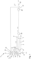
- a pressure retarded osmosis system 1 comprises a membrane unit 2.
- the membrane unit 2 comprises a high-pressure inlet connection 3 and a high-pressure outlet connection 4 on one side of a membrane arrangement 5 and a low-pressure inlet connection 6 and a low-pressure outlet connection 7 on the other side of the membrane arrangement 5.
- the membrane arrangement 5 is simply illustrated as a line. However, since a rather high area of the membrane is required, the membrane arrangement 5 can have one or more semipermeable membranes having a more sophisticated form.
- the low-pressure inlet connection 6 is connected to a supply pump 8.
- the supply pump 8 supplies a liquid with low salt concentration, for example fresh water, to the low-pressure inlet connection 6 of the membrane unit 2.
- the high-pressure inlet connection 3 is connected to a pressure exchanger 9.
- the pressure exchanger 9 comprises a first stage 10 and a second stage 11.
- the first stage 10 is the stage nearest to the high-pressure inlet connection 3 of the membrane unit 2.
- the sequence of the stages 10, 11 is seen in a direction from the membrane unit 2.
- the first stage 10 comprises a high-pressure inlet port 12, a high-pressure outlet port 13, a low-pressure inlet port 14 and a low-pressure outlet port 15.
- the second stage 11 comprises a high-pressure inlet port 16, a high-pressure outlet port 17, low-pressure inlet port 18 and a low-pressure outlet port 19.
- the high-pressure outlet connection 4 of the membrane unit 2 is connected to a motor arrangement 20, 20'. Furthermore, the high-pressure outlet connection 4 of the membrane unit 2 is connected to the high-pressure inlet port 12 of the first stage 10 of the pressure exchanger 9. The high-pressure outlet port 13 of the first stage 10 of the pressure exchanger 9 is connected to the high-pressure inlet connection 3 of the membrane unit 2. The low-pressure outlet port 15 of the first stage 10 of the pressure exchanger 9 is connected to the high-pressure inlet port 16 of the second stage 11 of the pressure exchanger 9. The high-pressure outlet port 17 of the second stage is connected to the low-pressure inlet port 14 of the first stage. The low-pressure inlet port 18 is connected to a further supply pump (not shown).
- the low-pressure outlet port 19 of the second stage 11 is connected to an outlet side 21 of the motor arrangement 20, 20'.
- the outlet side 21 of the last motor (in flow direction) is connected to an outlet 22 of the pressure retarded osmosis system.
- the motor arrangement 20, 20' is driven by the fluid coming from the high-pressure outlet connection 4 of the membrane unit 2, i.e. it uses the high-pressure of this liquid.
- the motor arrangement 20, 20' can have different forms. It is possible to use a single motor 20, two motors 20, 20' as shown, or more than two motors.
- the motor or motors 20, 20' can convert this "potential energy" of the liquid in another form of energy, for example electric energy. In this case the motors 20, 20'drive an electric generator. The electric energy of this generator can then be used to drive the supply pump 8 and/or the stages 10, 11 of the pressure exchanger 9. However, in some cases it is not necessary to produce electrical energy as an intermediate energy. It is also possible to use the mechanical energy directly to drive another pump or elements of the pressure exchanger 9. When more than one motor is used, the pressure difference over each motor can be kept smaller than the pressure difference between the
- a feed pump (not shown in Fig. 1 ) may be arranged in the high-pressure loop, i.e. in the connection between the high-pressure outlet connection 4 of the membrane unit 2 and the high-pressure inlet port 12 of the pressure exchanger 9. This feed pump helps to let the liquid in the high-pressure connection flow.
- the feed pump raises the pressure only by a small amount, for example by 1 bar. The pressure increase is chosen just to have the liquid "running".
- the feed pump can be in form of a positive displacement pump. In this case, it can be detected how much liquid is being running through the feed pump and this again means that it is possible to regulate based on this information the behaviour of the pressure-exchanger 9, for example controlling the RPM of the pressure exchanger 9.
- the second stage 11 of the pressure exchanger 9 comprises more pressure exchange units than the first stage 10. It is, for example, possible to have several small pressure exchange units increasing the pressure from 1 to 70 bar in the second stage 11 and one big pressure exchange unit increasing the pressure from 70 to 200 bar in the first stage 10. This should increase the efficiency because the internal leakage is not increasing proportional with volume flow.
- the numbers are used only as example.
- the second stage 11 of the pressure exchanger 9 comprises two or more pressure exchangers
- these pressure exchange units have the same capacity. In this way they could be arranged on the same axle of an electric motor that in this way reduce Capex, footprint and increases a bit efficiency. In other words, at least two pressure exchange units of the same stage 11 are driven by a common drive.
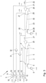
- Fig. 2 shows a second embodiment of a retarded osmosis system 1 in which some elements have been doubled, so that the membrane unit 2 is now termed “first membrane unit” and one of the motors, namely the motor 20, is now termed “first motor”.
- This single first motor 20 can also be replaced by a two or more motors.
- the retarded osmosis system 1 comprises also a second motor 24 which can also be replaced by two or more motors.
- the supply pump 8 is termed first supply pump and the second membrane unit 23 is connected to a second supply pump 25.
- the second membrane unit 23 comprises a high-pressure inlet connection 26, a high-pressure outlet connection 27, a low-pressure inlet connection 28 connected to the second supply pump 25, a low-pressure outlet connection 29 and a second membrane arrangement 30.
- the high-pressure outlet connection 27 is connected to the second motor 24.
- the high-pressure inlet connection 26 is connected to the first motor 20.
- the connection of the pressure exchanger 9 to the first membrane unit 2 is the same as in the embodiment shown in Fig. 1 with the following exception:
- the low-pressure outlet port 15 of the first stage 10 of the pressure exchanger 9 is connected to the high-pressure inlet connection 26 of the second membrane unit 23, whereas the high-pressure outlet connection 27 of the second membrane unit is connected to the high-pressure inlet connection 16 of the second stage 11 of the pressure exchanger 9.
- a volume flow supplied to the first stage 10 of the pressure exchanger 9 is taken from the low-pressure outlet port 15 and supplied to the high-pressure inlet connection 26 of the second membrane unit 23.
- the second supply pump 25 supplies a larger volume flow of liquid fed to the second membrane unit 23.
- a first pressure difference over the first stage 10 of the pressure exchanger 9, i.e. a pressure difference between the high-pressure inlet port 12 and the low-pressure outlet port 15, corresponds to a second pressure difference over the first motor 20.
- Fig. 3 shows a third embodiment of a retarded osmosis system 1 which basically corresponds to the second embodiment shown in Fig. 2 . Same elements are denoted with the same reference numerals.
- a first feed pump 31 is arranged in the high-pressure loop of the of the first stage 10 of the pressure exchanger 9.
- a second feed pump 32 is arranged in the high-pressure loop of the second stage 11 of the pressure exchanger 9, i.e. in a line connecting the high-pressure outlet connection 27 of the second membrane unit 23 to the high-pressure inlet connection 16 of the second stage 11 of the pressure exchanger 9.
- This feed pump 32 has the same effect as the feed pump 31 in the other high-pressure loop.
- the additional feed pumps 31, 32 can be arranged in the position shown. It is, however, also possible to arrange the first feed pump 31 directly at the high-pressure inlet connection 3 of the membrane unit 2 and/or to arrange the second feed pump 32 between the high-pressure outlet port 17 of the second stage 11 of the pressure exchanger 9 and the low-pressure inlet port 14 of the first stage 10 of the pressure exchanger 9.
- the feed pumps 31, 32 can be separate elements, but they can also be integrated in the pressure exchanger 9.
Landscapes
- Chemical & Material Sciences (AREA)
- Engineering & Computer Science (AREA)
- Water Supply & Treatment (AREA)
- Chemical Kinetics & Catalysis (AREA)
- Nanotechnology (AREA)
- Combustion & Propulsion (AREA)
- Mechanical Engineering (AREA)
- General Engineering & Computer Science (AREA)
- Analytical Chemistry (AREA)
- Separation Using Semi-Permeable Membranes (AREA)
Priority Applications (3)
| Application Number | Priority Date | Filing Date | Title |
|---|---|---|---|
| EP23174499.6A EP4467809A1 (de) | 2023-05-22 | 2023-05-22 | Druckverzögertes osmosesystem |
| US18/665,888 US20240390854A1 (en) | 2023-05-22 | 2024-05-16 | Pressure retarded osmosis system |
| CN202410639114.4A CN118987970A (zh) | 2023-05-22 | 2024-05-22 | 压力延迟渗透系统 |
Applications Claiming Priority (1)
| Application Number | Priority Date | Filing Date | Title |
|---|---|---|---|
| EP23174499.6A EP4467809A1 (de) | 2023-05-22 | 2023-05-22 | Druckverzögertes osmosesystem |
Publications (1)
| Publication Number | Publication Date |
|---|---|
| EP4467809A1 true EP4467809A1 (de) | 2024-11-27 |
Family
ID=86497878
Family Applications (1)
| Application Number | Title | Priority Date | Filing Date |
|---|---|---|---|
| EP23174499.6A Pending EP4467809A1 (de) | 2023-05-22 | 2023-05-22 | Druckverzögertes osmosesystem |
Country Status (3)
| Country | Link |
|---|---|
| US (1) | US20240390854A1 (de) |
| EP (1) | EP4467809A1 (de) |
| CN (1) | CN118987970A (de) |
Citations (3)
| Publication number | Priority date | Publication date | Assignee | Title |
|---|---|---|---|---|
| WO2019051588A1 (en) * | 2017-09-12 | 2019-03-21 | Pani Energy Inc. | ADAPTIVE MEMBRANE SYSTEMS |
| WO2021165337A1 (en) * | 2020-02-17 | 2021-08-26 | Saltpower Holding Aps | Osmotic solution mining |
| WO2023036943A1 (en) * | 2021-09-10 | 2023-03-16 | Saltpower Holding Aps | Anti-scalant process for an osmotic unit |
-
2023
- 2023-05-22 EP EP23174499.6A patent/EP4467809A1/de active Pending
-
2024
- 2024-05-16 US US18/665,888 patent/US20240390854A1/en active Pending
- 2024-05-22 CN CN202410639114.4A patent/CN118987970A/zh active Pending
Patent Citations (3)
| Publication number | Priority date | Publication date | Assignee | Title |
|---|---|---|---|---|
| WO2019051588A1 (en) * | 2017-09-12 | 2019-03-21 | Pani Energy Inc. | ADAPTIVE MEMBRANE SYSTEMS |
| WO2021165337A1 (en) * | 2020-02-17 | 2021-08-26 | Saltpower Holding Aps | Osmotic solution mining |
| WO2023036943A1 (en) * | 2021-09-10 | 2023-03-16 | Saltpower Holding Aps | Anti-scalant process for an osmotic unit |
Non-Patent Citations (1)
| Title |
|---|
| SOLTANI ROGHAYEH ET AL: "Modeling and simulation of the dual stage pressure retarded osmosis systems", DESALINATION, vol. 460, 19 March 2019 (2019-03-19), pages 28 - 40, XP085643847, ISSN: 0011-9164, DOI: 10.1016/J.DESAL.2019.02.010 * |
Also Published As
| Publication number | Publication date |
|---|---|
| CN118987970A (zh) | 2024-11-22 |
| US20240390854A1 (en) | 2024-11-28 |
Similar Documents
| Publication | Publication Date | Title |
|---|---|---|
| CN102138007B (zh) | 反渗透设备 | |
| US6468431B1 (en) | Method and apparatus for boosting interstage pressure in a reverse osmosis system | |
| DK2121169T3 (en) | Central pumping and energy recovery in a reverse osmosis system | |
| US7214315B2 (en) | Pressure exchange apparatus with integral pump | |
| US6797173B1 (en) | Method and apparatus for membrane recirculation and concentrate energy recovery in a reverse osmosis system | |
| US12268991B2 (en) | Reverse osmosis system | |
| CN102858436B (zh) | 反渗透系统 | |
| MacHarg | Retro-fitting existing SWRO systems with a new energy recovery device | |
| JP2004513774A (ja) | 水を脱塩させるための方法および装置 | |
| US20230398493A1 (en) | System for reverse osmosis and for pressure retarded osmosis | |
| EP4467809A1 (de) | Druckverzögertes osmosesystem | |
| US20240100481A1 (en) | System for reverse osmosis | |
| CN115475522B (zh) | 反渗透装置 | |
| US10906000B2 (en) | Method and system for performing reverse osmosis with brine recirculation and energy recovery | |
| JP7644948B2 (ja) | 被処理液の膜処理方法および装置 | |
| EP1315552B1 (de) | Verfahren und vorrichtung für ein effizienteres umkehrosmosesystem | |
| MacHarg et al. | How to design and operate SWRO systems built around a new pressure exchanger device | |
| EP1429074B1 (de) | Anordnung und Methode für die Wasserspeisung einer Dampfturbinenanlage | |
| CN119053555A (zh) | 混合能量回收系统 | |
| JPH11236901A (ja) | 油圧ブースタ装置 |
Legal Events
| Date | Code | Title | Description |
|---|---|---|---|
| PUAI | Public reference made under article 153(3) epc to a published international application that has entered the european phase |
Free format text: ORIGINAL CODE: 0009012 |
|
| STAA | Information on the status of an ep patent application or granted ep patent |
Free format text: STATUS: THE APPLICATION HAS BEEN PUBLISHED |
|
| AK | Designated contracting states |
Kind code of ref document: A1 Designated state(s): AL AT BE BG CH CY CZ DE DK EE ES FI FR GB GR HR HU IE IS IT LI LT LU LV MC ME MK MT NL NO PL PT RO RS SE SI SK SM TR |
|
| STAA | Information on the status of an ep patent application or granted ep patent |
Free format text: STATUS: REQUEST FOR EXAMINATION WAS MADE |
|
| 17P | Request for examination filed |
Effective date: 20250430 |