EP4470965A1 - Machine de remplissage rotative - Google Patents
Machine de remplissage rotative Download PDFInfo
- Publication number
- EP4470965A1 EP4470965A1 EP24179383.5A EP24179383A EP4470965A1 EP 4470965 A1 EP4470965 A1 EP 4470965A1 EP 24179383 A EP24179383 A EP 24179383A EP 4470965 A1 EP4470965 A1 EP 4470965A1
- Authority
- EP
- European Patent Office
- Prior art keywords
- shutter member
- product
- filling
- nozzle
- filling machine
- Prior art date
- Legal status (The legal status is an assumption and is not a legal conclusion. Google has not performed a legal analysis and makes no representation as to the accuracy of the status listed.)
- Pending
Links
Images


Classifications
-
- B—PERFORMING OPERATIONS; TRANSPORTING
- B67—OPENING, CLOSING OR CLEANING BOTTLES, JARS OR SIMILAR CONTAINERS; LIQUID HANDLING
- B67C—CLEANING, FILLING WITH LIQUIDS OR SEMILIQUIDS, OR EMPTYING, OF BOTTLES, JARS, CANS, CASKS, BARRELS, OR SIMILAR CONTAINERS, NOT OTHERWISE PROVIDED FOR; FUNNELS
- B67C3/00—Bottling liquids or semiliquids; Filling jars or cans with liquids or semiliquids using bottling or like apparatus; Filling casks or barrels with liquids or semiliquids
- B67C3/02—Bottling liquids or semiliquids; Filling jars or cans with liquids or semiliquids using bottling or like apparatus
- B67C3/20—Bottling liquids or semiliquids; Filling jars or cans with liquids or semiliquids using bottling or like apparatus with provision for metering the liquids to be introduced, e.g. when adding syrups
- B67C3/206—Bottling liquids or semiliquids; Filling jars or cans with liquids or semiliquids using bottling or like apparatus with provision for metering the liquids to be introduced, e.g. when adding syrups using arrangements of cylinders and pistons
Definitions
- the present invention falls within the field of devices to fill a container with a filling product in a filling plant.
- the filling device can be installed on a filling machine of the rotary type.
- filling devices in filling systems to introduce the respective filling product into containers to be filled.
- Said devices are suitable for processing different types of products, for example a liquid product, even carbonated or semi-liquid, such as a sauce, or a viscous product, such as an oil, or a fibrous product, such as a pulp or a juice, or a product with two phases i.e. liquid and solid, such as a minestrone or a soup, etc.
- the containers can, for example, be PET or glass containers, in particular bottles, cans, jars, etc.
- the containers may, for example, be PET or glass containers, in particular bottles, cans, jars, etc.
- the containers are arranged under the filling device, and in particular under a nozzle of said filling device.
- the filling device generally comprises, above said nozzle, a diverting valve and a dosing device.
- the nozzle comprises an exit mouth from which the product exits to enter the container to be filled.
- a corresponding amount of filling product is introduced into the dosing device, for example, by means of a suctioning system due to the movement of a piston inside a filling chamber of the dosing device.
- the diverting valve is generally of the rotary type, and comprises a body valve that is movable relative to a stationary seat of the diverting valve.
- the achievement of the two suctioning and filling positions of the diverting valve is generally carried out by means of a control lever, which is integral with the valve body which engages in a mechanical cam of the filling machine and puts said valve body in rotation inside the valve seat.
- valve body The rotation of the valve body between a suction position and a filling position allows performing the suctioning phase and the filling phase of the device, respectively.
- the body valve is positioned as to put in fluid comunication the filling chamber of the dosing device with the tanks containing the product; the plunger of the dosing device rises to create a suctioning effect that leads to the filling of the chamber with the product.
- the valve body does not allow the passage of product from the filling chamber of the doser, to the nozzle.
- valve body is positioned so as to put in fluid communication the filling chamber of the dosing device with the nozzle; the plunger of the dosing device lowers to make the product exit the filling chamber.
- the valve body closes the passage of the product between the filling chamber of the dosing device and the tanks containing the product.
- Solutions are known in the prior art, that provide, between the diverting valve and the nozzle, a discharge manifold on which a shutter member acts, which is movable between an open position in which it allows the passage of the product to the nozzle and a closed position, in which it prevents said passage.
- the shutter member operates synchronized with the diverting valve so that, when the diverting valve is in the suctioning phase, the shutter member is closed, i.e., it blocks the passage of the product from the discharge manifold to the nozzle.
- the shutter member when the diverting valve is in the filling phase, the shutter member is open, i.e., it allows for the passage of the product from the discharge manifold to the nozzle.
- the dosing valve, and the nozzle are in fluid comunication.
- rotary filling machines in which the dosing plunger reaches the two suctioning and filling positions via a driving member integral with the the plunger body that engages in a mechanic cam of the filling machine and puts in translation said plunger inside the filling chamber of the dosing device.
- the shutter member which according to the prior art is set in motion by mechanical means present on the rotary filler, i.e., it comprises an engagement member that cooperates with a mechanic cam of the filling machine.
- the dosing plunger, diverting valve, and shutter member are driven by the cams of the filling machine and in particular at each relative position between the cam and filling device a precise working phase corresponds.
- the dosing plunger, diverting valve, and shutter member are synchronized with each other.
- a disadvantage of this solution is due to the fact that when the rotary filler needs to be stopped instantaneously, for example due to an emergency stop, the filling devices that are in the position of filling continue to make the product exit, and in greater amount, when the system starts to show wear.
- the dosing plunger remains stationary, but, due to gravity, the product contained in the filling chamber keeps outflowing.
- Another disadvantage is due to the fact that the dosing plunger, the diverting valve and the shutter member constrain their working phase to each specific position of the filling device on the machine.
- the operation of the filling device is constrained to the rotation of the rotary machine.
- Dosing plunger, diverting valve and shutter member open and close always togheter according to the same times, positions, and law of motion, always being constrained to the position of the device during the rotation of the machine, not allowing to manage optimized openings/closures for different products.
- the known machines are not able to properly process products having too different densities, because the closure of the shutter member always occurs according to the same law of motion, being the shutter member driven by the mechanical cams of the filling machine in which, to each relative position between cam and filling device a precise working position corresponds.
- the shutter member always has to perform the closure cycle, while for some products such as, for example, mayionnaise, it would be more advantageous not to perform a closure of the shutter member.
- the technical problem underlying the present invention is to provide a device for filling containers that is structurally and functionally designed to overcome one or more of the limitations set out above with reference to the cited prior art.
- a main aim of the invention is to develop a rotary filling machine with a device for filling containers with a nozzle capable of operating in an unconstrained manner relative to the working position of the device on the rotary filling machine.
- the filling device is able to block the exit of the product also when the rotary filling machine is stopped.
- a rotary filling machine with a device for filling containers comprising a shutter member able to perform an adjustable and unconstrained closure/opening, independently of the working phase that is in progress in the filling machine, which makes the solution flexible to the different types of filling and to a plurality of more or less viscous products.
- said shutter member allows performing a precise and reliable closure, during the operational filling phases.
- Said shutter member allows a precise and instantaneous closure with elimination of the dripping and the dripping times.
- a rotary filling machine comprising a plurality of devices for filling containers with a filling product of any type, for example liquid, or a product with two phases, in which each container is arranged below the filling device.
- said device comprises, from top to bottom, a dosing device, a diverting valve and a nozzle located in the proximity of the container, wherein, through the diverting valve, a corresponding amount of filling product is introduced into the dosing device, and subsequently transferred to the nozzle, from which the product exits to be inserted into the container.
- a discharge manifold of the product isprovided between the diverting valve and the nozzle.
- a shutter member operates to allow/prevent the passage of the product to the nozzle 10.
- said device comprises handling means to activate/deactivate the shutter member, during the operational phases of the filling machine, independently of the working position of the filling device on the rotary filling machine.
- This also allows making a more flexible machine for use with different products, allowing to manage the shutter member with different times, positions and laws of motion.
- This also allows achieving a shutter member that is able to differentiate the working manner, for example, performing multiple closures, partial closures, or openings, or not performing the closure.
- the handling means are configured to translate according to a vertical direction said shutter member between at least one first position and a second position, and vice versa.
- a possible embodiment provides that said handling means are able to bring the shutter member to the second position, which matches with a closure position when the rotary filling machine moves from the operational phase to the stop phase independently of the working phase at which the machine has stopped.
- the handling means move the shutter member independently of the operational position of the dosing device and/or the diverting valve.
- the shutter member can open and close according to times, positions and laws of motion that are not constrained to those of the dosing plunger and/or the diverting valve.
- the shutter member when the diverting valve is in the filling phase, the shutter member is preferably at the first position, which allows the passage of the product from the discharge manifold to the nozzle, vice versa, when the diverting valve is in the suctioning phase, the shutter member is preferably at the second position, that blocks the passage of the product from the discharge manifold to the nozzle.
- the handling means comprise drive and management members that allow to vary the management of said handling means to adapt the operation of the shutter member to particular working and product conditions.
- the discharge manifold comprises an inlet channel and a output channel, which intercepts a discharge duct, located between the discharge manifold and the nozzle, and in which the shutter member operates to allow or prevent a fluid comunication.
- said discharge duct extends above the nozzle and preferably coaxial with a through hole of the nozzle.
- the shutter member comprises a plug, in a preferably cylindrical shape, which is adapted to slide at least inside the discharge duct.
- said handling means comprise a piston, preferably of the pneumatic type.
- the shutter device and the handling means are located side by side to the dosing device, preferably to the filling chamber.
- a device 1 for filling containers 1 with a given filling product is depicted.
- Said product preferably liquid
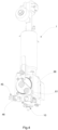
- Said device 1 is installable in a filling plant in particular in a rotary filling machine 200.
- a rotary filling machine 200 is depicted, onto which a plurality of devices 1 are installed.
- each device 1 a working station corresponds, in which the rotary filling machine 200 carries out a specific operational phase of filling or suctioning.
- Said rotary filing machines 200 can process containers 100 of different types, for example, 100 containers in glass, plastic, or metal cans, with different capacities and, for example, with capacities from 20 ml up to 5 or 10 liters.
- the containers 100 can be, for example, PET or glass containers, in particular, bottles, cans, jars, etc.
- the containers 100 to be filled are arranged below the filling device 1 and receive the product by downfall
- the container 100 is located below a nozzle 10 of said filling device 1.
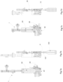
- the filling device 1 in fact comprises, in sequence, from the top down, a dosing device 50, a diverting valve 60 and the nozzle 10.
- a corresponding amount of filling product is introduced into the dosing device 50, for example, by a suctioning system due to the motion of an inner plunger 52 to a filling chamber 51 of the dosing device.
- This working phase is referred to herein below as the suctioning phase.
- the dosing device 50 is filled during the suctioning phase with a quantity of product that corresponds to the one that has to be inserted into the container 100 to be filled.
- Said nozzle 10 comprises an outlet mouth 11 from which the product exits to be introduced into the container 100
- the outlet port 11 is located near the container 100 above the inlet 101 of the container 100, as highlighted in Figs. 7b, 7d and 9b, 9d .
- the outlet port 11 can be placed inside the container 100, in particular in the proximity of the bottom of the container 100.
- the diverting valve 60 is generally a three-way valve, preferably of the rotary type.
- Said diverting valve 60 preferably comprises a valve body 65 that is movable and placed inside a seat 66 of the diverting valve 60.
- valve body 65 between a suctioning position I and a filling position II allows to respectively perform the suctioning phase and the filling phase of the of the dosing device 50.
- valve body 65 is positioned as to put in fluid comunication a filling chamber 51 of the dosing device 50 with the tanks 201 containing the product; the plunger 52 of the dosing device rises to create the suction effect that leads to the filling of the chamber 51 with the product.
- valve body 65 In said position of the valve body 65, referred to as the suctioning position I, the valve body 65 does not allow the passage of product from the filling chamber 51 of the dosing device 50 to the nozzle 10.
- valve body 65 is conversely positioned as to put in fluid comunication the filling chamber 51 of the dosing device 50 with the nozzle 10; the plunger 52 of the dosing device lowers to make the product exit from the filling chamber 51.
- valve body 65 In said position of the valve body 65, referred to as the filling position II, the valve body 65 prevents the passage of the product between the filling chamber 51 of the dosing device 50 and the tanks 201 containing the product.
- the diverting valve 60 comprises a driving member 61 rotatable according to a first rotational axis X orthogonal to a vertical direction Z.
- the achievement of the two suctioning I and filling II positions of the diverting valve 60 is generally carried out by said driving member 61, which preferably rotates integral with the valve body 65.
- Said drive member 61 preferably is rotated by engaging/disengaging with an engaging profile 62 of the rotary filling machine 200.
- said engaging profile 62 extends along a stretch of circumference of the stroke along which said devices 1 move during the rotation of the rotary filling machine 200.
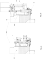
- the filling device 1 provides, between the diverting valve 60 and the nozzle 10, for a discharge manifold 40 onto which a shutter member 30 acts.
- Said shutter member 30 allows and/or prevents the passage of the product 200 to the nozzle 10.
- said shutter member 30 is movable at least between a first position A and a second position C.
- the first position A is one of the possible positions referred to as opening positions, in which the shutter member 30 allows the passage of the product to the nozzle 10.
- the second position C can be one of the possible positions referred to as opening positions, in which the shutter member 30 allows the passage of the product to the nozzle 10, for example in a partialised manner.
- the second position C is one of the possible positions referred to as closure positions, in which the shutter member 30 prevents said passage.
- the shutter member 30 operates in a related way to the diverting valve 60.
- the shutter member 30 when the diverting valve 60 is in the filling phase, the shutter member 30 is in the first position A, preferably the open position A, i.e. it allows for the passage of the product from the discharge manifold 40 to the nozzle 10.
- the shutter member 30 when the diverting valve 60 is in the suctioning phase, the shutter member 30 is at the second position C, preferably the closed position C, i.e. it blocks the passage of the product from the discharge manifold 40 to the nozzle 10.
- a possible embodiment can provide that, when the diverting valve 60 is in the suctioning phase, the shutter member 30 remains in the first opening position A as it was in the filling phase.
- the filling chamber 51 of the dosing device 50, the dosing valve 60 and the nozzle 10 are in fluid comunication.
- the discharge manifold 40 is preferably located under the diverting valve 60.
- valve body 65 comprises a transfer duct 64, which, in the filling position II, arranges as to put the filling chamber 51 of the dosing device 50 in fluid comunication with discharge manifold 40.
- said discharge manifold 40 comprises an intermediate zone 43, which extends preferably foral between the dosing valve 60 and the nozzle 10.
- Said discharge manifold 40 can additionally comprise an inlet channel 41 and preferably an output channel 42.
- the inlet channel 41 extends from the intermediate zone 43 towards the valve body 65.
- the output channel 42 extends from the intermediate zone 43 towards the nozzle 10.
- the transfer duct 64 is positioned so as to put the filling chamber 51 of the dosing device 50 in fluid comunication with the discharge manifold 40.
- Said transfer duct 64 is preferably arranged in the vertical direction Z when the valve body 65 in the filling position II.
- the transfer duct 64 comprises an exit 64' which is opposed to an input section 41' of the inlet channel 41 of the discharge manifold 40.
- the output channel 42 extends from the intermediate zone 43, preferably upwardly, to the point where an output section 42' thereof intercepts a discharge duct 12 in which the shutter member 30 operates.
- the shutter member 30 operates to allow or prevent the fluid comunication between the discharge manifold 40 and the nozzle 10.
- Said discharge duct 12 can extend above the nozzle 10 and preferably coaxial with a through hole 10' of the nozzle 10.
- the shutter member 30 comprises a plug 31 having a preferably cylindric shape.
- Said plug 31 is preferably capable to slide at least inside the discharge duct 12.
- Said discharge duct 12 is also configured to drive the plug 31 during its translation between the open position A and the closed position C.
- the shutter member 30 is preferably located side by side to the dosing device 50.
- the plug 31 and discharge duct 12 are located side by side to the diverting valve 60, in particular to the opposite side relative to the drive member 61.
- FIG. 5a, 5b an embodiment is represented, in which the shutter member 30, and in particular the plug 31 and discharge duct 12, are not located on the rotation axes X, but on an axis incident thereto to free a communication space between the diverting valve 60 and the tanks 201.
- Aim of said shutter member 30 is to prevent the passage of the product from the discharge manifold 40 to the nozzle 10, for example, according to two possible embodiments.
- the shutter member 30, and in particular the plug 31 reaches a different closed position C, in which it prevents the passage of the product from the discharge manifold 40 to the nozzle 10.
- the shutter member 30 when it is reaching the closed position C, brings the plug 31 in front of the output section 42' blocking the flow from the output channel 42 of the discharge manifold 40.
- the shutter member 30 blocks the output section 42' via a translation of the plug 31, in the vertical direction inside the discharge duct 12.
- the plug 31 of the shutter member 30 flows into the discharge duct 12 and proceeds inside the nozzle 10 to the outlet port 11 thereof.
- the shutter member 30 is said to be is a cleaning member that pushes all the product to exit the outlet port 11 of the nozzle 10.
- the closed position C of the shutter member 30 in such a case coincides with the reaching of the outlet port 11 by the plug 31.
- Said first embodiment is preferably used when the filling product is more viscous than water.
- This operation that carries out a cleaning inside the discharge duct 12 continuing inside the nozzle 10 until the outlet port 11, ensures a complete outflow of the product, that wouldn't otherwise be ensured in conjunction with a product more viscous than water.
- the plug 31 of the shutter member 30 flows inside the discharge duct 12 and stops at an input mouth 13 of the nozzle 10 without sliding thereinto.
- the plug 31 of the shutter member 30 engages on the input port 13 of the nozzle 10 preferably via a sealing member.
- the closed position C of the shutter member 30 in such a case coincides with the reaching of the input port 13 by the plug 31.
- Said second embodiment is preferably used when the filling product is liquid and with a viscosity similar to water.
- This operation by making a seal on input to the nozzle 10 blocks the product and avoids drippings and outflows due to liquid products, which increase as the wear increases in the traditional systems, and can be assessed, with the first embodiment in conjunction with a liquid product.
- the presence of the discharge manifold 40 and of the respective shutter member 30 permits to optimize the filling.
- the product follows a fized path from the diverting valve 60, while in the exit phase it follows another path, which is defined by the discharge manifold duct 40.
- the configuration of the discharge manifold 40 in which the intermediate zone 43 is located below the input section 41' and the input section 42' allows an operation of a syphon type.
- the output section 42' is located also above the input section 41'.
- any formed air bubbles remain trapped in said discharge manifold 40, and in particular the elevated position of the input section 42' makes it so that the bubble, if any, remains confined in the proximity of this are.
- a filling device 1 is achieved, which allows having a better filling precision compared to a device in which only the tap 60 allows/prevents the passage of product.
- the so-shaped nozzle 10 also helps reducing possible leakages from the tap 60, intercepting and blocking them it goes into a fully closed position C.
- the shutter member 30 allows to achieve a precise and istantaneuos closure with the elimination of the dripping and consequently the dripping times.
- the discharge manifold 40 can comprise openable inspection means 45 for the control and cleaning.
- Said inspection means 45 are preferably located under the seat 66, preferably on the side of the drive member 61.
- said inspection means 45 comprise a port 46 hinged to rotate according to a vertical axis for its opening/closure.
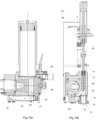
- the device preferably 1 comprises handling means 35 of said shutter member 30.
- said handling means 35 are configured to bring the plug 31 to the closed position C.
- said handling means 35 are configured to make it so that the plug 31 takes the closed position C when the rotary filling machine 200, on which the device 1 is installed, is in the stop phase.
- said closed position C is reached independently of the working phase in progress at the time when the machine 200 has stopped.
- the stop phase can occur due to a emergency stop, or a machine downtime related to stops of other machines of the plant, or in any situations where the machine 200 passes from the operational phase to the not-operational of stop phase.
- a first variation of the invention provides that said handling means 35 intervene only in the stop phase.
- said handling means 35 can be operative on all stations of the machine 200, or only on the stations in which the filling is performed and therefore on the ones where the filling is in progress at the time of stop.
- said handling means 35 can be installed on the rotary filling machine 200 so as to cooperate with the device 1 at the stations configurated for the filling.
- said handling means 35 can be provided only at the filling stations.
- This first variation provides for making the handling means 35 work to bring the plug to the closed position C only in the stop phase of the machine 200.
- said first variation in particular provides for the presence on the rotary filling machine 200 of a mechanic cam, not represented in the Figure, which cooperates with an engagement member of the shutter member 30 to bring it from the closed position C to the open position A, and vice versa.
- the shutter member 30 is driven by the mechanic cam of the rotary filling machine 200, and in particular at each relative position between the cam and filling device 1 a precise working phase and a precise position of the shutter member 30 correspond.
- the handling means 35 intervene in place of the mechanic cam, only in the machine 200 stop phase to prevent the exit of the product, preferably at the filling stations.
- a second, more flexible, variation represented in the Figure, provides that said handling means 35 may be associated with each filling device 1.
- Said solution does not provide for the presence on the rotary filling machine 200 of a mechanic cam, which cooperates with an engagement member of the shutter member 30 for the operation during the entire working cycle.
- the handling means 35 move the shutter member 30 during the entire working cycle.
- said handling means 35 are configured to be able to move the shutter member 30, independently of the operational position at which the device 1 is lcoated, during the working cycle of the machine 200 and therefore independently of the device 1 being in a filling or suctioning phase.
- each filling device 1 preferably comprises handling means 35 integrated to it.
- Said handling means 35 are internally installed on the filling device 1.
- the handling of the shutter member 30 always occurs via the handling means 35, both during the working cycle and during the possible stop phases of the machine 200.
- each shutter member 30 can work with a law of motion different from product 200 to product 200.
- the product 200 it is also possible to decide to perform partial closures or openings, multiple cycles of closure, or not to perform the closure of the shutter member 30.
- said handling means 35 are configured to translate according to a vertical direction Z said shutter member 30 from the first position A to the second position C, and vice versa.
- said handling means 35 are placed located and coaxial with the shutter member 30, in particular the plug 31.
- Said handling means 35 comprise a piston 36, preferably of the pneumatic type.
- the shutter device 30 and the handling means 35 are positioned side by side to the dosing device 50.
- the handling means 35 are positioned side by side to the filling chamber 51.
- An embodiment represented in the figures provides for the shutter member 30 to be in the closed position C when the piston 36 is in the extended, i.e., lowered, configuration.
- the shutter member 30 is in the open position A when the piston 36 is in the retracted, i.e., raised, configuration.
- the shutter member 30 allows for an adjustable closure according to a law of motion suitable to the fluid being processed.
- drive and management members are preferably present, that allow to vary the management of the handling means 35 to adapt the operation of the shutter member 30 to particular working conditions.
- the device 1 can be used in a very flexible manner, with products having different consistency, to achieve optimal closure and/or opening for a determinated product.
- the shutter member 30 carries out a closing cycle which involves, for example, multiple cycles, a double cycle: closing, opening. and closing again.
- This operation is particularly effective to manage products 200 that make a thread or that are sticking.
- said handling means 35 allow moving the shutter member 30 independently of the operational position of the dosing device 50 and/or the diverting valve 60.
- the shutter element 30 does not carry out the closing cycle, such as for example with products such as mayonnaise.
- the shutter member 30 remains at the first filling position A.
- a preferred enbodiment provides that that components described above require setting and disassembly that can be carried out completely without tools and therefore in a simple and quick manner.
Landscapes
- Filling Of Jars Or Cans And Processes For Cleaning And Sealing Jars (AREA)
Applications Claiming Priority (1)
| Application Number | Priority Date | Filing Date | Title |
|---|---|---|---|
| IT102023000011145A IT202300011145A1 (it) | 2023-05-31 | 2023-05-31 | Riempitrice rotativa con dispositivo per il riempimento di contenitori migliorato |
Publications (1)
| Publication Number | Publication Date |
|---|---|
| EP4470965A1 true EP4470965A1 (fr) | 2024-12-04 |
Family
ID=88098373
Family Applications (1)
| Application Number | Title | Priority Date | Filing Date |
|---|---|---|---|
| EP24179383.5A Pending EP4470965A1 (fr) | 2023-05-31 | 2024-05-31 | Machine de remplissage rotative |
Country Status (2)
| Country | Link |
|---|---|
| EP (1) | EP4470965A1 (fr) |
| IT (1) | IT202300011145A1 (fr) |
Citations (3)
| Publication number | Priority date | Publication date | Assignee | Title |
|---|---|---|---|---|
| GB2214612A (en) * | 1988-01-20 | 1989-09-06 | Ocme Spa | Drip-preventing nozzle for a metering unit for the packaging of a product with a fluid bahaviour |
| US20100300580A1 (en) * | 2007-12-17 | 2010-12-02 | Sidel Participations | Machine for filling vessels with two products |
| EP3064469B1 (fr) * | 2015-03-05 | 2018-01-24 | Krones Ag | Dispositif de remplissage d'un recipient |
-
2023
- 2023-05-31 IT IT102023000011145A patent/IT202300011145A1/it unknown
-
2024
- 2024-05-31 EP EP24179383.5A patent/EP4470965A1/fr active Pending
Patent Citations (3)
| Publication number | Priority date | Publication date | Assignee | Title |
|---|---|---|---|---|
| GB2214612A (en) * | 1988-01-20 | 1989-09-06 | Ocme Spa | Drip-preventing nozzle for a metering unit for the packaging of a product with a fluid bahaviour |
| US20100300580A1 (en) * | 2007-12-17 | 2010-12-02 | Sidel Participations | Machine for filling vessels with two products |
| EP3064469B1 (fr) * | 2015-03-05 | 2018-01-24 | Krones Ag | Dispositif de remplissage d'un recipient |
Also Published As
| Publication number | Publication date |
|---|---|
| IT202300011145A1 (it) | 2024-12-01 |
Similar Documents
| Publication | Publication Date | Title |
|---|---|---|
| US3289712A (en) | Receptacle filling machines | |
| US5137187A (en) | Anti-spray fluid dispensing nozzle | |
| EP2454164B1 (fr) | Robinet | |
| US9720425B2 (en) | Low splash fluid shutoff valve assembly | |
| US5551491A (en) | Automatic carousel machine for the metered feeding and packaging of fluid products | |
| US3799220A (en) | Apparatus for aseptic packing or conditioning of products, notably food products | |
| US7011117B1 (en) | Filling valve | |
| US3349973A (en) | Receptacle filling machines | |
| EP3581542B1 (fr) | Soupape de remplissage et machine de remplissage pour remplir des récipients | |
| EP4470965A1 (fr) | Machine de remplissage rotative | |
| EP0780338B1 (fr) | Réservoir de rinçage pour le cycle de nettoyage dans une machine de remplissage | |
| US4593730A (en) | Liquid dispensing apparatus | |
| US4541463A (en) | Filler on packing machines | |
| US3459340A (en) | Receptacle filling machines | |
| US3351250A (en) | Valve for viscous fluids | |
| US3358719A (en) | Drip collector for receptacle filling machines | |
| PL206202B1 (pl) | Urządzenie dozujące do produktów płynnych | |
| EP1279339B1 (fr) | Dispositif pour la production des boissons glacées comprenant un dispositif de distribution amelioré | |
| EP4321473A1 (fr) | Dispositif de remplissage de récipients | |
| US6041576A (en) | Fill system for particulates | |
| US1837592A (en) | Dispensing machine | |
| US4394876A (en) | Container filling machine | |
| CN115057018B (zh) | 一种清爽沐浴露制备工艺 | |
| EP3980366B1 (fr) | Soupape de remplissage permettant de remplir des récipients avec un produit versable | |
| DE2231082A1 (de) | Vorrichtung zum dosierten abfuellen von sterilen fluessigkeiten wie milch und aehnliche fuellgueter |
Legal Events
| Date | Code | Title | Description |
|---|---|---|---|
| PUAI | Public reference made under article 153(3) epc to a published international application that has entered the european phase |
Free format text: ORIGINAL CODE: 0009012 |
|
| STAA | Information on the status of an ep patent application or granted ep patent |
Free format text: STATUS: THE APPLICATION HAS BEEN PUBLISHED |
|
| AK | Designated contracting states |
Kind code of ref document: A1 Designated state(s): AL AT BE BG CH CY CZ DE DK EE ES FI FR GB GR HR HU IE IS IT LI LT LU LV MC ME MK MT NL NO PL PT RO RS SE SI SK SM TR |
|
| STAA | Information on the status of an ep patent application or granted ep patent |
Free format text: STATUS: REQUEST FOR EXAMINATION WAS MADE |
|
| 17P | Request for examination filed |
Effective date: 20250603 |
|
| P01 | Opt-out of the competence of the unified patent court (upc) registered |
Free format text: CASE NUMBER: APP_26743/2025 Effective date: 20250605 |