EP4480642A1 - Verbesserter industrieroboter vom delta-typ mit einem verbindungselement - Google Patents
Verbesserter industrieroboter vom delta-typ mit einem verbindungselement Download PDFInfo
- Publication number
- EP4480642A1 EP4480642A1 EP24182629.6A EP24182629A EP4480642A1 EP 4480642 A1 EP4480642 A1 EP 4480642A1 EP 24182629 A EP24182629 A EP 24182629A EP 4480642 A1 EP4480642 A1 EP 4480642A1
- Authority
- EP
- European Patent Office
- Prior art keywords
- wrist
- arm
- connection line
- industrial robot
- primary
- Prior art date
- Legal status (The legal status is an assumption and is not a legal conclusion. Google has not performed a legal analysis and makes no representation as to the accuracy of the status listed.)
- Pending
Links
Images


Classifications
-
- B—PERFORMING OPERATIONS; TRANSPORTING
- B25—HAND TOOLS; PORTABLE POWER-DRIVEN TOOLS; MANIPULATORS
- B25J—MANIPULATORS; CHAMBERS PROVIDED WITH MANIPULATION DEVICES
- B25J9/00—Program-controlled manipulators
- B25J9/003—Program-controlled manipulators having parallel kinematics
- B25J9/0045—Program-controlled manipulators having parallel kinematics with kinematics chains having a rotary joint at the base
- B25J9/0051—Program-controlled manipulators having parallel kinematics with kinematics chains having a rotary joint at the base with kinematics chains of the type rotary-universal-universal or rotary-spherical-spherical, e.g. Delta type manipulators
-
- B—PERFORMING OPERATIONS; TRANSPORTING
- B25—HAND TOOLS; PORTABLE POWER-DRIVEN TOOLS; MANIPULATORS
- B25J—MANIPULATORS; CHAMBERS PROVIDED WITH MANIPULATION DEVICES
- B25J19/00—Accessories fitted to manipulators, e.g. for monitoring, for viewing; Safety devices combined with or specially adapted for use in connection with manipulators
- B25J19/0025—Means for supplying energy to the end effector
Definitions
- the present invention concerns the technical field of industrial robots for moving and positioning objects in space.
- the present invention refers to a robot with Delta geometry (parallel kinematic mechanism with two or more degrees of freedom) for the operations of gripping, manipulation, positioning and assembling small to medium-sized and lightweight objects, which finds application in a wide variety of manufacturing sectors such as food, cosmetic, pharmaceutical, small metal parts, palletising, packaging sector and the like.
- Delta geometry parallel kinematic mechanism with two or more degrees of freedom
- the present invention also finds application in the field of 3D printers that use a Delta robot-like mechanics.
- Industrial robots such as for example the Delta robot, as the one described in US patent 4,976,582 , are known in the industrial sector for the gripping, manipulating and positioning of objects in space.
- This robot comprises a fixed base on which two or more motors are mounted that directly or indirectly drive the respective articulated arms connected to a movable platform, commonly called a "wrist", on which one or more auxiliary devices can be mounted, such as for example gripping elements, extruders, sensors, etc.
- a movable platform commonly called a "wrist”
- auxiliary devices such as for example gripping elements, extruders, sensors, etc.
- the Delta robot can have two or more degrees of freedom: two or more translations and, possibly, one or more rotations. In some cases, one or more rotations are performed by arms extending from the fixed base to the centre of the movable platform giving the end device one or more rotational degrees of freedom. In other cases, the rotational degrees of freedom available at the end of the robot ("wrist") are performed through motors or servomotors or pneumatic systems or oleodynamic systems installed at the end of the robot itself.
- Each of the articulated arms consists of a primary arm, one or more secondary arms and one or more joints.
- the primary arm has a longitudinal development and comprises two longitudinally opposite ends, of which the first end is directly or indirectly connected to a motor and the opposite end is directly or indirectly connected to one or more secondary arms.
- the relative movement between the primary arm and the secondary arm(s) is obtained through one or more joints of various types (for example, rotary, prismatic, spherical, sliding, or similar).
- Each secondary arm has a longitudinal development, in which the first end is connected to the primary arm and the second end is in turn connected to the "wrist".
- the relative movement between wrist and secondary arm is obtained through one or more joints of various types (for example, rotary, prismatic, spherical, sliding or similar).
- One or more auxiliary devices for example mechanical grippers, pneumatic grippers, suction cups, extruders, sensors, Venturi tubes, solenoid valves, or the like, depending on the application of the Delta robot required, can be removably mounted on the "wrist".
- the auxiliary device arranged on the "wrist" may require one or more connections for the purpose of its operation, for example pneumatic, hydraulic, oleodynamic, electrical, optical and/or solids conveying and/or dust conveying type connections (for example, the extruders of 3D printers need a connection that carries the material to be extruded).
- the auxiliary device is connected to the fixed base of the robot through one or more connection lines.
- the connection lines are used for conveying gases and/or vapours (e.g. compressed air, air being sucked to generate the vacuum etc%), liquid (e.g. compressed oil for oleodynamic grippers), solids and/or dusts (e.g. material for the extruder, abrasive dusts for a cutting head), electric current (e.g. analogue signal, digital signal, power supply current) and/or optical signal (e.g. optical fibre, laser etc).
- gases and/or vapours e.g. compressed air, air being sucked to generate
- connection lines also called utility lines, for example consisting of electrical cables, air connections, hydraulic pipes, etc... that run from the fixed base up to the device.
- a drawback of Delta robots of known type is due to the fact that during operation they move with accelerations that even exceed 10 g of acceleration, leading to strong vibrations that can cause failures or breakages in the connection lines mounted externally to the articulated arms.
- a further drawback of Delta-type robots is due to the relatively high range of movement and/or to the type of movement itself in three-dimensional space, which can cause failures or breakages in the connection lines mounted externally to the articulated arms.
- cables and/or pipes constrained externally to the arms may be twisted-bent due to the relative movement of the arms themselves.
- connection lines run externally
- dirt can accumulate in the spaces between the connection lines and the primary and/or secondary arms to which they are constrained, proving difficult to be reached for cleaning.
- connection line in the event of failures or breakages of the connection line, the latter must be replaced for the entire section running from the fixed base up to reaching the wrist on which the auxiliary device is mounted. This operation of replacing or repairing the connection line therefore requires a high machine downtime with consequent high maintenance costs.
- auxiliary devices mounted in positions other than the "wrist" of the robot, such as for example motors positioned along one or more articulated arms.
- a first object of the present invention is to realize an industrial robot with parallel kinematics of simple construction and maintenance.
- a further object of the present invention is to provide an industrial robot that allows to quickly replace possible sections of the connection line in case of breakages, leaks or failures.
- Another object of the present invention is to provide an industrial robot with parallel kinematics, which makes possible a reliable cleaning of all the components, decreasing the possibility of damaging the connection lines.
- a further object of the present invention is to eliminate the drawbacks of the prior art, by providing an industrial robot that is practical, versatile, efficient and adapted to ensure good freedom of movement.
- Yet another object of the present invention is to provide an industrial robot that is suitable for use in the food sector.
- a first object of the present invention consists in an industrial robot comprising:
- the Delta-type industrial robot according to the present invention enables increased reliability and maintenance.
- connection line allows to speed up the operations of replacement of portions of the connection line in the event of breakage, leaks or failures, allowing to replace only the portions of the connection line that are mostly exposed to potential breakages and failures.
- the Delta-type industrial robot according to the present invention also allows easy cleaning of the primary and secondary arms, decreasing the risk of any breakages or failures of the connection lines.
- the Delta-type industrial robot according to the present invention allows to decrease the possibility of failures or breakages of the various connection lines due to high vibrations and/or movement to which the articulated arms and/or wrist are subject.
- the Delta-type industrial robot according to the present invention allows to have one or more connection lines that do not hinder the movements of the industrial robot during operation.
- the Delta-type industrial robot according to the present invention can be configured by choosing how many and what types of connection lines are installed.
- the Delta-type industrial robot according to the present invention allows to change the configuration and arrangement of the connection lines mounted even to robots already installed and even after a period of operation.
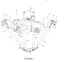
- the articulated system for moving the wrist 3 comprises three primary arms or cranks 5a, 5b, 5c rotatably driven by respective motors and connected, by means of pairs of secondary arms or connecting rods 6a, 6b, 6c to said wrist 3, the ends of said pairs of secondary arms 6a, 6b, 6c being connected by means of joints to the primary arms 5a, 5b, 5c and to the wrist 3.
- At least one of the three primary arms 5a, 5b, 5c has a first cavity and/or at least one secondary arm of one of said pairs of secondary arms 6a, 6b, 6c has a second cavity.
- the robot 1 comprises at least one connection line 21, 28 which is pneumatic and/or hydraulic and/or oleodynamic and/or electric and/or optical and/or for solids conveying and/or for dust conveying for the one or more said auxiliary devices.
- the connection line 21, 28 is partially housed within the primary arm 5a, 5b, 5c, within said first cavity, and/or partially housed within at least one secondary arm 6a, 6b, 6c, in connection with the primary arm comprising the first cavity, in said second cavity.
- the first cavity and the second cavity are each a continuous cavity extending longitudinally between the two longitudinal ends of the primary arm 5a, 5b, 5c and of the at least one secondary arm of one of said pairs of secondary arms 6a, 6b, 6c.
- the primary arm 5a, 5b, 5c and the at least one secondary arm of one of said pairs of secondary arms 6a, 6b, 6c has a tubular shape, hollow therein, configured to house therein at least a portion of the connection line 21, 28.
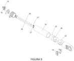
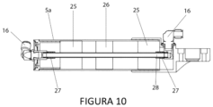
- the primary arm 5a, 5b, 5c and the at least one secondary arm of one of said pairs of secondary arms 6a, 6b, 6c that are internally hollow, have at the ends of the hollow tubular shape at least one connector 16, 19 configured to let the connection line 21, 28 pass without interruptions.
- connection line which is pneumatic and/or hydraulic and/or oleodynamic and/or electrical and/or optical and/or for solids conveying and/or for dust conveying 21, 28 is housed within the hollow tubular shape fixed with a support element interposed between the connection line 21, 28 and the internal walls of the tubular shape.
- the support element develops longitudinally, along an axis substantially parallel to the longitudinal axis of the primary arm and of the secondary arm, and has a diameter substantially equal to the inner diameter of the primary arm and/or of the hollow secondary arm.
- the connection line 21, 28 is inserted inside the support element, along its longitudinal axis, in a substantially central area.
- the support element consists of a low-density material in a central area thereof and of a high-density material at the ends.
- the density of the support material may vary depending on the diameters and weights of the connection line 21, 28.
- the support element may not completely fill the cavity of the arms 5a, 5b, 5c, 6a, 6b, 6c and be distributed longitudinally so as to achieve the best compromise between the overall weight of the arms 5a, 5b, 5c, 6a, 6b, 6c and the stability of the connection line 21, 28.
- the presence of the support element makes it possible to hold the connection line steady and to preserve it from the strong vibrations that are generated during the operation of the industrial robot.
- the low-density central area of the support element enables the support of the connection line and at the same time it serves to keep the support itself light.
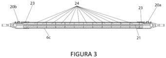
- the support element consists of a plurality of adj acent rings 23, 24, 25, 26 in polyurethane foam.
- the support element comprises a longitudinal opening that runs through it entirely along its length, configured to insert and accommodate the connection line 21, 28 in a central position, inside it.
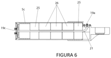
- the primary arm 5a, 5b, 5c and/or inside the at least one secondary arm of one of said pairs of secondary arms 6a, 6b, 6c, comprising said hollow tubular shape there are one or more support elements as described above preferably arranged in correspondence with the inlet/outlet connectors 16, 19a, 19b of the connection line 21, 28, placed at the ends of the primary arm and/or of the secondary arm.
- connection lines 21, 28 are housed, each of which can continue towards the wrist 3 and is housed within each secondary arm of the pair of secondary arms 6a, 6b, 6c.
- the primary arms 5a, 5b, 5c and the pairs of secondary arms 6a, 6b, 6c may have a cylindrical or polygonal section.
- the primary arms 5a, 5b, 5c and the pairs of secondary arms 6a, 6b, 6c are made of metallic material or of carbon or of plastic material or a combination thereof.
- connection lines 21 are made of tubes of aluminium or of carbon or of plastic material, either rigid or flexible.
- the primary arm 5a, 5b, 5c and/or the at least one secondary arm of one of the pairs of secondary arms 6a, 6b, 6c that are internally hollow comprises a valve element configured to selectively vent outwards any air overpressure present inside.
- the pneumatic connection lines may be subject to air leaks inside the primary arm and/or the secondary arm in which they are housed. Such leaks may result in breakages and/or explosions of the primary arm or secondary arm itself.
- valves are a cap, held steady by a tie, so that in the event of any overpressures being vented, it prevents the little cap from ending up in the products processed by the industrial robot.
- such caps may possibly be rearranged in their seat from the outside and/or may not be pushed too far inside so as to invalidate their operation.
- the diameter of the valve element is equal to the diameter of the air conducting tube 28.
- the first connecting element 7, 8, 9, 10 comprises, in at least one of its two opposite ends, a connector 16, 19 configured to removably connect to a corresponding connector 16, 19 present, respectively, in an end of the primary arm 5a, 5b, 5c and/or of the at least one secondary arm of one of said pairs of secondary arms 6a, 6b, 6c comprising the hollow tubular shape.
- the industrial robot 1 comprises a second connecting element or link 11, 12, 13, 14 configured to continuously connect the connection line 21, 28 between the fixed base 2 with the interior of the first cavity, included within the primary arm 5a, 5b, 5c.
- the industrial robot 1 advantageously comprises a third connecting element or link (not shown in the attached figures) configured to continuously connect the connection line 21, 28 between said second cavity included within said at least one secondary arm of one of the pair of secondary arms 6a, 6b, 6c and the one or more auxiliary devices mounted on the wrist 3.
- a third connecting element or link (not shown in the attached figures) configured to continuously connect the connection line 21, 28 between said second cavity included within said at least one secondary arm of one of the pair of secondary arms 6a, 6b, 6c and the one or more auxiliary devices mounted on the wrist 3.
- connection line is subdivided into three connecting elements and two portions housed firmly within the primary arm 5a, 5b, 5c and the secondary arm 6a, 6b, 6c.
- connection line 21, 28 is for exemplary purpose and is not binding, as it can be used even only partially.
- connection elements 13, 14 and of the portions housed within the primary arm 5a, 5b, 5c it is possible to take advantage of the connecting elements 13, 14 and of the portions housed within the primary arm 5a, 5b, 5c, to connect to auxiliary devices placed on a secondary arm 6a, 6b, 6c, without taking advantage of the other elements that make up the connection line.
- Each connecting element 7, 8, 9, 10, 11, 12 is external to the various elements that make up the industrial robot 1 (i.e. fixed base 2, primary arm 5a, 5b, 5c, secondary arm 6a, 6b, 6c and wrist 3) and can be quickly replaced in the event of breakage and/or failure.
- each connecting element is placed in correspondence with the connection joints.
- connection lines 21, 28 are housed within the primary arm 5a, 5b, 5c, each of which then continues towards the cavity of a corresponding secondary arm 6a, 6b, 6c to which it is continuously connected by the first connecting element 7, 8, 9, 10.
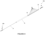
- a first embodiment of the present invention relating to the electrical connection line 21, is shown in figures 3 to 6 .
- the support element houses therein the electrical cable and the various connectors 19a, 19b are configured to continuously connect the electrical signal between the various elements that make up the robot 1 (fixed base 2, primary arm 5a, 5b, 5c, secondary arm 6a, 6b, 6c and wrist 3).
- the various connectors 19a, 19b are configured to continuously connect the electrical signal between the various elements that make up the robot 1 (fixed base 2, primary arm 5a, 5b, 5c, secondary arm 6a, 6b, 6c and wrist 3).
- the electrical cable 21 will be connected to two other respective electrical connectors 21.
- a third external electrical connection portion will connect each electrical connection line between the lower electrical connector and the one or more auxiliary devices mounted on the wrist.
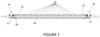
- a second embodiment of the present invention relating to the pneumatic connection line 28, is shown in figures 7 to 11 .
- the support element houses therein a tubular element 28 of suitable diameter for compressed air or for creating the vacuum.
- the connectors 16 are configured to continuously connect air or vacuum between the various elements that make up the robot 1 (fixed base 2, primary arm 5a, 5b, 5c, secondary arm 6a, 6b, 6c and wrist 3).
- the tubular element 28 will be connected to two other respective pneumatic connectors 28.
- An external connection portion 7, 8 for each of the two tubular elements 28 that are housed within the primary arm will continuously connect the pneumatic flow (i.e. compressed air or vacuum) between the second end of the primary arm and the first end of a secondary arm.
- the two tubular elements 28 present within the primary arm are pneumatically connected respectively to each secondary arm of the pair of secondary arms to which the primary arm is connected with a joint.
- each tubular element 28 running internally to each secondary arm will terminate near the second end of each secondary arm, in two pneumatic connectors (one for each secondary arm).
- a third external electrical connection portion will connect each pneumatic connection line between the pneumatic connector on the lower end of the connecting rod and the one or more auxiliary devices mounted on the wrist.
- connection line is a pneumatic line 28
- the tubular elements 28 for the passage of air or vacuum have the same diameter in all the various portions present from the fixed base 2 up to the wrist 3.
- the primary arm 5a, 5b, 5c may have an outer diameter from 10 to 120 mm and an inner diameter from 5 to 118 mm.
- the secondary arm 6a, 6b, 6c may have an outer diameter from 4 to 60 mm and an inner diameter from 1 to 58 mm.
- the tube 28 may have an outer diameter from 3 to 50 mm and an inner diameter from 2 to 48 mm.
- connection line 21, 28 is inserted within the primary arm and the secondary arm forming "a curl". In this way, any twists of the arms of the robot 1 are advantageously transformed into a bending.
- Non-limiting examples of auxiliary devices that are removably mountable on the "wrist" 3 of the robot 1 comprise: a mechanical gripper, a suction cup, multiples of suction cups, an extruder (3D printer), optical devices for reflection and conduction of light rays, a cutting blade, multiples of cutting blades, a water jet for cutting or engraving operations, a laser head for cutting, engraving ablation, one or a multiplicity of tools for grinding, polishing, cleaning, one or a multiplicity of spindles with mounted a tool for chip removal, a quick change system to hook several tools or bits or tools adapted to perform the process necessary for the user of the robot.
- a mechanical gripper a suction cup, multiples of suction cups, an extruder (3D printer), optical devices for reflection and conduction of light rays, a cutting blade, multiples of cutting blades, a water jet for cutting or engraving operations, a laser head for cutting, engraving ablation, one or a multiplicity of tools for grinding, polishing, cleaning
- auxiliary devices comprise: Venturi tube, solenoid valves, proximity sensors, force sensors, rotary encoders, linear encoders, pneumatic grippers, linear and/or rotary electric actuators, linear and/or rotary pneumatic actuators, linear and/or rotary hydraulic actuators, cams, linear and/or rotary electromagnetic actuators, grippers, robotic hands.
- connection line portion the presence of the external connection portions allows, at the points more subject to failures or breakages, to be able to quickly replace the damaged connection line portion.
Landscapes
- Engineering & Computer Science (AREA)
- Robotics (AREA)
- Mechanical Engineering (AREA)
- Manipulator (AREA)
Applications Claiming Priority (1)
| Application Number | Priority Date | Filing Date | Title |
|---|---|---|---|
| IT102023000012579A IT202300012579A1 (it) | 2023-06-19 | 2023-06-19 | Robot industriale di tipo delta perfezionato comprendente un elemento di raccordo |
Publications (1)
| Publication Number | Publication Date |
|---|---|
| EP4480642A1 true EP4480642A1 (de) | 2024-12-25 |
Family
ID=88097859
Family Applications (1)
| Application Number | Title | Priority Date | Filing Date |
|---|---|---|---|
| EP24182629.6A Pending EP4480642A1 (de) | 2023-06-19 | 2024-06-17 | Verbesserter industrieroboter vom delta-typ mit einem verbindungselement |
Country Status (2)
| Country | Link |
|---|---|
| EP (1) | EP4480642A1 (de) |
| IT (1) | IT202300012579A1 (de) |
Citations (4)
| Publication number | Priority date | Publication date | Assignee | Title |
|---|---|---|---|---|
| US4976582A (en) | 1985-12-16 | 1990-12-11 | Sogeva S.A. | Device for the movement and positioning of an element in space |
| EP2835226A1 (de) * | 2013-08-09 | 2015-02-11 | Yamaha Hatsudoki Kabushiki Kaisha | Verdrahtungsstruktur für Roboterarm |
| EP3112093A1 (de) * | 2015-06-30 | 2017-01-04 | Yamaha Hatsudoki Kabushiki Kaisha | Industrieroboter |
| US20190061144A1 (en) * | 2017-08-23 | 2019-02-28 | Fanuc Corporation | Robot and parallel link robot |
-
2023
- 2023-06-19 IT IT102023000012579A patent/IT202300012579A1/it unknown
-
2024
- 2024-06-17 EP EP24182629.6A patent/EP4480642A1/de active Pending
Patent Citations (4)
| Publication number | Priority date | Publication date | Assignee | Title |
|---|---|---|---|---|
| US4976582A (en) | 1985-12-16 | 1990-12-11 | Sogeva S.A. | Device for the movement and positioning of an element in space |
| EP2835226A1 (de) * | 2013-08-09 | 2015-02-11 | Yamaha Hatsudoki Kabushiki Kaisha | Verdrahtungsstruktur für Roboterarm |
| EP3112093A1 (de) * | 2015-06-30 | 2017-01-04 | Yamaha Hatsudoki Kabushiki Kaisha | Industrieroboter |
| US20190061144A1 (en) * | 2017-08-23 | 2019-02-28 | Fanuc Corporation | Robot and parallel link robot |
Also Published As
| Publication number | Publication date |
|---|---|
| IT202300012579A1 (it) | 2024-12-19 |
Similar Documents
| Publication | Publication Date | Title |
|---|---|---|
| JP5560260B2 (ja) | 多関節マニピュレータおよびロボットシステム | |
| US4365928A (en) | Fluid power connector system for manipulator | |
| US9764482B2 (en) | Industrial robot | |
| KR20130129852A (ko) | 핸드 기본 하우징 안에 연장된 드라이브들을 가진 산업용 로봇 | |
| EP2450158A1 (de) | Robotergelenkstruktur und Roboter | |
| US20120118097A1 (en) | Parallel Robot | |
| CN1805831B (zh) | 工业机器人 | |
| JP5139042B2 (ja) | ロボットの手首装置 | |
| JP2001277164A (ja) | 三次元空間内で製品を操作するロボット | |
| EP2401118B1 (de) | Werzeugvorrichtung für roboter | |
| CN108274486B (zh) | 一种模块化的机器人末端执行器及其重构方法与抓取方法 | |
| JP6351244B2 (ja) | アーム機構 | |
| EP4480642A1 (de) | Verbesserter industrieroboter vom delta-typ mit einem verbindungselement | |
| US11351679B2 (en) | Robot arm having at least one deformation element | |
| EP1491299A1 (de) | Robotisches Handgelenk mit mehreren seriell angeordneten und von Kegelzahnrädern angetriebenen Teilen | |
| EP1131190A1 (de) | Robotervorrichtung | |
| US20190152071A1 (en) | Handling system | |
| EP2153946A1 (de) | Arm mit mehreren Gelenken | |
| KR101211658B1 (ko) | 7자유도 로봇의 아암 | |
| EP0108569B1 (de) | Gelenk und Arm für einen Roboter | |
| WO2007010382A2 (en) | Module for the manufacturing of automated moving structure and automated moving modular structure | |
| JP6886562B2 (ja) | 多関節ロボットアーム | |
| KR20230142085A (ko) | 케이블 손상 방지를 위한 중공형 회전축 구조 및 이를 포함하는 다축 로봇 | |
| CN110997254A (zh) | 机器人 | |
| US20230339099A1 (en) | Parallel-kinematic machine with versatile tool orientation |
Legal Events
| Date | Code | Title | Description |
|---|---|---|---|
| PUAI | Public reference made under article 153(3) epc to a published international application that has entered the european phase |
Free format text: ORIGINAL CODE: 0009012 |
|
| STAA | Information on the status of an ep patent application or granted ep patent |
Free format text: STATUS: THE APPLICATION HAS BEEN PUBLISHED |
|
| AK | Designated contracting states |
Kind code of ref document: A1 Designated state(s): AL AT BE BG CH CY CZ DE DK EE ES FI FR GB GR HR HU IE IS IT LI LT LU LV MC ME MK MT NL NO PL PT RO RS SE SI SK SM TR |
|
| STAA | Information on the status of an ep patent application or granted ep patent |
Free format text: STATUS: REQUEST FOR EXAMINATION WAS MADE |
|
| 17P | Request for examination filed |
Effective date: 20250625 |
|
| STAA | Information on the status of an ep patent application or granted ep patent |
Free format text: STATUS: EXAMINATION IS IN PROGRESS |
|
| 17Q | First examination report despatched |
Effective date: 20250807 |